
Related Manuals for ESAB HandyPlasma 35i


Summary of Contents for ESAB HandyPlasma 35i
- Page 1 HandyPlasma 35i HandyPlasma 45i OPERATING MANUAL HandyPlasma 35i 0559160135 0559160145 HandyPlasma 45i 05/2020 - Revision: AA Manual No.: 0-5584...
- Page 2 Be sure this information reaches the operator. You can get extra copies through your supplier. CAUTION These INSTRUCTIONS are for experienced operators. If you are not fully familiar with the principles of operation and safe practices for arc welding and cutting equipment, we urge you to read our booklet, “Precautions and Safe Practices for Arc Welding, Cutting, and Gouging,”...
- Page 3 ASSUREZ-VOUS QUE CE DOCUMENT D’INFORMATION EST DISTRIBUÉ À L’OPÉRATEUR. DES COPIES SUPPLÉMENTAIRES SONT DISPONIBLES CHEZ VOTRE FOURNISSEUR. MISE EN GARDE Les INSTRUCTIONS suivantes sont destinées aux opérateurs qualifiés seulement. Si vous n’avez pas une connaissance approfondie des principes de fonctionnement et des règles de sécurité...
- Page 4 Brand name or trade mark HandyPlasma Manufacturer or his authorized representative established within the EEA Name, address, telephone No: ESAB 2800 Airport Rd. Denton, TX, 76207 Phone: 001 843 669 4411 The following harmonised standard in force within the EEA has been used in the design: IEC/EN 60974-1:2017 / AMD1:2019 Arc Welding Equipment - Part 1: Welding power sources.
-
Page 5: Table Of Contents
While the information contained in this Manual represents the Manufacturer's best judgment, the Manufacturer assumes no liability for its use. Published by: Copyright 2020 by ESAB. All rights reserved. ESAB 2800 Airport Rd. Denton, TX 76208 TABLE OF CONTENTS 1 SAFETY ................. -
Page 6: Safety
1 SAFETY WARNING AVERTISSEMENT 1. Les étincelles de coupage peuvent 1. Cutting sparks can cause explosion or fire. provoquer une explosion ou un 1.1 Do not cut near flammables. incendie. 1.2 Have a fire extinguisher nearby and 1.1 Ne pas couper près des matières ready to use. -
Page 7: Introduction
Means immediate hazards which, if not avoided, will result in immediate, serious personal injury or loss of life. Electronic copies of this manual can be downloaded in Acrobat PDF format by going to the ESAB web site listed below: Enter manual part number. -
Page 8: Handyplasma Features
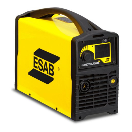
2.2 HandyPlasma features 12 mm max HandyPlasma 35i carbon steel 16 mm max HandyPlasma 45i Front Panel Controls The HandyPlasma equipment provides excellent cutting performance when used with the correct consumables and plasma cutting procedures. The following instructions detail the appropriate safe configuration of the equipment and provide directives to obtain the best efficiency and quality. -
Page 9: Equipment Identification/ User Responsibility
2.3 Equipment Identification/ User responsibility ✅ ✅ ���� ✅ ✅ ���� HandyPlasma 35i HandyPlasma 45i OPERATING MANUAL HandyPlasma 35i 0559160135 HandyPlasma 45i 0559160145 05/2020 - Revision: AA Manual No.: 0-5584 Inspect each item regarding possible damage during shipping. If the damage is evident, contact your distributor and/or carrier before proceeding with the installation. -
Page 10: Technical Data
TABLE 3.1 TECHNICAL DATA INVERTER HANDYPLASMA Equipment development technology Inverter Equipment model HandyPlasma 35i HandyPlasma 45i Efficiency 84% @35A/94V 84% @45A/98V Idle state power consumption 35 W 35 W Network voltage 220~240V - 1Ø... -
Page 11: Generator Recommendations
TABLE 3.2 MODEL GENERATOR RATED OUTPUT 8 kVA (with power factor of 0.8) HandyPlasma 35i 6.4 KW (with power factor of 1.0) 9 kVA (with power factor of 0.8) HandyPlasma 45i 7.2 KW (with power factor of 1.0) -
Page 12: Installation
4 INSTALLATION 4.1 General The equipment must be installed by trained and qualified professionals. WARNING! This product was designed for industrial use. The user is responsible for taking the appropriate measures. 4.2 Environment This equipment was designed for use in environments with higher risk of electric shock. A. -
Page 13: Power Supply Cables
WARNING! All electrical work must be performed by a qualified expert electrician. WARNING! The grounding terminal is connected to the power supply body via the HandyPlasma plug. It must be connected to a grounding point of the workplace electrical installation. Take care not to invert the input cable ground conductor (green/yellow cable) at any of the main switch of circuit breaker phases, because this applies electrical voltage to the body. -
Page 14: Air Connections
4.6 Air connections Air adapter assembly: NOTE! For a secure seal, apply thread sealant to the fitting threads, according to manufacturer’s instructions. Do not use Teflon tape as a thread sealer, as small particles of the tape may break off and block the small air passages in the torch. C) 8 mm Pin B) Clip A) Gas Supply Hose with... - Page 15 Installing Optional Inline Filter An optional inline filter is recommended for improved filtering with compressed air and keeping moisture or debris out of the torch. D) 1/4” NPT port C) Filter B) Clip A) Hose Figure 4.3 - Connecting Inline Filter NOTE! Adjust the gas cylinder pressure between 6 and 8 bar.
-
Page 16: Torch And Lead Connections
4.7 Torch and Lead connections Ground Lead connection Ensure connection to ground terminal with the 25 mm connector. The plasma cutting current flows through the ground terminal. NOTE! It is essential that the plug is inserted and rotated into place securely to obtain a electrical connection. Torch connection To install the HandyPlasma torch. -
Page 17: Operation
The user is responsible for defining the process and respective cutting procedure of the consumables (wire, gas) and for the results of the operation and application. CAUTION! Do not turn the power supply OFF during cutting (with load). 5.2 Control panel Figure 5.1 - HandyPlasma 35i/45i 0-5584... - Page 18 1. Plasma torch adapter The adapter is the connection point for the plasma cutting torch. To remove the plasma cutting torch, rotate sleeve counter-clockwise and pull. Trigger Switch PIP Switch Electrode Figure 5.2 - Plasma torch connection TABLE 5.1 Pinout table SOCKET PIN FUNCTION Torch trigger...
- Page 19 To adjust the cutting current: • Turn clockwise to increase the cutting current; • Turn counter-clockwise to reduce the cutting current. To select an option in the menu displayed: • The options are highlighted in sequence at each turn. • To change the selection.
-
Page 20: Lcd Display Operation
7. Water collector The water collector equipped collects the water in the compressed air. 8. Water release valve Push the water release valve up to release the water collected in the filter bowl. Use the wrench supplied with the system package to release the filter bowl for cleaning or filter replacement. CAUTION! Do not remove bowl under pressure. - Page 21 MENU SCREEN To enter the menu screen. In the menu screen, the user may adjust the trigger mode, cutting mode, and gas purge. To exit the menu screen, select the main screen icon. Cutting mode Cutting mode Main screen icon Gas purge Figure 5.8 - Menu screen 1) TRIGGER MODE SELECTION SCREEN...
- Page 22 In the 2T mode, the torch trigger must remain pressed to activate the cutting output. The 4T mode is used mainly for long cutting operations in order to reduce operator fatigue. 2) CUTTING MODE SELECTION SCREEN To enter the cutting mode selection. When the cutting mode is highlighted.
- Page 23 Note that when the trigger mode is defined as 4T, the grid cutting mode is not available. In the plate cutting mode with the trigger mode 2T selected, the arc stops when the torch is pulled away from the workpiece during the cutting operations. To restart the pilot arc.
- Page 24 The voltage error screen is displayed when the input voltage is very low or when the PFC circuit fails. In this case, it is advisable to contact an ESAB Authorized Service Center to assess the equipment. Figure 5.20 - Voltage error screen...
- Page 25 In case of overheating, DO NOT Figure 5.21 - Overheating error screen TORCH PART SELECTION Inspect the torch regarding appropriate assembly and parts. The torch parts must correspond to the current type of work operation. Only use original ESAB parts. Washer Diffuser Electrode...
- Page 26 GAS SELECTION Ensure that the gas supply meets the listed requirements. Check the connections and open the power supply. OPERATION SEQUENCE → 5. Check the air pressure. To activate the gas purge function. The gas flows and the screen displays the air pressure. Ensure that the pressure is in the correct range of 4.1 bar to 5.5 bar. Note that the equipment has adjusted the gas pressure to 4.6 bar as the standard value.
- Page 27 Starting in the middle of the workpiece may damage the shielding cup or the Standoff Guide and reduce the tip service life. NOTE! For best parts performance and life, always use the correct parts for the type of operation. Please use the Standoff Guide when piercing or drag cutting.
- Page 28 Cut quality NOTE! Cut quality depends heavily on setup and parameters such as torch standoff, alignment with the workpiece, cutting speed, gas pressures, and operator ability. Cut quality requirements may differ depending on application. For instance, nitride build-up and bevel angle may be major factors when the surface will be welded after cutting.
- Page 29 Slag - When dross is present on carbon steel, it is commonly referred to as either “high speed, slow speed, or top dross”. Dross present on top of the plate is normally caused by too great a torch to plate distance. “Top dross”...
-
Page 30: Maintenance
Disconnect all power before performing ANY service. 6.3 Corrective maintenance Use only original ESAB consumables, torch and leads. Using non-original or unapproved parts lead to automatic cancellation of the warranty provided. Replacement torch and leads can be obtained from ESAB authorized services or from the sales branches indicated in the last page herein. -
Page 31: Equipment Preventive Maintenance Plan
6.4 Equipment preventive maintenance plan Maintain more often Warning! if used under severe Disconnect input power before maintaining. conditions Each Use Visual check of torch tip and electrode Weekly Visually inspect the cables and leads. Replace as needed Visually inspect the torch body, washer, diffuser, electrode, cutting nozzle, shield cup, and standoff guide tip. -
Page 32: Plasma Torch
The torch consists of the following consumable parts: Electrode, nozzle, cover, gas diffuser, and Standoff Guide. The HandyPlasma 60A Torch (Part No. 0559337000) is equipped with a 0.8 mm Tip for HandyPlasma 35i, and 0.9mm Cutting Tip for HandyPlasma 45i. -
Page 33: Introduction To Plasma
7.2 Introduction to Plasma 7.2.1. Plasma Gas Flow Plasma is a gas which has been heated to an extremely high temperature and ionized so that it becomes electrically conductive. The plasma arc cutting and gouging processes use this plasma to transfer an electrical arc to the workpiece. -
Page 34: Torch Maintenance
7.3 Torch maintenance Cleaning the Torch Even if precautions are taken to use only clean air with a torch, eventually the inside of the torch becomes coated with residue. This build-up can affect the pilot arc ignition and the overall cut quality of the torch. CAUTION! Disconnect primary power to the system before disassembling the torch or torch leads. -
Page 35: Troubleshooting Guide
If the main complex sub-assemblies are defective, the power supply must be returned to an authorized ESAB service provider for repair. The basic problem solution level can be performed without equipment or special knowledge. -
Page 36: Parts Lists
9 PARTS LISTS Consumables, torches, leads, and accessories are available through a local authorized ESAB Distributor. Consumable Parts for 60A Torch (P/N 0559337000) TABLE 9.2 TORCH PARTS Item # Description Catalog # Cutting Tip 35A 0559337001 Cutting Tip 45A 0559337002... - Page 37 This page intentionally left blank. 0-5584...
- Page 38 ©2020 ESAB Welding and Cutting Products...