
Related Manuals for Avaya PW5115 500 RM

Summary of Contents for Avaya PW5115 500 RM
- Page 1 Avaya Line Interactive RM Uninterruptible Power Systems Site Preparation, Installation and Operator’s Manual www.powerware.com/avaya...
- Page 3 Avaya Line Interactive RM Uninterruptible Power Systems Site Preparation, Installation and Operator’s Manual www.powerware.com/avaya...
- Page 4 Phone: +358-9-452 661 Fax: +358-9-452 665 68 Avaya and the Avaya logo are trademarks of Avaya Inc. and may be registered in certain jurisdictions. Powerware, ABM, X-Slot, and LanSafe are registered trademarks and ConnectUPS is a trademark of Eaton Electrical Inc.
- Page 5 Class B EMC Statements FCC Part 15 This equipment has been tested and found to comply with the limits for a Class B digital device, pursuant to NOTE part 15 of the FCC Rules. These limits are designed to provide reasonable protection against harmful interference in a residential installation.
- Page 6 Special Symbols The following are examples of symbols used on the UPS or accessories to alert you to important information: CAUTION Risk of Electric Shock Do Not Open Cover CAUTION To reduce the risk of electric shock, Do not remove cover (or back) No user-serviceable parts inside Refer servicing to the factory RISK OF ELECTRIC SHOCK - Indicates that a risk of electric shock is present and the...
-
Page 7: Table Of Contents
..............Avaya Line Interactive RM UPS Site Preparation, Installation and Operator’s Manual... - Page 8 ..............Avaya Line Interactive RM UPS Site Preparation, Installation and Operator’s Manual...
-
Page 9: Introduction
The slim design and wide range of installation possibilities make the Avaya Line Interactive RM the most versatile UPS available. With only 1U (1.75”) of rack-height, the UPS can be installed in rack-mount, wall- mount, side-mount (zero-U), and bench-top applications. - Page 10 Advanced power management with the Software Suite CD for graceful shutdowns and power monitoring. Sequential shutdown and load management through separate receptacle groups, called load segments. Backed by worldwide agency approvals. Avaya Line Interactive RM UPS Site Preparation, Installation and Operator’s Manual 164201663 Rev 1...
-
Page 11: Safety Warnings
To comply with international standards and wiring regulations, the total equipment connected to the output of this UPS must not have an earth leakage current greater than 3.5 milliamperes. Avaya Line Interactive RM UPS Site Preparation, Installation and Operator’s Manual 164201663 Rev 1... - Page 12 Netledningen må ikke fjernes og stikket må ikke trækkes ud, mens UPS’en er tændt. Dette fjerner sikkerhedsjorden fra UPS’en og fra det udstyr, der er sat til. Avaya Line Interactive RM UPS Site Preparation, Installation and Operator’s Manual 164201663 Rev 1...
- Page 13 Åbn eller ødelæg ikke batteriet eller batterierne. Udløst elektrolyt er skadeligt for hud og øjne og kan være yderst giftigt. Udskift batterierne med samme batterinummer og -type som de oprindeligt installerede i UPS’en. Avaya Line Interactive RM UPS Site Preparation, Installation and Operator’s Manual 164201663 Rev 1...
- Page 14 Om aan de internationale normen en bedradingsvoorschriften te voldoen mag de gehele apparatuur die op de uitgang van deze UPS is aangesloten, geen aardlekstroom van meer dan 3,5 milliampère hebben. Avaya Line Interactive RM UPS Site Preparation, Installation and Operator’s Manual 164201663 Rev 1...
- Page 15 (kuten useimmissa eurooppalaisissa sovelluksissa) lähtövastakkeiden jännite on 0 V. Linjasta linjaan –tulojohdotuksessa lähtövastakkeiden jännite on 110–120V (mitataan linjasta maahan tai linjasta neutraaliin, UPS-virtalähteen johdotuksesta riippuen). Avaya Line Interactive RM UPS Site Preparation, Installation and Operator’s Manual 164201663 Rev 1...
- Page 16 Älä avaa tai vaurioita akkua tai akkuja. Paljastunut elektrolyytti on vahingollinen iholle ja silmille ja voi olla erittäin myrkyllistä. Vaihda UPS-virtalähteeseen vain samanlaiset akut ja sama määrä akkuja kuin siinä oli alun perin. Avaya Line Interactive RM UPS Site Preparation, Installation and Operator’s Manual 164201663 Rev 1...
- Page 17 Afin d’être conforme aux normes et règlements internationaux de câblage, le courant de fuite à la terre de la totalité du matériel branché sur la sortie de l’onduleur ne doit pas dépasser 3,5 mA. Avaya Line Interactive RM UPS Site Preparation, Installation and Operator’s Manual 164201663 Rev 1...
- Page 18 échappe est nuisible à la peau et aux yeux et peut s’avérer extrêmement toxique. Remplacez les batteries par des batteries du même type et numéro que celles installées à l’origine sur l’onduleur. Avaya Line Interactive RM UPS Site Preparation, Installation and Operator’s Manual 164201663 Rev 1...
- Page 19 Um internationale Normen und Verdrahtungsvorschriften zu erfüllen, dürfen die an den Ausgang dieser USV angeschlossenen Geräte zusammen einen Erdableitstrom von insgesamt 3,5 Milliampere nicht überschreiten. Avaya Line Interactive RM UPS Site Preparation, Installation and Operator’s Manual 164201663 Rev 1...
- Page 20 Die Batterie(n) nicht öffnen oder baulich verändern. Ausfließendes Elektrolyt ist schädlich für Haut und Augen. Falls Sie die Batterien austauschen, verwenden Sie bitte ausschließlich die gleiche Anzahl und die Batterietypen. Avaya Line Interactive RM UPS Site Preparation, Installation and Operator’s Manual 164201663 Rev 1...
- Page 21 Per conformità con gli standard internazionali e con le norme in merito al cablaggio, tutta l’apparecchiatura collegata con l’uscita del gruppo statico di continuità non deve avere una corrente di dispersione di terra superiore a 3,5 milliampere. Avaya Line Interactive RM UPS Site Preparation, Installation and Operator’s Manual 164201663 Rev 1...
- Page 22 0 V dersom din enhets strømkilde er fase-til-nøytral (som på de fleste europeiske enheter). Med ledningsført fase-til-fase inngang vil spenningen til utgangsstikkene være 110–120V (målt fra fase-til-jord eller fase-til-nøytral, avhenging av UPS-ledningsføringen). Avaya Line Interactive RM UPS Site Preparation, Installation and Operator’s Manual 164201663 Rev 1...
- Page 23 Et batteri eller batterier må ikke åpnes eller ødelegges. Frigjorte elektrolytter er skadelige for hud og øyne og kan være ekstremt giftige. Skift ut originalbatteriene i UPS-enheten med samme antall og type. Avaya Line Interactive RM UPS Site Preparation, Installation and Operator’s Manual 164201663 Rev 1...
- Page 24 Para estar de acordo com os padrões internacionais e os regulamentos de fiação, o equipamento total conectado à saída desta UPS não deve ter uma corrente de fuga à terra maior que 3,5 miliampères. Avaya Line Interactive RM UPS Site Preparation, Installation and Operator’s Manual 164201663 Rev 1...
- Page 25 Ao realizar a troca das baterias, utilize a mesma quantidade e o mesmo tipo de bateria instalada originalmente no no-break. Avaya Line Interactive RM UPS Site Preparation, Installation and Operator’s Manual 164201663 Rev 1...
- Page 26 Для обеспечения соблюдения требований международных стандартов и требований к разводке электрических цепей, суммарная величина тока утечки на землю всего оборудования, подключенного к выходу ИБП, не должна превышать 3,5 миллиампера. Avaya Line Interactive RM UPS Site Preparation, Installation and Operator’s Manual 164201663 Rev 1...
- Page 27 взорваться под воздействием огня. Не допускайте вскрытия или повреждения батарей. Вытекший электролит опасен для кожи и глаз и высокотоксичен. Заменяйте батареи ИБП только таким же количеством батарей аналогичного типа. Avaya Line Interactive RM UPS Site Preparation, Installation and Operator’s Manual 164201663 Rev 1...
- Page 28 Para cumplir con los estándares internacionales y las normas de instalación, la totalidad de los equipos conectados a la salida de este SIE no debe tener una intensidad de pérdida a tierra superior a los 3,5 miliamperios. Avaya Line Interactive RM UPS Site Preparation, Installation and Operator’s Manual 164201663 Rev 1...
- Page 29 Europa) är spänningen till de utgående uttagen 0 V. Är den ingående strömkällan kopplad ledare-till-ledare är spänningen i de utgående uttagen 110–120 V (uppmätt från ledare-till-jord eller ledare-till-nolla beroende på UPS:ens anslutning). Avaya Line Interactive RM UPS Site Preparation, Installation and Operator’s Manual 164201663 Rev 1...
- Page 30 Öppna eller förstör inte batteriet eller batterierna. Utsläppt elektrolyt är skadlig för hud och ögon och kan vara mycket giftig. Byt ut batterierna mot samma antal och typer av batterier som ursprungligen installerats i UPS-enheten. Avaya Line Interactive RM UPS Site Preparation, Installation and Operator’s Manual 164201663 Rev 1...
-
Page 31: Installation
Avaya service representative. NOTE Check the battery recharge date on the shipping carton label. If the date has expired and the batteries were never recharged, do not use the UPS. Contact your Avaya service representative. Connecting the UPS Internal Battery To ensure proper battery operation: Verify that the UPS is off and unplugged. - Page 32 Figure 4. Connecting the Internal Battery Connector Replace the UPS front cover (see Figure 5). Figure 5. Replacing the UPS Front Cover Continue to the following section, “UPS Setup.” Avaya Line Interactive RM UPS Site Preparation, Installation and Operator’s Manual 164201663 Rev 1...
-
Page 33: Ups Setup
INSTALLATION UPS Setup The Avaya Line Interactive RM UPS is designed for flexible configurations and can be installed in a rack, on a wall, or as a standalone cabinet. Set up the UPS according to the type of installation: “Mounting the UPS in a 19” Rack” on the following page. - Page 34 10 screws and two clip nuts, attach the rail to the rear of the rack (see Figure 8). × Rear Rail Screws Clip Nuts Figure 8. Securing the Rear Rail Avaya Line Interactive RM UPS Site Preparation, Installation and Operator’s Manual 164201663 Rev 1...
- Page 35 Repeat Steps 6 through 8 for the other rail. 10. Tighten the assembly wing nuts on both rail assemblies. Assembly Wing Nuts Clip Nuts × Front Rail Screw Figure 9. Securing the Front Rail Avaya Line Interactive RM UPS Site Preparation, Installation and Operator’s Manual 164201663 Rev 1...
- Page 36 10 screw on each side as shown in Figure 10. 13. Adjust the rear hold-down brackets as needed. Figure 10. Securing the UPS in a 19” Rack Avaya Line Interactive RM UPS Site Preparation, Installation and Operator’s Manual 164201663 Rev 1...
-
Page 37: Mounting The Ups In A 23" Rack
× (two M6 10 screws and two clip nuts on each side, as shown in Figure 12). Figure 12. Securing the UPS in a 23” Rack Avaya Line Interactive RM UPS Site Preparation, Installation and Operator’s Manual 164201663 Rev 1... -
Page 38: Zero-U Mounting
56.35–56.95 cm or 22.54–22.78”). × Secure the UPS to the side of the rack cabinet using one M6 screw and one clip nut in each mounting bracket. Avaya Line Interactive RM UPS Site Preparation, Installation and Operator’s Manual 164201663 Rev 1... - Page 39 INSTALLATION Side of Rack Cabinet (within 22.54–22.78” or 56.35–56.95 cm) Figure 13. Zero-U Mounting Avaya Line Interactive RM UPS Site Preparation, Installation and Operator’s Manual 164201663 Rev 1...
-
Page 40: Wall-Mount Setup
Secure the UPS to the wall using one bolt in each mounting bracket as shown. Select the bolt according to the wall type. Wall Figure 14. Mounting the UPS to a Wall Avaya Line Interactive RM UPS Site Preparation, Installation and Operator’s Manual 164201663 Rev 1... -
Page 41: Installing The Ups
Communication Bay Protector USB Port DIP Switches Site Wiring Fault Communication Indicator Port 6-ft Power Cord with 5-15 Plug Figure 15. 500–1500 VA, 120V Rear Panel Avaya Line Interactive RM UPS Site Preparation, Installation and Operator’s Manual 164201663 Rev 1... - Page 42 NOTE The batteries charge to 90% capacity in approximately 3 hours. However, it is recommended that the batteries charge for 6 to 24 hours after installation or long-term storage. Avaya Line Interactive RM UPS Site Preparation, Installation and Operator’s Manual 164201663 Rev 1...
-
Page 43: Operation
To turn on the UPS without using utility power, press and hold the button for two seconds. The UPS starts up in Battery mode and supplies battery power to your equipment. Avaya Line Interactive RM UPS Site Preparation, Installation and Operator’s Manual 164201663 Rev 1... -
Page 44: Turning The Ups Off
NOTE For 220–240V models, the output receptacles may remain electrically live (up to 110–120V). Unplug the UPS to ensure power is not available to the output receptacles. Avaya Line Interactive RM UPS Site Preparation, Installation and Operator’s Manual 164201663 Rev 1... -
Page 45: Ups Front Panel
Press and hold the button for three seconds to initiate the self-test. If the alarm beeps or a UPS alarm indicator stays on, see Table 9 on page 56. Avaya Line Interactive RM UPS Site Preparation, Installation and Operator’s Manual 164201663 Rev 1... - Page 46 OPERATION Avaya Line Interactive RM UPS Site Preparation, Installation and Operator’s Manual 164201663 Rev 1...
-
Page 47: Additional Ups Features
To turn the UPS on, press and hold the button until you hear the UPS beep (approximately two seconds). UPS Rear Panel Figure 18. DIP Switches Avaya Line Interactive RM UPS Site Preparation, Installation and Operator’s Manual 164201663 Rev 1... -
Page 48: Network Transient Protector
Connect the network or telephone (low voltage models only) cable to the jack labeled IN. Connect the input connector of the equipment you are protecting to the jack labeled OUT. Figure 19. Network Transient Protector Avaya Line Interactive RM UPS Site Preparation, Installation and Operator’s Manual 164201663 Rev 1... -
Page 49: Load Segments
See your power management software manual for details (refer to the Software Suite CD or www.powerware.com/avaya for the latest information). NOTE If power management software is not used, the individual load segments cannot be controlled. - Page 50 ADDITIONAL UPS FEATURES Avaya Line Interactive RM UPS Site Preparation, Installation and Operator’s Manual 164201663 Rev 1...
-
Page 51: Communication
Chapter 6 Communication The Avaya Line Interactive RM has flexible communication options for local, network, or remote monitoring and management. You can use the USB port or the DB-9 communication port to connect your computer to the UPS. The X-Slot communication bay is also available for additional connectivity options. -
Page 52: Db-9 Communication Port
To external device (tied to Pin 4) — No Connection — AC Fail AC Fail relay contact; 20 mA, 30 Vdc contact rating Power Source +V (8 to 24 volts DC power) Avaya Line Interactive RM UPS Site Preparation, Installation and Operator’s Manual 164201663 Rev 1... -
Page 53: Connectups-X Web/Snmp Card
(yellow) Power LED (green) 100 Mb Status LED (yellow) Network LEDs (green) DIP Switch Additional Ethernet Connectors COM Port Reset Button Figure 24. ConnectUPS-X Panel Details Avaya Line Interactive RM UPS Site Preparation, Installation and Operator’s Manual 164201663 Rev 1... - Page 54 COMMUNICATION Avaya Line Interactive RM UPS Site Preparation, Installation and Operator’s Manual 164201663 Rev 1...
-
Page 55: Ups Maintenance
Check the battery recharge date on the shipping carton label. If the date has expired and the batteries were never recharged, do not use the UPS. Contact your Avaya service representative. Avaya Line Interactive RM UPS Site Preparation, Installation and Operator’s Manual... -
Page 56: Replacing Batteries
Pull the right side of the UPS front cover to release the snaps at the right and middle of the cover (see Figure 25). Remove the UPS front cover from the left side. Figure 25. Removing the UPS Front Cover Avaya Line Interactive RM UPS Site Preparation, Installation and Operator’s Manual 164201663 Rev 1... - Page 57 Slide the new battery group into the UPS. Reinstall the battery cover removed in Step 3. Reconnect the internal battery connector. Replace the UPS front cover. Avaya Line Interactive RM UPS Site Preparation, Installation and Operator’s Manual 164201663 Rev 1...
-
Page 58: Testing New Batteries
Check the battery connections and be sure the battery is fully charged. Call your Avaya service representative if the problem persists. Recycling the Used Battery or UPS Contact your local recycling or hazardous waste center for information on proper disposal of the used battery or UPS. -
Page 59: Specifications
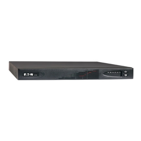
Spare Battery Kit, 12 Vdc Battery Kit, 750 and 1000 VA 103003732-5501 Spare Battery Kit, 24 Vdc Battery Kit, 1500 VA 103003733-5501 Spare Battery Kit, 36 Vdc Avaya Line Interactive RM UPS Site Preparation, Installation and Operator’s Manual 164201663 Rev 1... - Page 60 SPECIFICATIONS Table 4. Model List and Mechanical 120V Models 230V Models UPS Models PW5115 500 RM PW5115 500iRM PW5115 750 RM PW5115 750iRM PW5115 1000 RM PW5115 1000iRM PW5115 1500 RM PW5115 1500iRM UPS Dimensions (WxHxD) 44.0 x 4.45 x 57.8 cm (17.3″ x 1.75″ x 22.75″) UPS Weights 500 VA: 17.36 kg (38.2 lb)
- Page 61 EN 50091-1-1 and IEC 60950 Safety Markings cULus, cUL cULus, cUL, CE, TÜV EMC (Class B) FCC Part 15, ICES-003 EN 50091-2, FCC Part 15, ICES-003 Avaya Line Interactive RM UPS Site Preparation, Installation and Operator’s Manual 164201663 Rev 1...
- Page 62 Advanced monitoring for earlier failure detection and warning Battery Runtimes 5 minutes, typical at full load NOTE Battery times are approximate and may vary depending on the load configuration and battery charge. Avaya Line Interactive RM UPS Site Preparation, Installation and Operator’s Manual 164201663 Rev 1...
-
Page 63: Troubleshooting
(see Table 9). To silence the alarm for an existing fault, press the button. If UPS status changes, the alarm beeps, overriding the previous alarm silencing. Avaya Line Interactive RM UPS Site Preparation, Installation and Operator’s Manual 164201663 Rev 1... -
Page 64: Site Wiring Fault (120V Models Only)
Prepare your equipment for shutdown. If this is an extended power outage, save your work and turn off your equipment to conserve battery power. 1 beep every 4 seconds. Avaya Line Interactive RM UPS Site Preparation, Installation and Operator’s Manual 164201663 Rev 1... - Page 65 If the indicator still flashes, see “Replacing Batteries” on page 48 to replace the battery. Call your Avaya service representative if the problem Continuous beep. persists. UPS internal temperature Shutdown is imminent. Save your work and turn off is too high.
-
Page 66: Obtaining Service
The troubleshooting chart covers most of the difficulties you may encounter during normal operations. If you have any questions or problems with your UPS, call your Avaya service representative or the appropriate telephone number on the service label of your UPS. - Page 68 *1642016631* 164201663 Rev 1...