
Related Manuals for Emerson Keystone EPI2 63


Summary of Contents for Emerson Keystone EPI2 63
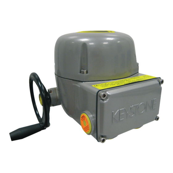
- Page 1 Installation, Operation and Maintenance Manual MAN-10-04-100-0711-EN Rev. 0 October 2020 Keystone EPI2 Electric Actuator...
- Page 2 Notes Installation, Operation and Maintenance Manual October 2020 MAN-10-04-100-0711-EN Rev. 0 This page intentionally left blank...
-
Page 3: Table Of Contents
Installation, Operation and Maintenance Manual Table of Contents MAN-10-04-100-0711-EN Rev. 0 October 2020 Table of Contents Section 1: General Safety Instructions Intended Use ....................1 Terms and Conditions ................. 2 Manufacturer's Liability ................2 Identification ....................3 1.4.1 Water - Dust-Proof Version ............... 3 1.4.2 Explosion-Proof Version .............. - Page 4 Table of Contents Installation, Operation and Maintenance Manual October 2020 MAN-10-04-100-0711-EN Rev. 0 Section 5: Lubrication Lubrication Inspection ................26 Section 6: Actuator Configuration Removal of the Control Unit Cover ............28 Local Configuration of the Keystone EPI2 ..........29 6.2.1 Keystone EPI2 Default General Configuration........
-
Page 5: Section 1: General Safety Instructions
Emerson Valves & Controls will not be liable for any possible damage or physical injury resulting from use in other than the designated applications or by lack of care during installation, operation, adjustment and maintenance of the machine. -
Page 6: Terms And Conditions
Terms and Conditions Emerson guarantees each single product to be free from defects and to conform to current goods specifications. The warranty period is one year from the date of installation by the first user, or eighteen months from the date of shipment to the first user, whichever occurs first. -
Page 7: Identification
Installation, Operation and Maintenance Manual Section 1: General Safety Instructions MAN-10-04-100-0711-EN Rev. 0 October 2020 Identification 1.4.1 Water - Dust-Proof Version Keystone EPI2 actuators are designed and manufactured according to EN 60529 standards. Specific types of protection are printed on the label, as follows: •... -
Page 8: Explosion-Proof Version
Section 1: General Safety Instructions Installation, Operation and Maintenance Manual October 2020 MAN-10-04-100-0711-EN Rev. 0 1.4.2 Explosion-Proof Version The version of Keystone EPI2 suitable for installation in hazardous areas is designed and manufactured according to EN 60079-0, EN 60079-1, EN IEC 60079-7, EN 60079-31 standards. Different types of protection are available, depending on the requirements of the installation site. - Page 9 Installation, Operation and Maintenance Manual Section 1: General Safety Instructions MAN-10-04-100-0711-EN Rev. 0 October 2020 Figure 2 Atex Label for Application in Hazardous Areas KEYSTONE A. Manufacturer logo B. Product model C. Nominal output torque value D. Product code E. Serial number F.
-
Page 10: Applicable Standards And Regulations
Section 1: General Safety Instructions Installation, Operation and Maintenance Manual October 2020 MAN-10-04-100-0711-EN Rev. 0 Applicable Standards and Regulations EN ISO 12100-1 Safety of machinery Basic concepts, general principles for design Part 1: Basic terminology, methodology EN ISO12100-2 Safety of machinery Basic concepts , general principles for design Part 2: Technical principles and specification EN 60204-1... -
Page 11: Section 2: Machine Description
Installation, Operation and Maintenance Manual Section 2: Machine Description MAN-10-04-100-0711-EN Rev. 0 October 2020 Section 2: Machine Description General The Keystone EPI2 is an electric quarter-turn actuator suitable to operate a valve in a 90° maneuver. Principle of Operation The electric motor drives the input to an epicyclical gear train via a spur reduction. The input member of the epicyclical gear train carries two compound planet gears which meshes with one internally toothed gears: the fixed annulus. -
Page 12: Manual Operation
Section 2: Machine Description Installation, Operation and Maintenance Manual October 2020 MAN-10-04-100-0711-EN Rev. 0 Manual Operation To be used in case of power supply failure or during actuator setting. The manual operating device is completely independent of the motor drive and can be operated at any time, whether or not the motor is running, without danger to the operator. -
Page 13: Optional Modules
Installation, Operation and Maintenance Manual Section 2: Machine Description MAN-10-04-100-0711-EN Rev. 0 October 2020 Optional Modules Keystone EPI2 actuators can be provided with several optional modules, as listed in the table below. Please refer to this table for possible combinations of available modules. Table 2. -
Page 14: Options Label
Section 2: Machine Description Installation, Operation and Maintenance Manual October 2020 MAN-10-04-100-0711-EN Rev. 0 Options Label A label is always provided with base actuators where optional modules will have to be checked out once they are installed after delivery at local organisations care. Figure 4 Options Label S/N:... -
Page 15: Section 3: Storage And Pre-Installation
The standard plastic plugs used to close the cable entries are not weather-proof, they just prevent the entry of undesired objects during transport. Emerson can not accept responsibility for deterioration caused on site when the covers are removed. -
Page 16: Storage For A Brief Period (Less Than One Year)
Section 3: Storage and Pre-Installation Installation, Operation and Maintenance Manual October 2020 MAN-10-04-100-0711-EN Rev. 0 3.2.2 Storage for a Brief Period (less than one year) 3.2.2.1 Indoor Storage • Make sure the actuators are kept in a dry place, laid on a wooden pallet (not directly on the floor surface) and protected from dust •... -
Page 17: Section 4: Installation
Installation, Operation and Maintenance Manual Section 4: Installation MAN-10-04-100-0711-EN Rev. 0 October 2020 Section 4: Installation Checks to be Performed Before Installation To assemble the actuator onto the valve proceed as follows: • Check that the coupling dimensions of the valve flange and stem, or of the relevant extension, meet the actuator coupling dimensions •... -
Page 18: Coupling Block
Installation, Operation and Maintenance Manual Section 4: Installation October 2020 MAN-10-04-100-0711-EN Rev. 0 Coupling Block The electric actuator is delivered with drive details and flange in accordance with the technical characteristics required by the customer, ready to be installed onto the valve. Only one insert is included in the actuator package delivered to end users. -
Page 19: Installation Of The Keystone Epi2 Unit Onto A Valve
Installation, Operation and Maintenance Manual Section 4: Installation MAN-10-04-100-0711-EN Rev. 0 October 2020 Installation of the Keystone EPI2 Unit onto a Valve Move the valve to the completely open position. Manually bring the Keystone EPI2 to the completely open position (verify the local mechanical indicator) and check the rotation direction of actuator and valve. -
Page 20: Setting Of The Angular Stroke: Mechanical Stops
Installation, Operation and Maintenance Manual Section 4: Installation October 2020 MAN-10-04-100-0711-EN Rev. 0 Setting of the Angular Stroke: Mechanical Stops It is important for the mechanical stops to end the angular stroke at both extreme valve positions (fully open and fully closed). The setting of the angular stroke is performed by adjusting the travel stop screw mounted on the actuator housing. -
Page 21: Electrical Connections
Installation, Operation and Maintenance Manual Section 4: Installation MAN-10-04-100-0711-EN Rev. 0 October 2020 Electrical Connections Before powering the actuator, check that the supply voltage details on the nameplate are correct for the plant. Access to terminals for electrical connections is through the terminal cover. - Page 22 Installation, Operation and Maintenance Manual Section 4: Installation October 2020 MAN-10-04-100-0711-EN Rev. 0 Table 3. Current Absorption - Single Phase and DC Voltage Current Absorption (A) Oper. Selected Model Time 24 V 48 V 90 V 110 V 230 V 264 V 24 V 48 V...
-
Page 23: Removal Of The Terminal Board Enclosure
Installation, Operation and Maintenance Manual Section 4: Installation MAN-10-04-100-0711-EN Rev. 0 October 2020 Removal of the Terminal Board Enclosure Using a 5 mm Allen key, loosen the four screws and remove the cover. Figure 9 Removal of the Terminal Board Enclosure WARNING Pay attention not to damage the joint surfaces of the cover. -
Page 24: Cables Connections
Installation, Operation and Maintenance Manual Section 4: Installation October 2020 MAN-10-04-100-0711-EN Rev. 0 4.10 Cables Connections Before applying voltage to the Keystone EPI2 check that the electrical parameters (supply voltage and current) shown on the nameplate and on the attached wiring diagram are correct for the installation. - Page 25 Installation, Operation and Maintenance Manual Section 4: Installation MAN-10-04-100-0711-EN Rev. 0 October 2020 Remove the plugs from the cable entries. For electrical connections use components (cable glands, cables, hoses, conduits) which meet the requirements and the applicable codes of the plant specifications (mechanical protection and/or explosionproof protection). Screw the cable glands (or the conduits) tightly into the threaded entries, in order to guarantee the weatherproof and explosionproof protection (when applicable).
-
Page 26: Base Wiring Diagram
Installation, Operation and Maintenance Manual Section 4: Installation October 2020 MAN-10-04-100-0711-EN Rev. 0 4.11 Base Wiring Diagram Figure 11 BLINKER LOCAL MONITOR SELECTOR RELAY RELAY CLC1 CLC2 OPC1 OPC2 36 32 33 34 20 21 22 23 24 25 26 27 28 29 30 31 Output contacts... -
Page 27: Cable Entries
Installation, Operation and Maintenance Manual Section 4: Installation MAN-10-04-100-0711-EN Rev. 0 October 2020 4.12 Cable Entries The sealing of cables and conduit entries should be carried out in accordance with National Standards or the Regulatory Authorities that have certified the actuators. This is particularly true for units that are certified for use in hazardous areas where the method of sealing must be to an approved standard, and cable glands, reducers, plugs and adapters must be approved and separately certified. -
Page 28: Safety Instructions For Installation In Hazardous Area
Installation, Operation and Maintenance Manual Section 4: Installation October 2020 MAN-10-04-100-0711-EN Rev. 0 4.13 Safety Instructions for Installation in Hazardous Area 4.13.1 Instructions for Explosion-Proof Enclosures NOTE Keystone EPI2 electric actuators must be installed and maintained according to the applicable Rules regarding the electrical installation in hazardous areas (other than mines) classified as zone 1 and/or 2 (gas) and zone 21 and/or 22 (dust) according to EN 60079-10 (hazardous area classification). - Page 29 NOTE Each time the covers are opened or removed the condition of the seals must be checked. In case the seals are replaced, original spares must be supplied by Emerson. NOTE Keystone EPI2 electric actuators must be installed and maintained according to the...
-
Page 30: Section 5: Lubrication
Installation, Operation and Maintenance Manual Section 5: Lubrication October 2020 MAN-10-04-100-0711-EN Rev. 0 Section 5: Lubrication Lubrication Inspection The actuator is grease lubricated for life, therefore under normal working conditions no grease needs to be replaced or added. In case of maintenance the following grease is recommended: •... -
Page 31: Section 6: Actuator Configuration
Installation, Operation and Maintenance Manual Section 6: Actuator Configuration MAN-10-04-100-0711-EN Rev. 0 October 2020 Section 6: Actuator Configuration Before connecting power to the actuator, check that the voltages are correct and according to the indications on the nameplate. Wrong power supply could cause permanent damage to the electrical components. -
Page 32: Removal Of The Control Unit Cover
Section 6: Actuator Configuration Installation, Operation and Maintenance Manual October 2020 MAN-10-04-100-0711-EN Rev. 0 Removal of the Control Unit Cover Using a 5 mm Allen key, loosen the four screws and remove the cover. NOTE When setting the actuator parameters do not operate the actuator neither remotely nor locally. WARNING Pay attention not to damage the joint surfaces of the cover. -
Page 33: Local Configuration Of The Keystone Epi2
Installation, Operation and Maintenance Manual Section 6: Actuator Configuration MAN-10-04-100-0711-EN Rev. 0 October 2020 Local Configuration of the Keystone EPI2 WARNING The configuration must be done while the actuator is powered on. As a consequence, all configuration operations must be carried out by specifically qualified personnel for operations on powered electronic cards. - Page 34 Section 6: Actuator Configuration Installation, Operation and Maintenance Manual October 2020 MAN-10-04-100-0711-EN Rev. 0 Figure 15 Configuration of the actuator parameters Table 5. Set-up Base Card Rotary switches position Dip switch Enter button Set-up Default Close limit PUSH n.d. Open limit PUSH n.d.
-
Page 35: Close Limit Configuration By Position
Installation, Operation and Maintenance Manual Section 6: Actuator Configuration MAN-10-04-100-0711-EN Rev. 0 October 2020 6.2.2 Close Limit Configuration by Position Enter set up configuration: • Move switch SW4 to position 2 • Move switch SW6 to position 1 • Move switch SW3 to position ON •... -
Page 36: Open Limit Configuration
Section 6: Actuator Configuration Installation, Operation and Maintenance Manual October 2020 MAN-10-04-100-0711-EN Rev. 0 6.2.5 Open Limit Configuration • Move switch SW3 to position ON • Drive the actuator to the open position using the handwheel • Move switch SW4 to position 1 •... -
Page 37: Stroking Time Selection In Closing
Installation, Operation and Maintenance Manual Section 6: Actuator Configuration MAN-10-04-100-0711-EN Rev. 0 October 2020 NOTE During the new stroke limit setup, the minimum range between open and close limit position has to be at least 45 degree of the valve position; if the above condition is not respected, the setup will not be successful and stroke limit error alarm will be signalized (red LED blinking). -
Page 38: Stroking Time Selection In Opening
Section 6: Actuator Configuration Installation, Operation and Maintenance Manual October 2020 MAN-10-04-100-0711-EN Rev. 0 6.2.9 Stroking Time Selection in Opening • Enter set up configuration: move switch SW3 to position ON (configuration function) • Move switch SW4 to position 5 •... -
Page 39: Configuration Of The Torque Limiting Device In Opening
Installation, Operation and Maintenance Manual Section 6: Actuator Configuration MAN-10-04-100-0711-EN Rev. 0 October 2020 6.2.11 Configuration of the Torque Limiting Device in Opening Opening torque limits: 50%, 75% and 100% of the nominal torque. The nominal torque corresponding to 100% is set in-house and stated in the name plate. •... -
Page 40: Actuator Model Selection
Section 6: Actuator Configuration Installation, Operation and Maintenance Manual October 2020 MAN-10-04-100-0711-EN Rev. 0 6.2.13 Actuator Model Selection The frames relevant to models 63/125 and 250/500 can be set to operate with a 63 Nm or 125 Nm motor and a 250 Nm or 500 Nm motor respectively. The difference is based on the technical characteristics of the electric motor itself. -
Page 41: Blinker / Local Selector Configuration
Installation, Operation and Maintenance Manual Section 6: Actuator Configuration MAN-10-04-100-0711-EN Rev. 0 October 2020 Actuator model 500, 1000, 2000 • Enter set up configuration: move switch SW3 to position ON (configuration function) • Move switch SW4 to position 9 • Move switch SW6 to position 1 •... -
Page 42: 3-Wires/2-Wires Remote Control Configuration
The relevant Instruction and Operating Manual is available with the ‘A Manager’ software. WARNING The controls available via Bluetooth allow full actuator operability at a distance. Emerson will not accept any responsibility for damages or injuries caused by an improper use of your Bluetooth PDA. Actuator Configuration... -
Page 43: Hardware Configuration For Monitor Relay
Installation, Operation and Maintenance Manual Section 6: Actuator Configuration MAN-10-04-100-0711-EN Rev. 0 October 2020 Hardware Configuration for Monitor Relay The Monitor Relay indicates the followings failures: • Loss of power • Stop by Torque out of limits • Direction failure •... -
Page 44: Section 7: Maintenance And Troubleshooting
Emerson with reference to the attached exploded view drawings and parts lists. It is essential that for every component to be required from Emerson the serial number of the actuator together with the item number of the component are indicated in the request. -
Page 45: Troubleshooting
Special maintenance is also recommended when, during operations, the actuator generates an excessive noise. Troubleshooting All Keystone EPI2 actuators have passed the functional test performed by Emerson Quality Assurance personnel. If the actuator does not work, before troubleshooting make sure that: •... -
Page 46: The Actuator Does Not Work From Remote Controls
Installation, Operation and Maintenance Manual Section 7: Maintenance and Troubleshooting October 2020 MAN-10-04-100-0711-EN Rev. 0 7.2.3 The Actuator does not work from Remote Controls Check that: • The wiring to terminals 32, 35 and 36 is correct • There is no short circuit between wires •... -
Page 47: Excessive Torque For Valve Operation
Installation, Operation and Maintenance Manual Section 7: Maintenance and Troubleshooting MAN-10-04-100-0711-EN Rev. 0 October 2020 7.2.7 Excessive Torque for Valve Operation • Clean, lubricate and check the valve stem • Valve packing too tight: loosen the gland bolt nuts • Check that the internal valve trim or the reducer gears are well lubricated and not damaged 7.2.8... -
Page 48: Section 8: Decommissioning
Installation, Operation and Maintenance Manual Section 8: Decommissioning October 2020 MAN-10-04-100-0711-EN Rev. 0 Section 8: Decommissioning Disposal and Recycling At the end of the life of Keystone EPI2, the device must be disassembled. Do not dump non-biodegradable products, lubricants and non-ferrous materials (rubber, PVC, resins etc.) into the environment. -
Page 49: Section 9: Parts List And Drawings
Installation, Operation and Maintenance Manual Section 9: Parts List and Drawings MAN-10-04-100-0711-EN Rev. 0 October 2020 Section 9: Parts List and Drawings This section includes the drawings and parts list of each component and subassembly of Keystone EPI2 actuators. NOTE When ordering spare parts, please indicate the serial number embossed on the actuator nameplate. - Page 50 Section 9: Parts List and Drawings Installation, Operation and Maintenance Manual October 2020 MAN-10-04-100-0711-EN Rev. 0 Table 9. Keystone EPI2 Model 063 - General Assembly Pos. Description Quantity Nut UNI 5588-M6 Nut UNI 5588-M8 Eccentric Planocentric gear Spacer Ball bearing type 16002 Ball bearing type 16004 Ball bearing type 6001 ESH screw UNI 5931-M6x8...
- Page 51 Installation, Operation and Maintenance Manual Section 9: Parts List and Drawings MAN-10-04-100-0711-EN Rev. 0 October 2020 Figure 16 Parts List and Drawings...
- Page 52 Section 9: Parts List and Drawings Installation, Operation and Maintenance Manual October 2020 MAN-10-04-100-0711-EN Rev. 0 Table 10. Keystone EPI2 Model 125 - General Assembly Pos. Description Quantity Nut UNI 5588-M6 Nut UNI 5588-M8 Eccentric Planocentric gear Spacer Ball bearing type 16002 Ball bearing type 16004 Ball bearing type 6001 ESH screw UNI 5931-M6x8...
- Page 53 Installation, Operation and Maintenance Manual Section 9: Parts List and Drawings MAN-10-04-100-0711-EN Rev. 0 October 2020 Figure 17 Parts List and Drawings...
- Page 54 Section 9: Parts List and Drawings Installation, Operation and Maintenance Manual October 2020 MAN-10-04-100-0711-EN Rev. 0 Table 11. Keystone EPI2 Model 250 - General Assembly Pos. Description Quantity Nut UNI 5588-M12 Nut UNI 5588-M6 Eccentric Planocentric gear Spacer Ball bearing type 6005 Ball bearing type 6202 Ball bearing type 16002 ESH screw UNI 5931-M6x8...
- Page 55 Installation, Operation and Maintenance Manual Section 9: Parts List and Drawings MAN-10-04-100-0711-EN Rev. 0 October 2020 Figure 18 Parts List and Drawings...
- Page 56 Section 9: Parts List and Drawings Installation, Operation and Maintenance Manual October 2020 MAN-10-04-100-0711-EN Rev. 0 Table 12. Keystone EPI2 Model 500 - General Assembly Pos. Description Quantity Nut UNI 5588-M12 Nut UNI 5588-M6 Eccentric Planocentric gear Spacer Ball bearing type 6005 Ball bearing type 6202 Ball bearing type 16002 ESH screw UNI 5931-M6x8...
- Page 57 Installation, Operation and Maintenance Manual Section 9: Parts List and Drawings MAN-10-04-100-0711-EN Rev. 0 October 2020 Figure 19 Parts List and Drawings...
- Page 58 Section 9: Parts List and Drawings Installation, Operation and Maintenance Manual October 2020 MAN-10-04-100-0711-EN Rev. 0 Table 13. Keystone EPI2 Model 1000 - General Assembly Pos. Description Quantity Nut UNI 5588-M16 Nut UNI 5588-M6 Eccentric Planocentric gear Spacer Ball bearing type 6305 Ball bearing type 16002 Ball bearing type NJ202ECP ESH screw UNI 5931-M6x8...
- Page 59 Installation, Operation and Maintenance Manual Section 9: Parts List and Drawings MAN-10-04-100-0711-EN Rev. 0 October 2020 Figure 20 Parts List and Drawings...
- Page 60 Section 9: Parts List and Drawings Installation, Operation and Maintenance Manual October 2020 MAN-10-04-100-0711-EN Rev. 0 Table 14. Keystone EPI2 Model 2000 (Gear Reducer) - General Assembly Pos. Description Quantity Nut M20 ISO 4032 EN 24032 Ball bearing type 6006 Ball bearing type 16004 Ball bearing type 61908 HSHC screw UNI 5931-M6x16...
- Page 61 Installation, Operation and Maintenance Manual Section 9: Parts List and Drawings MAN-10-04-100-0711-EN Rev. 0 October 2020 Figure 21 Parts List and Drawings...
- Page 62 Section 9: Parts List and Drawings Installation, Operation and Maintenance Manual October 2020 MAN-10-04-100-0711-EN Rev. 0 Table 15. Keystone EPI2 Model 2000 (Actuator) - General Assembly Pos. Description Quantity Nut UNI 5588-M6 Eccentric Planocentric gear Spacer Ball bearing type 6305 Ball bearing type 16002 Roller bearing type NJ202ECP ESH screw UNI 5931-M6x8...
- Page 63 Installation, Operation and Maintenance Manual Section 9: Parts List and Drawings MAN-10-04-100-0711-EN Rev. 0 October 2020 Figure 22 Parts List and Drawings...
- Page 64 P. R. China Székesfehérvár 8000 T +86 22 8212 3300 Hungary The Emerson logo is a trademark and service mark of Emerson Electric Co. T +36 22 53 09 50 Keystone is a mark of one of the Emerson family of companies.