Table of Contents
Advertisement
Quick Links
Instruction Manual
D104616X012
January 2023
LS200 Series Direct-Operated Regulators
Table of Contents
Introduction .................................................................. 1
Specifications .............................................................. 2
Principle of Operation .................................................. 7
Installation ................................................................... 8
Overpressure Protection.............................................. 8
Startup ......................................................................... 9
Adjustment .................................................................. 9
Shutdown................................................................... 10
Maintenance .............................................................. 10
Parts Ordering ........................................................... 12
Parts List.................................................................... 13
▲
Failure to follow these instructions or
to properly install and maintain this
equipment could result in an explosion,
fire and/or fire causing property damage
and personal injury or death.
Fisher™ regulators must be installed,
operated and maintained in accordance
with federal, state and local codes, rules
and regulations, and Emerson Process
Management Regulator Technologies Inc.
(Emerson) instructions.
If the regulator vents gas or a leak
develops in the system, service to
the unit may be required. Failure
to correct trouble could result in a
hazardous condition.
Call a qualified service person to service
the unit. Installation, operation and
maintenance procedures performed
by unqualified person may result
WARNING
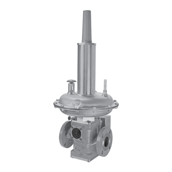
Figure 1. LS200 Series Regulator
in improper adjustment and unsafe
operation. Either condition may result in
equipment damage or personal injury.
Only a qualified person shall install or
service the regulator.
Introduction
Scope of the Manual
This manual provides specifications, installation,
adjustment, maintenance instructions and parts
ordering information for the LS200 Series Regulators.
Only personnel qualified through training or experience
should install, operate and maintain this regulator. If
there are any questions concerning these instructions,
contact your local Emerson Impact Partner Office
before proceeding.
LS200 Series
Advertisement
Table of Contents

Related Manuals for Emerson Fisher LS200 Series


Summary of Contents for Emerson Fisher LS200 Series
-
Page 1: Table Of Contents
If hazardous condition. there are any questions concerning these instructions, contact your local Emerson Impact Partner Office Call a qualified service person to service before proceeding. the unit. Installation, operation and... -
Page 2: Specifications
2. The pressure/temperature limits in this Instruction Manual and any applicable standard or code limitation should not be exceeded. 3. The lock up and function were tested to -40°F / -40°C. Flow performance was tested at ambient temperature. 4. Contact your Emerson Impact Partner or the local Emerson sales office for more information. PED Categories and Fluid Group Table 1. - Page 3 LS200 Series Table 2. Available Configurations TYPE NUMBER OPTION PRESSURE CONSTRUCTION Low Pressure Applications (In Development) Medium Pressure Applications (Outlet Pressure: 0.3 to 1.5 bar / 4.35 to 21.75 psig) High Pressure Applications (Outlet Pressure: 1.38 to 4.14 bar / 20 to 60 psig) OVERPRESSURE PROTECTION Without Overpressure Protection Module With Slam-shut Module...
- Page 4 LS200 Series Table 7. Pressure Ranges and Body Pressure-Temperature Ratings Without PED Certification MAXIMUM MAXIMUM BODY OUTLET RANGE TEMPERATURE RANGE BODY OPERATING INLET PRESSURE RATING TYPE MATERIAL CONNECTION psig ˚F ˚C psig psig -20 to 100 -29 to 38 PN 16 -20 to 150 -29 to 66 Ductile iron...
- Page 5 LS200 Series Table 8. Pressure Ranges and Body Pressure-Temperature Ratings With PED Certification MAXIMUM MAXIMUM BODY OUTLET RANGE TEMPERATURE RANGE BODY OPERATING INLET PRESSURE RATING TYPE MATERIAL CONNECTION psig ˚F ˚C psig psig -4 to 100 -20 to 38 PN 16 -4 to 140 -20 to 60 Ductile iron...
- Page 6 August 2022 LS200 Series Type LSR Medium Pressure Direct-Operated Regul INLET PRESSURE TYPE LS220 OUTLET PRESSURE TYPE LS250 ATMOSPHERIC PRESSURE INLET PRESSURE OUTLET PRESSURE ATMOSPHERIC PRESSURE Figure 2. LS200 Series Operational Schematics 5 x DN 10 x DN Figure 3a. LS200 Series Installation Schematic...
-
Page 7: Principle Of Operation
When the regulator is locked up, inlet pressure is registered on the top of the disk Emerson will not be responsible for any possible and on the bottom of the balancing diaphragm through inefficiency due to installation of non-Emerson space between the stem and cage. -
Page 8: Installation
LS200 Series ARMED ARMED RESET RESET TRIPPED TRIPPED ARMED REARMING Figure 4. Rearming Process Installation The regulator may be installed in any position as long as the flow through the body is the same as indicated by the flow direction arrow on the body and the vent ▲... -
Page 9: Startup
LS200 Series The regulator should be inspected for damage after should be checked periodically to be sure that the any overpressure condition. opening has not been plugged with foreign material. On some installations it may be necessary to provide Reset Procedure additional protection from the elements. -
Page 10: Shutdown
Only parts manufactured by Shutdown Emerson should be used for repairing Fisher™ regulators. Restart gas Isolate the regulator from the pressure system and utilization equipment according to normal release pressure from the outlet and the control line. - Page 11 LS200 Series force applied to it. Release the spring 6. Diaphragm (key 4) should now be loose and can compression as described in step 2 be replaced. of Actuator Maintenance and Balance 7. Align bolt holes before tightening down locknut Diaphragm Replacement.
-
Page 12: Parts Ordering
LS200 Series Replacing Orifice or Seat 10. Remove locknut (key 54) on the disk assembly (key 43) and remove disk. 1. Isolate the regulator and bleed downstream pressure to atmosphere. Once pressure upstream 11. Remove screws (key 34) then remove the orifice and downstream have bled to 0, manually trip the (key 38) and cage (key 35) from the intermediary slam-shut to release the spring energy in the trim. -
Page 13: Parts List
LS200 Series Parts List Description Part Number Description Part Number Spare Parts Kit See Repair Kit Table Hole Plug, Brass ERAA11283A0 Body See Key 1 Table Gasket, Nitrile (NBR) ERAA12018A0 Upper Casing, Steel Pad Retainer, Steel Types LS220 and LS224 ERAA10668A0 100% capacity, Types LS220 and LS224 ERAA51481A0... - Page 14 LS200 Series Repair Kit SPARE PART KITS ACTUATOR TYPE (SIZE) KIT PART NUMBER All (single side) 32, 42, 43, 54 RLS2PAD10A0 Pad Repair Kit All (double side) 32, 42, 43, 54 RLS2PAD20A0 32, 38, 40, 42, 54 RLS2ORFC0A0 Orifice Kit All with slam shut device 32, 38, 40, 42, 54, 203, 206, 207, 223 RLS24ORFCA0...
- Page 15 LS200 Series Key 1, Body Materials and Part Numbers BODY SIZE BODY MATERIAL END CONNECTION STYLE SLAM-SHUT POSITION PART NUMBER ERAA52444A0 ERAA52446A0 CL150 RF ERAA52448A0 L-R and R-L ERAA09111A0 Ductile iron ERAA52432A0 ERAA52445A0 PN 16 L-R and R-L ERAA09124A0 ERAA52447A0 ERAA52451A0 ERAA52452A0 CL150 RF...
- Page 16 LS200 Series PRESSURE LOADED OPTION (Ø 350) SECTION B-B APPLY LUBRICANT (L) L1 = GENERAL PURPOSE PTFE OR LITHIUM GREASE SECTION A-A L2 = ANTI-SEIZE COMPOUND L3 = THREAD LOCKER 1. Lubricants must be selected such that they meet the temperature requirements. Figure 5.
- Page 17 LS200 Series PRESSURE LOADED OPTION (Ø 255) SECTION B-B APPLY LUBRICANT (L) L1 = GENERAL PURPOSE PTFE OR LITHIUM GREASE L2 = ANTI-SEIZE COMPOUND L3 = THREAD LOCKER SECTION A-A 1. Lubricants must be selected such that they meet the temperature requirements. Figure 6.
- Page 18 LS200 Series 227 L1 202 L2 SECTION A-A 216 L3 SECTION B-B ARMED RESET TRIPPED SECTION C-C APPLY LUBRICANT (L) L1 = GENERAL PURPOSE PTFE OR LITHIUM GREASE L2 = ANTI-SEIZE COMPOUND L3 = THREAD LOCKER 1. Lubricants must be selected such that they meet the temperature requirements. Figure 7.
- Page 19 LS200 Series 202 L2 SECTION E-E SECTION F-F SECTION K APPLY LUBRICANT (L) L2 = ANTI-SEIZE COMPOUND L3 = THREAD LOCKER 1. Lubricants must be selected such that they meet the temperature requirements. Figure 7. LS200 Series Slam-Shut Device Assembly...
- Page 20 Technologies, Inc. All rights reserved. 12/22. Emerson Automation Solutions The Emerson logo is a trademark and service mark of Emerson Electric Co. All other marks are the property of their prospective owners. Fisher™ is a mark owned by Fisher Controls International LLC, a business...