
Related Manuals for Juniper JRR200


Summary of Contents for Juniper JRR200
- Page 1 JRR200 Route Reflector Hardware Guide Modified: 2018-08-15 Copyright © 2018, Juniper Networks, Inc.
- Page 2 END USER LICENSE AGREEMENT The Juniper Networks product that is the subject of this technical documentation consists of (or is intended for use with) Juniper Networks software. Use of such software is subject to the terms and conditions of the End User License Agreement (“EULA”) posted at https://www.juniper.net/support/eula/.
-
Page 3: Table Of Contents
JRR200 Route Reflector Physical Specifications ..... . . 21 JRR200 Route Reflector Cooling System ....... . . 21 JRR200 Route Reflector Air Flow and Cooling System . - Page 4 Replacing the JRR200 Route Reflector Fan Tray ..... . . 54 Maintaining the JRR200 Power System ....... . . 55 Maintaining the JRR200 Route Reflector Power Supplies .
- Page 5 Troubleshooting the JRR200 ........
- Page 6 Action to Take After an Electrical Accident ......106 JRR200 Agency Approvals and Regulatory Compliance Information ..106 Agency Approvals .
- Page 7 Overview ............17 Figure 1: JRR200 Route Reflector Front Panel ......18 Figure 2: JRR200 Route Reflector Chassis Status LEDs .
- Page 8 JRR200 Route Reflector Hardware Guide viii Copyright © 2018, Juniper Networks, Inc.
- Page 9 Table 3: JRR200 Route Reflector Components on the Front Panel ... . 18 Table 4: JRR200 Route Reflector Chassis Status LEDs ..... . 19 Table 5: Management Port LEDs .
- Page 10 JRR200 Route Reflector Hardware Guide Copyright © 2018, Juniper Networks, Inc.
-
Page 11: About The Documentation
® To obtain the most current version of all Juniper Networks technical documentation, see the product documentation page on the Juniper Networks website at https://www.juniper.net/documentation/ If the information in the latest release notes differs from the information in the documentation, follow the product Release Notes. -
Page 12: Table 1: Notice Icons
JRR200 Route Reflector Hardware Guide Table 1: Notice Icons Icon Meaning Description Informational note Indicates important features or instructions. Caution Indicates a situation that might result in loss of data or hardware damage. Warning Alerts you to the risk of personal injury or death. -
Page 13: Documentation Feedback
We encourage you to provide feedback, comments, and suggestions so that we can improve the documentation. You can provide feedback by using either of the following methods: Online feedback rating system—On any page of the Juniper Networks TechLibrary site , simply click the stars to rate the https://www.juniper.net/documentation/index.html content, and use the pop-up form to provide us with information about your experience. -
Page 14: Requesting Technical Support
7 days a week, 365 days a year. Self-Help Online Tools and Resources For quick and easy problem resolution, Juniper Networks has designed an online self-service portal called the Customer Support Center (CSC) that provides you with the following features: Find CSC offerings: https://www.juniper.net/customers/support/... - Page 15 About the Documentation For international or direct-dial options in countries without toll-free numbers, see https://www.juniper.net/support/requesting-support.html Copyright © 2018, Juniper Networks, Inc.
- Page 16 JRR200 Route Reflector Hardware Guide Copyright © 2018, Juniper Networks, Inc.
-
Page 17: Overview
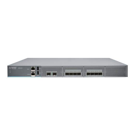
30 million routing information base (RIB) entries. The JRR200 route reflector comes with eight 1/10 Gigabit Ethernet SFP+ ports, 64 GB of DDR4 memory, and two 240-GB solid-state drives (SSDs) in a RAID1 configuration. The... -
Page 18: Jrr200 Chassis
JRR200 route reflector. Figure 1: JRR200 Route Reflector Front Panel Table 3 on page 18 lists the components on the front panel of the JRR200 route reflector. Table 3: JRR200 Route Reflector Components on the Front Panel Number... -
Page 19: Jrr200 Route Reflector Chassis Status Leds
LEDs that are located on the front panel of the JRR200 route reflector. Table 4 on page 19 describes the LEDs. Figure 2: JRR200 Route Reflector Chassis Status LEDs Power Status Table 4: JRR200 Route Reflector Chassis Status LEDs... -
Page 20: Network Port Leds
Table 7: JRR200 Route Reflector Rear Panel Components Number Component Description Grounding point Connects the JRR200 route reflector chassis to earth ground. Power switch Use the Power switch to power on or power off the JRR200 route reflector. Copyright © 2018, Juniper Networks, Inc. -
Page 21: Jrr200 Route Reflector Physical Specifications
JRR200 route reflector with 2 AC power supplies: 29 lb (13.16 kg) JRR200 route reflector with 2 DC power supplies: 28.8 lb (13.06 kg) You can mount the JRR200 route reflector on a standard 19-in. four-post rack or in a standard 19-in. enclosed cabinet. -
Page 22: Jrr200 Route Reflector Air Flow And Cooling System
22. The airflow produced by the fans keeps device components within the acceptable temperature range. If any one of the four fan trays fails, the JRR200 route reflector generates a warning but keeps the system running. If the temperature keeps rising, the JRR200 route reflector lowers the power consumption by reducing the performance or shutting down some of the chassis components. -
Page 23: Jrr200 Route Reflector Ac Power Supply
The AC power supply unit is a field-replaceable unit (FRU) and you can install it without powering off the JRR200 route reflector or disrupting the route reflector function. If one power supply unit fails or is removed, the other power supply unit redistributes the electrical load without interruption. -
Page 24: Jrr200 Route Reflector Ac Power Supply Specifications
If the AC LED is lit and the DC LED is unlit, the AC power supply unit is installed properly, but the power supply unit has an internal failure. JRR200 Route Reflector AC Power Supply Specifications Table 10 on page 24 lists the specifications for an AC power supply. -
Page 25: Jrr200 Route Reflector Ac Power Cord Specifications
Power Requirement ) * 3.41 Note: 1 W = 3.41 BTU/Hour JRR200 Route Reflector AC Power Cord Specifications A detachable AC power cord is supplied with the AC power supplies. The coupler is type C13 as described by International Electrotechnical Commission (IEC) standard 60320. -
Page 26: Jrr200 Route Reflector Dc Power Supply
The DC power supply unit is a field-replaceable unit (FRU) and you can install it without powering off the JRR200 route reflector or disrupting the route reflector function. If one power supply unit fails or is removed, the other power supply unit redistributes the electrical load without interruption. -
Page 27: Jrr200 Route Reflector Dc Power Supply Specifications
Blinking Invalid power supply unit. Unlit Power supply unit is functioning normally. JRR200 Route Reflector DC Power Supply Specifications Table 13 on page 27 lists the power supply specifications for a DC power supply. Table 13: DC Power Supply Specifications... - Page 28 JRR200 Route Reflector Hardware Guide Copyright © 2018, Juniper Networks, Inc.
-
Page 29: Site Planning, Preparation, And Specifications
CHAPTER 2 Site Planning, Preparation, and Specifications Site Preparation Checklist for the JRR200 Route Reflector on page 29 JRR200 Site Guidelines and Requirements on page 30 JRR200 Rack and Cabinet Requirements on page 34 JRR200 Network Cable and Transceiver Planning on page 35... -
Page 30: Jrr200 Site Guidelines And Requirements
JRR200 Route Reflector Hardware Guide Table 14: Site Preparation Checklist for JRR200 Route Reflector (continued) Additional Performed Item or Task Information Date Notes Rack or Cabinet Verify that your rack or cabinet meets the “JRR200 Rack and minimum requirements for the installation Cabinet of the device. -
Page 31: General Site Guidelines
Table 16 on page 32 describes the factors you must consider while planning the electrical wiring at your site. WARNING: It is particularly important to provide a properly grounded and shielded environment and to use electrical surge-suppression devices. Copyright © 2018, Juniper Networks, Inc. -
Page 32: Clearance Requirements For Jrr200 Route Reflector Airflow And Hardware Maintenance
General Safety Guidelines and Warnings on page 76 General Electrical Safety Guidelines and Warnings on page 96 Clearance Requirements for JRR200 Route Reflector Airflow and Hardware Maintenance When planning the installation site, you need to allow sufficient clearance around the JRR200 Route Reflector. -
Page 33: Figure 11: Airflow Through The Chassis
Chapter 2: Site Planning, Preparation, and Specifications Figure 11: Airflow Through the Chassis If you are mounting the JRR200 route reflector on a rack or cabinet along with other equipment, ensure that the exhaust from other equipment does not blow into the intake vents of the chassis. -
Page 34: Jrr200 Rack And Cabinet Requirements
Secure the rack to the ceiling brackets as well for maximum stability. JRR200 Route Reflector Cabinet Requirements You can install the JRR200 Route Reflector in a 19 in. (48.7 cm) cabinet. Table 19 on page 35 provides the cabinet requirements and specifications. -
Page 35: Jrr200 Network Cable And Transceiver Planning
Cabinet Requirement Guideline Cabinet size You can mount the JRR200 route reflector in a cabinet that contains a 19-in. rack as defined in Cabinets, Racks, Panels, and Associated Equipment (document number EIA-310–D) published by the Electronics Industry http://www.ecianow.org/standards-practices/standards/ Association (... -
Page 36: Sfp+ Direct Attach Copper Cables For Jrr200 Route Reflector
23 ft (7 m), making them ideal for highly cost-effective networking connectivity within a rack and between adjacent racks. The JRR200 Route Reflector supports the following 1 m and 3 m long DAC cables: SRX-SFP-10GE-DAC-1M... -
Page 37: Reflector
Chapter 2: Site Planning, Preparation, and Specifications Console Port Connector Pinout Information for the JRR200 Route Reflector The console port is an RS-232 serial interface that uses an RJ-45 connector to connect to a console management device. The default baud rate for the console port is 9600 baud. - Page 38 JRR200 Route Reflector Hardware Guide Copyright © 2018, Juniper Networks, Inc.
-
Page 39: Initial Installation And Configuration
Performing the Initial Configuration for JRR200 on page 48 JRR200 Route Reflector Installation Overview Installing and Connecting an JRR200 Route Reflector Installation Overview on page 39 Installing and Connecting an JRR200 Route Reflector Installation Overview To install and connect a JRR200 Route Reflector: Follow instructions in “Unpacking the JRR200”... -
Page 40: Unpacking The Jrr200
Verifying Parts Received with the JRR200 Route Reflector on page 40 Unpacking the JRR200 Route Reflector The JRR200 Route Reflector is shipped in a cardboard carton, secured with foam packing material. The carton also contains an accessory box and quick-start instructions. -
Page 41: Installing The Jrr200 Route Reflector In A Rack
(The remainder of this topic uses rack to mean rack or cabinet.) Before mounting the JRR200 route reflector on four posts in a rack: Verify that the site meets the requirements described in “Site Preparation Checklist for the JRR200 Route Reflector”... -
Page 42: Figure 12: Attaching The Mounting Ears And Fixed Brackets
Have one person grasp both sides of the JRR200 route reflector, lift it, and position it in the rack so that the front mounting bracket holes align with the threaded holes in... -
Page 43: Connecting The Jrr200 To Power
Chapter 3: Initial Installation and Configuration Figure 13: Securing the Mounting Ears to the Rack Continue to support the JRR200 route reflector, and have the second person slide the rear mounting blades into the channels of the side mounting rails and secure the blades to the rack. -
Page 44: Connecting Power To An Ac-Powered Jrr200 Route Reflector
Connecting Power to an AC-Powered JRR200 Route Reflector Ensure that you have a power cord appropriate for your geographical location available to connect AC power to the JRR200 Route Reflector. Before you begin connecting AC power: Ensure that you have taken the necessary precautions to prevent electrostatic discharge (ESD) damage. - Page 45 If the AC power source outlet has a power switch, set it to on (|) position. Set the power switch on the JRR200 route reflector to the on (|) position and it will power If there is no power switch on the AC power source outlet, set the power switch on the JRR200 route reflector to the on (|) position and it will power on.
-
Page 46: Connecting Power To A Dc-Powered Jrr200 Route Reflector
JRR200 Route Reflector Hardware Guide Connecting Power to a DC-Powered JRR200 Route Reflector Before you begin connecting DC power to a JRR200 Route Reflector: Ensure that you have taken the necessary precautions to prevent electrostatic discharge (ESD) damage. Ensure that you have connected the chassis to earth ground. -
Page 47: Connecting Jrr200 Route Reflector To External Devices
Switch the circuit breaker to the ON (|) position. Verify that the LEDs on the power supply are lit green and are on steadily. Connecting JRR200 Route Reflector to External Devices Connecting JRR200 Route Reflector to Management Devices on page 48 Copyright © 2018, Juniper Networks, Inc. -
Page 48: Connecting Jrr200 Route Reflector To Management Devices
JRR200 Route Reflector Hardware Guide Connecting JRR200 Route Reflector to Management Devices To configure the JRR200 route reflector, you must connect a management device to the CONSOLE port located on the front panel of the JRR200 route reflector, using the provided RJ-45-to-DB-9 adapter and the RJ45 cable. -
Page 49: Jrr200 Route Reflector Initial Configuration Using The Cli
Junos. By default, the management network interface ( ) is configured with DHCP enabled. If there is a DHCP server on the management network, then the JRR200 management network interface is automatically assigned an IP address. If there is no... -
Page 50: Jrr200 Route Reflector Factory-Default Settings
JRR200 Route Reflector Factory-Default Settings Your JRR200 route reflector comes configured with a factory-default configuration which has the ZTP configurations enabled when the JRR200 route reflector is shipped. The below is the factory default configuration file of JRR200 route reflector. - Page 51 0 { family inet { dhcp; interfaces { em9 { unit 0 { family inet { dhcp; chassis { auto-image-upgrade; system { processes { dhcp-service { traceoptions { file dhcp_logfile size 10m; level all; Copyright © 2018, Juniper Networks, Inc.
-
Page 52: Viewing Factory-Default Settings Of Jrr200 Route Reflector
JRR200 Route Reflector Hardware Guide flag all; Viewing Factory-Default Settings of JRR200 Route Reflector To view the factory-default settings on your JRR200 route reflector: Log in as the root user and provide your credentials. View the list of default config files: user@host>file list /etc/config... -
Page 53: Maintaining Components
For optimum cooling, verify the condition of the fan trays. Action Monitor the status of the fan trays. All the fan trays work in unison to cool the JRR200 route reflector. If one fan trayfails, the redundant fan tray acts as a backup. A major... -
Page 54: Replacing The Jrr200 Route Reflector Fan Tray
Spinning at normal speed Replacing the JRR200 Route Reflector Fan Tray Each fan tray is a field-replaceable unit (FRU) installed in the rear panel of JRR200 route reflector. You can remove and replace the fan trays without powering off JRR200 route reflector or disrupting route reflector functions. -
Page 55: Maintaining The Jrr200 Power System
Maintaining the JRR200 Power System Maintaining the JRR200 Route Reflector Power Supplies on page 55 Replacing the JRR200 Route Reflector AC Power Supply on page 56 Replacing the JRR200 Route Reflector DC Power Supply on page 58 Maintaining the JRR200 Route Reflector Power Supplies Purpose For optimum performance, verify the condition of the power supplies. -
Page 56: Replacing The Jrr200 Route Reflector Ac Power Supply
Replacing the JRR200 Route Reflector AC Power Supply Each AC power supply is a field-replaceable unit (FRU) installed in the rear panel of JRR200 route reflector. You can remove and replace the power supplies without powering off JRR200 route reflector or disrupting route reflector functions. -
Page 57: Installing A Jrr200 Route Reflector Ac Power Supply
Using both hands, place the power supply in the power supply slot on the rear panel of the JRR200 route reflector and slide it in until it is fully seated and the ejector lever fits into place. You will hear a distinct click when the power supply is fully seated in the chassis. -
Page 58: Replacing The Jrr200 Route Reflector Dc Power Supply
Replacing the JRR200 Route Reflector DC Power Supply Each DC power supply is a field-replaceable unit (FRU) installed in the rear panel of JRR200 route reflector. You can remove and replace the power supplies without powering off JRR200 route reflector or disrupting route reflector functions. -
Page 59: Installing A Jrr200 Route Reflector Dc Power Supply
Place the power supply in the antistatic bag or on the antistatic mat placed on a flat, stable surface. Installing a JRR200 Route Reflector DC Power Supply Ensure that you have the following parts and tools available: ESD grounding strap CAUTION: Do not mix AC and DC power supplies in the same chassis. -
Page 60: Maintaining The Jrr200 Cables And Connectors
Figure 19: Installing a DC Power Supply Maintaining the JRR200 Cables and Connectors Maintaining JRR200 Route Reflector Network Cables on page 60 Replacing an SFP+ Transceiver on JRR200 Route Reflector on page 61 Maintaining JRR200 Route Reflector Network Cables Purpose For optimum performance, verify the condition of the network cables. -
Page 61: Replacing An Sfp+ Transceiver On Jrr200 Route Reflector
Opptex Cletop-S Fiber Cleaner. Follow the directions for the cleaning kit you use. Replacing an SFP+ Transceiver on JRR200 Route Reflector Small form-factor pluggable plus transceivers (SFP+) are enhanced SFP transceivers that provides support for data rates of up to 10 Gbps for fiber-optic or copper interfaces. -
Page 62: Installing An Sfp+ Transceiver
JRR200 Route Reflector Hardware Guide Remove the cable connector from the transceiver. Immediately cover the transceiver and the end of the cable with a rubber safety cap. WARNING: Do not look directly into a fiber-optic transceiver or into the ends of fiber-optic cables. Fiber-optic transceivers and fiber-optic cable connected to a transceiver emit laser light that can damage your eyes. - Page 63 Do not look directly into a fiber-optic transceiver or into the ends of fiber-optic cables. Fiber-optic transceivers and fiber-optic cable connected to a transceiver emit laser light that can damage your eyes. See Also Removing an SFP+ Transceiver on page 61 Copyright © 2018, Juniper Networks, Inc.
- Page 64 JRR200 Route Reflector Hardware Guide Copyright © 2018, Juniper Networks, Inc.
-
Page 65: Troubleshooting Hardware
JTAC. Chassis Component Alarm Conditions on JRR200 Route Reflector You can monitor chassis alarms through the Status LED. When the JRR200 route reflector detects an alarm condition, the Status LED on the front panel glows red. The level of severity can be either major (steady red) or minor (blinking red). -
Page 66: Table 23: Alarms For Jrr200 Route Reflector Chassis Components
JRR200 Route Reflector Hardware Guide Table 23: Alarms for JRR200 Route Reflector Chassis Components Component Alarm Conditions Action Alarm Severity At least one of the fans have Check and adjust the room Steady red (major) failed. temperature, if possible. Check the air flow and ensure that the airflow through JRR200 route reflector is unobstructed. -
Page 67: Troubleshooting Hardware
Chapter 5: Troubleshooting Hardware Table 23: Alarms for JRR200 Route Reflector Chassis Components (continued) Component Alarm Conditions Action Alarm Severity Power supply A power supply has failed. Replace the power supply. Steady red (major) A power supply unit is not Install a power supply unit in the present. - Page 68 JRR200 Route Reflector Hardware Guide Table 23: Alarms for JRR200 Route Reflector Chassis Components (continued) Component Alarm Conditions Action Alarm Severity Mix of AC and DC power Check if all the power supplies Yellow (minor) supplies installed. installed are of the same type.
-
Page 69: Components
Networks on page 69 Listing the JRR200 Route Reflector Component Details with the CLI on page 70 Locating the Serial Number on the JRR200 Route Reflector or Component on page 70 Contacting Customer Support on page 71 Packing a JRR200 Route Reflector or its Components for Shipping on page 71... -
Page 70: Listing The Jrr200 Route Reflector Component Details With The Cli
Before contacting Juniper Networks to request a Return Materials Authorization (RMA), you must find the serial number on the JRR200 route reflector or component. To list all the JRR200 route reflector components and their serial numbers, enter the following CLI command: user@host>... -
Page 71: Locating The Chassis Serial Number Id Label
Chapter 6: Contacting Customer Support and Returning the Chassis or Components Locating the Chassis Serial Number ID Label The serial number ID label is located on the rear panel of the JRR200 route reflector. Locating the Serial Number ID Labels on FRUs The power supplies and fan trays installed in the JRR200 route reflector are field-replaceable units (FRUs). -
Page 72: Packing The Jrr200 Route Reflector For Shipment
Disconnect power from the JRR200 route reflector. Remove the cables that connect to all external devices. If the JRR200 route reflector is installed in a rack, have one person support the weight of the route reflector while another person unscrews and removes the mounting screws. -
Page 73: Packing The Jrr200 Route Reflector Components For Shipment
Write the Return Materials Authorization (RMA) number on the exterior of the box to ensure proper tracking. Packing the JRR200 Route Reflector Components for Shipment Follow these guidelines for packing and shipping individual components of the JRR200 route reflector: When you return a component, make sure that it is adequately protected with packing materials and packed so that the pieces are prevented from moving around inside the carton. - Page 74 JRR200 Route Reflector Hardware Guide Copyright © 2018, Juniper Networks, Inc.
-
Page 75: Safety And Compliance Information
Multiple Power Supplies Disconnection Warning on page 104 TN Power Warning on page 105 Action to Take After an Electrical Accident on page 106 JRR200 Agency Approvals and Regulatory Compliance Information on page 106 Copyright © 2018, Juniper Networks, Inc. -
Page 76: General Safety Guidelines And Warnings
JRR200 Route Reflector Hardware Guide General Safety Guidelines and Warnings The following guidelines help ensure your safety and protect the device from damage. The list of guidelines might not address all potentially hazardous situations in your working environment, so be alert and exercise good judgment at all times. -
Page 77: Definitions Of Safety Warning Levels
Avant de travailler sur un équipement, soyez conscient des dangers posés par les circuits électriques et familiarisez-vous avec les procédures couramment utilisées pour éviter les accidents. Copyright © 2018, Juniper Networks, Inc. -
Page 78: Restricted Access Warning
JRR200 Route Reflector Hardware Guide Warnung Dieses Warnsymbol bedeutet Gefahr. Sie befinden sich in einer Situation, die zu einer Körperverletzung führen könnte. Bevor Sie mit der Arbeit an irgendeinem Gerät beginnen, seien Sie sich der mit elektrischen Stromkreisen verbundenen Gefahren und der Standardpraktiken zur Vermeidung von Unfällen bewußt. - Page 79 Varning! Denna enhet är avsedd för installation i områden med begränsat tillträde. Ett område med begränsat tillträde får endast tillträdas av servicepersonal med ett speciellt verktyg, lås och nyckel, eller annan Copyright © 2018, Juniper Networks, Inc.
-
Page 80: Fire Safety Requirements
To keep warranties effective, do not use a dry chemical fire extinguisher to control a fire at or near a Juniper Networks device. If a dry chemical fire extinguisher is used, the unit is no longer eligible for coverage under a service agreement. -
Page 81: Qualified Personnel Warning
PTX3000 DC Power Electrical Safety Guidelines PTX5000 DC Power Electrical Safety Guidelines Warning Statement for Norway and Sweden WARNING: The equipment must be connected to an earthed mains socket-outlet. Advarsel Apparatet skal kobles til en jordet stikkontakt. Copyright © 2018, Juniper Networks, Inc. -
Page 82: Installation Instructions Warning
JRR200 Route Reflector Hardware Guide Varning! Apparaten skall anslutas till jordat nätuttag. Installation Instructions Warning WARNING: Read the installation instructions before you connect the device to a power source. Waarschuwing Raadpleeg de installatie-aanwijzingen voordat u het systeem met de voeding verbindt. -
Page 83: Ramp Warning
The device must be installed in a rack that is secured to the building structure. The device should be mounted at the bottom of the rack if it is the only unit in the rack. Copyright © 2018, Juniper Networks, Inc. - Page 84 Les directives ci-dessous sont destinées à assurer la protection du personnel: Le rack sur lequel est monté le Juniper Networks switch doit être fixé à la structure du bâtiment. Si cette unité constitue la seule unité montée en casier, elle doit être placée dans le bas.
- Page 85 Le seguenti direttive vengono fornite per garantire la sicurezza personale: Il Juniper Networks switch deve essere installato in un telaio, il quale deve essere fissato alla struttura dell'edificio. Questa unità deve venire montata sul fondo del supporto, se si tratta dell'unica unità...
- Page 86 Para garantizar su seguridad, proceda según las siguientes instrucciones: El Juniper Networks switch debe instalarse en un bastidor fijado a la estructura del edificio. Colocar el equipo en la parte inferior del bastidor, cuando sea la única unidad en el mismo.
-
Page 87: Grounded Equipment Warning
Chapter 7: Safety and Compliance Information Juniper Networks switch måste installeras i en ställning som är förankrad i byggnadens struktur. Om denna enhet är den enda enheten på ställningen skall den installeras längst ned på ställningen. Om denna enhet installeras på en delvis fylld ställning skall ställningen fyllas nedifrån och upp, med de tyngsta enheterna längst ned på... -
Page 88: Laser And Led Safety Guidelines And Warnings
JRR200 Route Reflector Hardware Guide Laser and LED Safety Guidelines and Warnings Juniper Networks devices are equipped with laser transmitters, which are considered a Class 1 Laser Product by the U.S. Food and Drug Administration and are evaluated as a Class 1 Laser Product per EN 60825-1 requirements. -
Page 89: Class 1 Led Product Warning
Avvertenza Non fissare il raggio con gli occhi né usare strumenti ottici per osservarlo direttamente. Advarsel Stirr eller se ikke direkte p strlen med optiske instrumenter. Aviso Não olhe fixamente para o raio, nem olhe para ele directamente com instrumentos ópticos. Copyright © 2018, Juniper Networks, Inc. -
Page 90: Radiation From Open Port Apertures Warning
JRR200 Route Reflector Hardware Guide ¡Atención! No mirar fijamente el haz ni observarlo directamente con instrumentos ópticos. Varning! Rikta inte blicken in mot strålen och titta inte direkt på den genom optiska instrument. Radiation from Open Port Apertures Warning WARNING:... -
Page 91: Maintenance And Operational Safety Guidelines And Warnings
Eliminare le batterie usate secondo le istruzioni del produttore. Aviso Existe perigo de explosão se a bateria for substituída incorrectamente. Substitua a bateria por uma bateria igual ou de um tipo equivalente Copyright © 2018, Juniper Networks, Inc. -
Page 92: Jewelry Removal Warning
JRR200 Route Reflector Hardware Guide recomendado pelo fabricante. Destrua as baterias usadas conforme as instruções do fabricante. ¡Atención! Existe peligro de explosión si la batería se reemplaza de manera incorrecta. Reemplazar la batería exclusivamente con el mismo tipo o el equivalente recomendado por el fabricante. -
Page 93: Lightning Activity Warning
Advarsel Utfør aldri arbeid på systemet, eller koble kabler til eller fra systemet når det tordner eller lyner. Aviso Não trabalhe no sistema ou ligue e desligue cabos durante períodos de mau tempo (trovoada). Copyright © 2018, Juniper Networks, Inc. -
Page 94: Operating Temperature Warning
6 in. (15.2 cm) of clearance around the ventilation openings. Waarschuwing Om te voorkomen dat welke switch van de Juniper Networks router dan ook oververhit raakt, dient u deze niet te bedienen op een plaats waar de maximale aanbevolen omgevingstemperatuur van 40°... -
Page 95: Product Disposal Warning
15,2 cm à volta das aberturas de ventilação. ¡Atención! Para impedir que un encaminador de la serie Juniper Networks switch se recaliente, no lo haga funcionar en un área en la que se supere la temperatura ambiente máxima recomendada de 40°... -
Page 96: General Electrical Safety Guidelines And Warnings
JRR200 Route Reflector Hardware Guide General Electrical Safety Guidelines and Warnings WARNING: Certain ports on the device are designed for use as intrabuilding (within-the-building) interfaces only (Type 2 or Type 4 ports as described in GR-1089-CORE) and require isolation from the exposed outside plant (OSP) cabling. -
Page 97: Prevention Of Electrostatic Discharge Damage
(see Figure 21 on page 98). If you are returning a component, place it in an antistatic bag before packing it. Copyright © 2018, Juniper Networks, Inc. -
Page 98: Ac Power Electrical Safety Guidelines
JRR200 Route Reflector Hardware Guide Figure 21: Placing a Component into an Antistatic Bag CAUTION ELECTROSTATIC SENSITIVE DEVICES DO NOT OPEN OR HANDLE EXCEPT AT A STATIC-FREE WORKSTATION CAUTION: ANSI/TIA/EIA-568 cables such as Category 5e and Category 6 can get electrostatically charged. To dissipate this charge, always ground the cables to a suitable and safe earth ground before connecting them to the system. -
Page 99: Ac Power Disconnection Warning
¡Atención! Antes de manipular el chasis de un equipo o trabajar cerca de una fuente de alimentación, desenchufar el cable de alimentación en los equipos de corriente alterna (CA). Copyright © 2018, Juniper Networks, Inc. -
Page 100: Dc Power Disconnection Warning
JRR200 Route Reflector Hardware Guide Varning! Innan du arbetar med ett chassi eller nära strömförsörjningsenheter skall du för växelströmsenheter dra ur nätsladden. DC Power Disconnection Warning WARNING: Before performing any of the DC power procedures, ensure that power is removed from the DC circuit. To ensure that all power is off, locate... -
Page 101: Dc Power Grounding Requirements And Warning
Avvertenza In fase di installazione dell'unità, eseguire sempre per primo il collegamento a massa e disconnetterlo per ultimo. Advarsel Når enheten installeres, må jordledningen alltid tilkobles først og frakobles sist. Copyright © 2018, Juniper Networks, Inc. -
Page 102: Dc Power Wiring Sequence Warning
JRR200 Route Reflector Hardware Guide Aviso Ao instalar a unidade, a ligação à terra deverá ser sempre a primeira a ser ligada, e a última a ser desligada. ¡Atención! Al instalar el equipo, conectar la tierra la primera y desconectarla la última. -
Page 103: Dc Power Wiring Terminations Warning
Attention Quand des fils torsadés sont nécessaires, utiliser des douilles terminales homologuées telles que celles à circuit fermé ou du type à plage ouverte avec cosses rebroussées. Ces douilles terminales doivent être de la Copyright © 2018, Juniper Networks, Inc. -
Page 104: Multiple Power Supplies Disconnection Warning
JRR200 Route Reflector Hardware Guide taille qui convient aux fils et doivent être refermées sur la gaine isolante et sur le conducteur. Warnung Wenn Litzenverdrahtung erforderlich ist, sind zugelassene Verdrahtungsabschlüsse, z.B. für einen geschlossenen Regelkreis oder gabelförmig, mit nach oben gerichteten Kabelschuhen zu verwenden. Diese Abschlüsse sollten die angemessene Größe für die Drähte haben und sowohl... -
Page 105: Tn Power Warning
Attention Ce dispositif a été conçu pour fonctionner avec des systèmes d'alimentation TN. Warnung Das Gerät ist für die Verwendung mit TN-Stromsystemen ausgelegt. Avvertenza Il dispositivo è stato progettato per l'uso con sistemi di alimentazione TN. Advarsel Utstyret er utfomet til bruk med TN-strømsystemer. Copyright © 2018, Juniper Networks, Inc. -
Page 106: Action To Take After An Electrical Accident
Acoustic Noise Compliance Statements on page 107 EMC Requirements on page 108 Agency Approvals The JRR200 Route Reflector complies with the following standards: Safety CAN/CSA C22.2 No. 60950-1-07, 2nd Edition, 2014-10 EN 60950-1:2006 + A11:2009 + A1:2010 + A12:2011 + A2:2013... -
Page 107: Acoustic Noise Compliance Statements
Acoustic Noise Compliance Statements The maximum emitted sound pressure level is 70 dB(A) or less per EN ISO 7779. German Translation: Maschinenlärminformations-Verordnung - 3. GPSGV, der höchste Schalldruckpegel beträgt 70 dB(A) oder weniger gemäss EN ISO 7779. Copyright © 2018, Juniper Networks, Inc. -
Page 108: Emc Requirements
VCCI-A United States The JRR200 Route Reflector has been tested and found to comply with the limits for a Class A digital device of the FCC Rules. These limits are designed to provide reasonable protection against harmful interference when the equipment is operated in a commercial environment.