PRESONUS StudioLive III Series Owner's Manual
Digital mix console / recorder with motorized faders
Hide thumbs
Also See for StudioLive III Series:
- Owner's manual (232 pages) ,
- Quick start manual (20 pages) ,
- Networking manual (17 pages)

Related Manuals for PRESONUS StudioLive III Series


Summary of Contents for PRESONUS StudioLive III Series
- Page 1 StudioLive Series III ™ Digital Mix Console / Recorder with Motorized Faders Owner’s Manual ® English www.presonus.com...
-
Page 2: Table Of Contents
Introduction — 1 Channel Strip Basics — 22 About this Manual — 1 Fader Layers and Banks — 23 Companion PreSonus Products — 2 4.2.1 User Fader Layer — 24 What’s in the Box — 3 Filter DCA Groups — 25 Additional Resources —... - Page 3 The Fat Channel — 43 Tape Controls — 73 Overview — 43 Pairing a Bluetooth Device — 73 6.1.1 A/B Comparison for EQ SD Recording — 74 and Dynamics Settings — 44 Creating a New Session for Recording — 74 Copy/Paste &...
- Page 4 Monitoring Controls — 98 Resources — 121 10.1 Solo Controls — 98 13.1 Networking Overview — 121 10.1.1 Solo Modes — 99 13.1.1 Wired Ethernet Control Setup — 121 10.1.2 Using the Solo Bus for 13.2 Stereo Microphone Placement — 123 Monitoring —...
- Page 5 13.9 Effect Types — 138 13.9.1 Reverb and its Parameters — 138 13.9.2 Delay and its Parameters — 139 13.9.3 Chorus and Flange — 139 13.10 Using the RTA While Mixing — 140 Technical Information — 141 Specifications — 141 14.1 14.2 Default Routing —...
-
Page 6: Overview
Owner’s Manual Overview Introduction Thank you for purchasing your PreSonus® StudioLive™ Series III Digital Mixer. PreSonus Audio Electronics has built your StudioLive mixer with high-grade components to ensure optimum performance for many years to come. StudioLive Series III breaks new boundaries for music performance and production. -
Page 7: Companion Presonus Products
For more information on how our PreSonus AVB networking devices play so well with one another, please review the PreSonus AVB Networking Guide. For more information on individual products, please visit www.presonus.com. -
Page 8: What's In The Box
• IEC power cord Power User Tip: All companion software and drivers for your PreSonus StudioLive Series III mixer are available for download from your My PreSonus user account. Please visit http://my.presonus.com and register your StudioLive Series III mixer to receive downloads... -
Page 9: Additional Resources
StudioLive Series III mixers. • StudioLive Series III Fat Channel Plug-ins Addendum. Additional Fat Channel plug-in models can be purchased from PreSonus.com. This guide covers the installation and authorization process as well as the features of each plug-in model. -
Page 10: Getting Started
Getting Started StudioLive™ Series III Level Setting Procedure Owner’s Manual Getting Started Before you begin, here are a few rules to get you started: • Always turn down the Main fader and both the Monitor and Phones knobs in the Monitor section before making connections. -
Page 11: Level Setting Procedure
Getting Started StudioLive™ Series III Level Setting Procedure Owner’s Manual Plug your StudioLive into a power outlet and turn it on. Move all of the faders on your StudioLive down to the lowest setting. Mute Mute Mute Mute Mute Mute Mute Main Press the Select button on Channel 1 to bring its settings into focus in the... - Page 12 Getting Started StudioLive™ Series III Level Setting Procedure Owner’s Manual Press the Input button in the Fat Channel. Ch. 6 Ch. 7 Ch. 8 Ch. 9 Ch. 10 Ch. 11 Ch. 12 Ch. 10 8. Turn the first knob in the Fat Channel section (Preamp Gain) counter- clockwise to its lowest setting.
- Page 13 Getting Started StudioLive™ Series III Level Setting Procedure Owner’s Manual 13. Raise the Channel 1 fader to its “U” setting (unity gain). 14. Press the “Main” button in the Fat Channel to assign Channel 1 to the Main output bus. Ch.
-
Page 14: Useful Concepts
Getting Started StudioLive™ Series III Useful Concepts Owner’s Manual Useful Concepts This section covers some basic workflow concepts to help you to more quickly get acquainted with your StudioLive. Select Buttons and the Fat Channel 2.2.1 All around the StudioLive, you will see Select buttons. There is a Select button on each channel as well as the master fader. -
Page 15: Fat Channel Plugins
Additional Fat Channel plug-ins can be purchased from the PreSonus Shop. Every Fat Channel plug-in model can also be loaded in Studio One. Purchased plug-ins come with both installers included. -
Page 16: Dca Groups
Getting Started StudioLive™ Series III Useful Concepts Owner’s Manual DCA Groups 2.2.5 Filter DCA Groups are a way to control the overall volume of a group of related channels (such as all drum channels). While you can accomplish a similar result by routing channels to a subgroup and controlling their volume with the subgroup master, DCA Filter Groups require no such re-routing and offer some additional utility. -
Page 17: User Profiles
Getting Started StudioLive™ Series III Useful Concepts Owner’s Manual Scenes Scenes that share the same Global System settings should be stored within the same Project. Many Scenes can be stored within each Project. A Scene saves all the settings you need to recall your mix like Channel Strip parameters, Fat Channel models and settings, and Channel Identifiers like name, color, and type. -
Page 18: Hookup
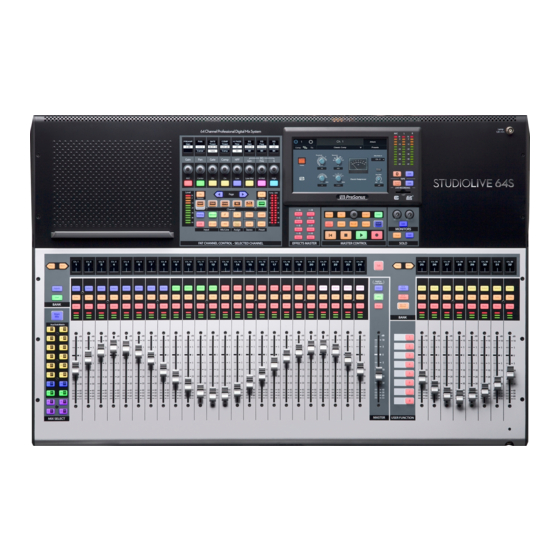
Hookup StudioLive™ Series III Rear Panel Configurations Owner’s Manual Hookup Rear Panel Configurations StudioLive 64S 3.1.1 Analog Inputs Mic / Line Mic Only Aux Inputs Tape Inputs Talkback In 32 Combo 4 1/4” TRS 2 RCA 1 XLR (F) Analog Outputs Flex Mix Subgroup Main Out... -
Page 19: Rear Panel Configurations
Hookup StudioLive™ Series III Rear Panel Configurations Owner’s Manual StudioLive 32SX 3.1.3 Analog Inputs Mic / Line Mic Only Aux Inputs Tape Inputs Talkback In 16 Combo 16 XLR 4 1/4” TRS 2 RCA 1 XLR (F) Analog Outputs Flex Mix Subgroup Main Out Mono Sum... -
Page 20: Studiolive 32 (Blue Model)
StudioLive 16 (Blue Model) DESIGNED AND ENGINEERED IN BATON ROUGE, LA, USA • MANUFACTURED IN CHINA • PATENTS PENDING • “STUDIOLIVE” and “PreSonus” ARE REGISTERED TRADEMARSK OF PRESONUS AUDIO ELECTRONICS • SD LOGO IS A TRADEMARK OF SD-3C, LLC MANUFACTURING DATE... -
Page 21: Rear Panel Connections
3.2.1 Mic/Line Inputs. Each microphone input on the StudioLive Series III mixers is supplied with a remote PreSonus XMAX microphone preamplifier, for use with all types of microphones. The XMAX preamp features a Class A input buffer circuit, followed by a dual-servo gain stage. This results in exceptionally low noise, and a wide range of gain, allowing you to boost signals significantly without introducing unwanted background noise. -
Page 22: Analog Outputs
Hookup StudioLive™ Series III Rear Panel Connections Owner’s Manual Talkback Mic Input. StudioLive mixers do not have a built-in talkback microphone, rather they are equipped with an additional XMAX mic preamp to connect an external microphone for talkback use. Note: Phantom power is always enabled on the Talkback Mic input. If using a dynamic mic, we recommend checking its documentation to verify that phantom power will not harm it. -
Page 23: Digital And Networking
Hookup StudioLive™ Series III Rear Panel Connections Owner’s Manual Main / Mono level controls (32-channel models). All 32-channel StudioLive mixer models are equipped with a level control to adjust the output level at the analog stage. The Main (stereo) output attenuation control has a range of -80 to 0 dB. The Mono output level control has a range of -80 to +6 dB. -
Page 24: Power
Hookup StudioLive™ Series III Top Panel Connections Owner’s Manual 3.2.4 Power Power Input. Connect the provided IEC power cable to this input. Power Switch. Push the top part of this switch to power your StudioLive on, and the bottom to switch power off. Power User Tip: StudioLive Series III mixers provide a Soft Power Down option from the Home menu. -
Page 25: Typical Band Setup Diagrams
StudioLive™ Series III Hookup Owner’s Manual Typical Band Setup Diagrams Typical Band Setup Diagrams backup acoustic vocal mic lead vocal guitar/DI drum kit electric guitar amp bass/DI backup vocal mics keyboard/DI wireless in-ear (keys) wireless router subwoofer front of house drum monitor sidefill speakers... -
Page 26: Typical Church Setup Diagrams
StudioLive™ Series III Hookup Owner’s Manual Typical Church Setup Diagrams Typical Church Setup Diagrams acoustic guitar/DI electric guitar electric guitar bass/DI drum kit StudioLive control surface amp (rhythm) amp (lead) piano iPads running Mobile devices UC Surface running QMix-UC wireless router keyboard/DI laptop running Capture... -
Page 27: Basic Mix Functions Overview
Basic Mix Functions Overview StudioLive™ Series III Channel Strip Basics Owner’s Manual Basic Mix Functions Overview StudioLive Series III mixers offer many powerful and flexible mixing tools that allow you to quickly set up and monitor multiple mixes at once and have been designed to make managing multiple layers of input channels, mix masters, and fader mixes, as well as navigating even the most complicated systems simple. -
Page 28: Fader Layers And Banks
Basic Mix Functions Overview StudioLive™ Series III Fader Layers and Banks Owner’s Manual Level Meter Each channel has a three-segment LED level meter, to provide an indication of the signal level. The bottom segment illuminates when the signal reaches -40 dBFS. The middle segment illuminates when the signal reaches -18 dBFS. -
Page 29: User Fader Layer
Basic Mix Functions Overview StudioLive™ Series III Fader Layers and Banks Owner’s Manual Mix/FX Masters. When enabled, the master level for Subgroups, FlexMixes, and FX buses are available from your StudioLive control surface as follows: • StudioLive 64S, StudioLive 32S, StudioLive 32SX, StudioLive 32, and StudioLive 24. -
Page 30: Filter Dca Groups
Basic Mix Functions Overview StudioLive™ Series III Filter DCA Groups Owner’s Manual To Edit the User layer, press and hold the Select button for the channel for which you’d like to change the assignment. This will open the User Layer Assignment screen. -
Page 31: Editing Or Deleting A Filter Dca Group
Basic Mix Functions Overview StudioLive™ Series III Filter DCA Groups Owner’s Manual 4. Press the “Edit” button on the Master Control Touch Display. 5. Press the default name to create custom filter name. Press “Enter” when done. Main Volume -84.00 dB Edit Auto Groups Traditional DCA... -
Page 32: Dca Group Options
Basic Mix Functions Overview StudioLive™ Series III Main Meters Owner’s Manual DCA Group Options 4.3.4 From the DCA Groups page, you have two options to customize the way these groups function on your mixer: Your StudioLive will automatically create a DCA group for channels that are tagged in the same category (i.e., Drums, Horns, etc.), this button allows you to toggle that option on or off. -
Page 33: Talkback Edit Screen
Basic Mix Functions Overview StudioLive™ Series III Talkback System Owner’s Manual Talkback Edit Screen 4.5.1 Press the Talkback Channel’s Select button to open the Talkback Edit screen, giving you access to additional options. • Preamp Gain. Sets the preamp gain for the Talkback mic input. •... -
Page 34: Buses And Routing
Buses and Routing StudioLive™ Series III FlexMixes Owner’s Manual Buses and Routing StudioLive Series III mixers were designed to be highly adaptive to your mix environment. At the core of this design philosophy are the FlexMixes, however, dedicated Internal FX buses, four fixed subgroups (32-channel models), and a main mono bus (StudioLive 64S) round out the complement of routable outputs on your StudioLive mixer. -
Page 35: Aux Mixes
Buses and Routing StudioLive™ Series III Aux Mixes Owner’s Manual To select the type of FlexMix functionality (Aux, Subgroup, or Matrix), touch the gear-shaped button to open the FlexMix Settings screen and make your selection from the menu. Once you’re done, exit the FlexMix Settings screen and create your mix. -
Page 36: Pre/Post Channel Sends
Buses and Routing StudioLive™ Series III Aux Mixes Owner’s Manual Press the Settings button on the Master Control Touch Display. Press the Aux button under FlexMix Mode. 5.2.1 Pre/Post Channel Sends You can select the send positions for the channels routed to each Aux mix. By default, all aux buses are set to Pre 1. -
Page 37: Working With External Effects Processors
Buses and Routing StudioLive™ Series III Aux Mixes Owner’s Manual Move the Master fader to adjust the overall level of the monitor mix. BANK 5. You can listen to the monitor mix you’re creating in your headphones or control room monitors by pressing the Edit button in the Monitors control section. -
Page 38: Subgroups
Buses and Routing StudioLive™ Series III Subgroups Owner’s Manual Press the Next button to bring the Aux Input channel layer. Press the Select button that corresponds to Aux Input 1 (the input pair you’re using as an effects return), to access its settings in the Fat Channel. Press the LR (StudioLive 64S) or Main button in the Fat Channel to assign Aux Input 1 to the main output mix. -
Page 39: Creating A Subgroup
Buses and Routing StudioLive™ Series III Subgroups Owner’s Manual Creating a Subgroup 5.3.1 Press the Select button for the FlexMix Master you’d like to make a Subgroup. Talk Hold to Lock Main Inputs Groups Mix/FX Master BANK Press the Settings button on the Master Control Touch Display. Press the Subgroup button under FlexMix Mode. -
Page 40: Creating Instrument Subgroups
Buses and Routing StudioLive™ Series III Subgroups Owner’s Manual To add a channel to a fixed Subgroup: Select the channel and press the Subgroup button in the Assign section of Level Comp Page the Fat Channel. This will bring up the Assigns menu on the Touch Display. Processor EQ / Dyn (Insert) - Page 41 Buses and Routing StudioLive™ Series III Subgroups Owner’s Manual Enable all four Stereo Link Options. In the Fat Channel, press the Stereo Link button. Ch. 10 Ch. 11 Ch. 12 Ch. 13 Ch. 14 Ch. 15 Ch. 13 Select Select Select Select Select...
-
Page 42: Matrix Mixes
Buses and Routing StudioLive™ Series III Matrix Mixes Owner’s Manual Press the FlexMix fader’s Select button to use the Fat Channel section to add dynamics processing and EQ to the stereo drum group. Talk Hold to Lock Main Inputs Groups Mix/FX Master BANK... -
Page 43: Creating A Front Fill Mix
Buses and Routing StudioLive™ Series III FX Buses Owner’s Manual Pre/Post Channel Sends You can select the send positions for the channels routed to each Matrix mix. By default, all Matrix mixes are set to Pre 1. This places the send of every input channel to each aux bus before the fader, limiter, EQ, and compressor, but after the Polarity Invert switch, high-pass filter, and gate. -
Page 44: Creating Internal Bus Fx Mixes
Buses and Routing StudioLive™ Series III Main Mono/Center Bus (StudioLive 64S only) Owner’s Manual Creating Internal Bus FX Mixes 5.5.1 There are at least two main advantages to creating an effects mix instead of inserting an effect on a channel. First, several channels can be sent to a single processor. In addition to greatly simplifying the number of parameters you have to control, this can help to create a cohesive sound for your mix. -
Page 45: Mono Bus Mode
Buses and Routing StudioLive™ Series III Main Mono/Center Bus (StudioLive 64S only) Owner’s Manual From this menu, you can toggle between Stereo Pan Mode and LCR Pan mode. Sample Rate: Permissions 48 kHz Network Clock: Regardless of mode, the Mono/Center output level is always grouped to the Main Internal Pan Mode: Show Peak Hold:... -
Page 46: Lcr Mode
Buses and Routing StudioLive™ Series III Main Mono/Center Bus (StudioLive 64S only) Owner’s Manual But what if you want more kick in your subwoofer? Or less keys? This is where the Mono send comes into play, allowing you to customize your low- frequency mix to better enhance your system. - Page 47 Buses and Routing StudioLive™ Series III Main Mono/Center Bus (StudioLive 64S only) Owner’s Manual When the Center Divergence control is set to 100% and the channel is panned to center (<C>), the entire signal will be sent to the Center bus and none will be sent to the Left or Right sides of the Main stereo bus: Mono Channel Stereo Channel (Left)
-
Page 48: The Fat Channel
The Fat Channel StudioLive™ Series III Overview Owner’s Manual The Fat Channel Overview The Fat Channel gives you powerful signal processing, mixing, and configuration tools for each channel and bus on your StudioLive. To begin working on a channel or mix with the Fat Channel, simply press its Select button. -
Page 49: A/B Comparison For Eq And Dynamics Settings
The Fat Channel StudioLive™ Series III Overview Owner’s Manual Input Channels Aux & Tape Inputs FX Returns FlexMixes Main Mix √ Preamp Gain Hi Pass Filter √ √ √ Gate √ √ √ √ √ √ Compressor 4-Band 4-Band 4-Band 6-Band 6-Band Limiter... - Page 50 The Fat Channel StudioLive™ Series III Overview Owner’s Manual The Save and Load buttons let you save and load Fat Channel presets, letting you store and reapply useful Fat Channel processing and utility settings to future mixes. While all Fat Channel settings are included when you save a preset, you can choose to filter out some types of settings, to load only part of a preset (such as only EQ and compressor parameters).
-
Page 51: Fat Channel Navigation
The Fat Channel StudioLive™ Series III Fat Channel Navigation Owner’s Manual Select a preset and load it by pressing the Recall button in the Master Control area. Talk You can also momentarily audition the effects of a preset by selecting a preset Select Select Select... - Page 52 The Fat Channel StudioLive™ Series III Fat Channel Navigation Owner’s Manual Fixed Fat Channel The eight encoders and buttons on the StudioLive 32SX and StudioLive 32SC always control the following functions: 9 10 11 12 13 14 15 16 1. AGC (Automatic Gain Compensation). 2.
-
Page 53: Input Mode
The Fat Channel StudioLive™ Series III Input Mode Owner’s Manual 1. Processor On/Off. Enables/Disables the currently active processor. 2. Input. For all StudioLive models, this opens the Channel Overview screen on the Touch Display. For models equipped with a Dynamic Fat Channel, this button will spill the Input layer controls onto the Fat Channel displays, encoders, and buttons. - Page 54 The Fat Channel StudioLive™ Series III Input Mode Owner’s Manual 2. Pan. Use the encoder to set the currently selected channel or subgroup’s pan position across the stereo field. The pan position will be displayed on the Scribble Strip. Press the button below the encoder to reset the pan position to Center.
-
Page 55: Gate Mode (Dynamic Fat Channel)
More information about Gates and Expanders can be found at: www.presonus.com/learn/technical-articles/How-To-Use-Dynamics- Processing-Getting-Started-With-Compressors-Gates-and-More Dynamic Fat Channel Controls 6.4.1... -
Page 56: Compressor Mode (Dynamic Fat Channel)
The Fat Channel StudioLive™ Series III Compressor Mode (Dynamic Fat Channel) Owner’s Manual 6. Key Filter. This encoder sets, and the scribble displays, the frequency at which the gate will open. Setting a specific frequency, in addition to a specific decibel level, provides more sonic shaping. -
Page 57: Tube Leveling Amplifier
The Fat Channel StudioLive™ Series III Compressor Mode (Dynamic Fat Channel) Owner’s Manual compressed, or “squashed, ” sound. All ranges of release can be useful, however, and you should experiment to become familiar with different sonic possibilities. 5. Gain. Sets the amount of “makeup gain” to apply to a signal. Once a signal is compressed, its overall level is often reduced. -
Page 58: Class-A Fet Compressor
The Fat Channel StudioLive™ Series III Compressor Mode (Dynamic Fat Channel) Owner’s Manual 6.5.3 Class-A FET Compressor Dynamic Fat Channel Controls When the Class-A FET Compressor is selected, the following controls are available in the Fat Channel: Input Output Attack Release Ratio Key Fltr... -
Page 59: Eq Mode (Dynamic Fat Channel)
The Fat Channel StudioLive™ Series III EQ Mode (Dynamic Fat Channel) Owner’s Manual EQ Mode (Dynamic Fat Channel) Pressing the EQ button in the Fat Channel gives you access to equalization settings for the currently selected channel or mix. An EQ (or equalizer) is a tone control that lets you make changes in the tonal balance of a signal. -
Page 60: Passive Program Eq
The Fat Channel StudioLive™ Series III EQ Mode (Dynamic Fat Channel) Owner’s Manual When a bus is selected, the EQ has six bands. Use the Page navigation buttons to navigate between Bands 1-4 and Bands 5-6. Press the Processor button to turn the EQ on or off. 6.6.2 Passive Program EQ Dynamic Fat Channel Controls... -
Page 61: Aux Sends Mode (Dynamic Fat Channel)
The Fat Channel StudioLive™ Series III Aux Sends Mode (Dynamic Fat Channel) Owner’s Manual 3. L-Mid Gain. Sets the amount of boost or cut to apply the low-mid-frequency band of this EQ. 4. L-Mid Frequency. Sets the center frequency of the low-mid-frequency band of this EQ. -
Page 62: Fat Channel Screens
The Fat Channel StudioLive™ Series III Fat Channel Screens Owner’s Manual Fat Channel Screens 6.8.1 Channel Overview While an Input channel is selected and Input mode is active, the Channel Overview is shown on the Touch Display: 1. Signal Source. Displays whether this channel is receiving signal from an analog or digital source. -
Page 63: Channel Settings Screen
The Fat Channel StudioLive™ Series III Fat Channel Screens Owner’s Manual Channel Settings Screen 6.8.2 When the overview screen for a channel or bus is open, can access the Channel Settings screen by tapping on the Settings button (Call-out #3). 1. -
Page 64: Gate Overview Screen
The Fat Channel StudioLive™ Series III Fat Channel Screens Owner’s Manual Gate Overview Screen 6.8.3 While Gate is active in the Fat Channel, the Touch Display displays the Gate Overview screen, displaying every Gate parameter available, along with useful metering and a graphical representation of the effect of current settings. -
Page 65: Compressor Overview Screens
Included in the Classic Studio Bundle. • RC-500 Compressor. FET-based compressors such as the one in the PreSonus RC 500 use transistors to emulate a triode tube’s operation and sound. Modeled after PreSonus’... - Page 66 The Fat Channel StudioLive™ Series III Fat Channel Screens Owner’s Manual Power User Tip: Use the Shift or Tap buttons to “null” button any parameter by pressing and holding the Shift or Tap button while adjusting the control of your choice to return that control to its default setting.
- Page 67 The Fat Channel StudioLive™ Series III Fat Channel Screens Owner’s Manual 5. Gain. Sets Make-up Gain for the Compressor. 6. Release. Sets the Release time for the Compressor. 7. Input Meter. Displays the pre-Compressor signal level. 8. Graph. Displays current compression curve. 9.
-
Page 68: Eq Overview Screens
The Fat Channel StudioLive™ Series III Fat Channel Screens Owner’s Manual 6.8.4.3 Class-A FET Compressor Overview Screen When the Fat Channel is in Class A FET Compressor mode, the Touch Display shows an overview screen that displays the relevant parameters. Touching any onscreen knob allows you to use the Master Control encoder to set the selected parameter. - Page 69 • RC-500 EQ. It’s rare to find a truly outstanding solid-state channel strip that can deliver a vintage vibe reminiscent of classic high-end products, yet employs a thoroughly modern design. The PreSonus RC 500 was one of these rare gems. The RC 500 EQ plug-in is modeled after the channel strip’s 3-band semi-parametric EQ and combines isolated filters and optimized, per-band Q to provide subtle signal- shaping without harsh artifacts.
- Page 70 The Fat Channel StudioLive™ Series III Fat Channel Screens Owner’s Manual 1. Signal Source. Displays whether this channel is receiving signal from an analog or digital source. Press to open the Digital Patching screen. For more information, see Section 12.3.1. 2.
- Page 71 The Fat Channel StudioLive™ Series III Fat Channel Screens Owner’s Manual 5. Band 1 Select. Selects Band 1 for control via Gain (#1), Frequency (#2), and Q (#3). 6. Band 1 On/Off. Enables/disables Band 1. 7. Band 2 Select. Selects Band 2 for control via Gain (#1), Frequency (#2), and Q (#3).
- Page 72 The Fat Channel StudioLive™ Series III Fat Channel Screens Owner’s Manual 1. EQ On/Off. Enables/disables the EQ globally. Touch to toggle on or off 2. Low Boost. Boosts the Low Band. 3. Low Frequency. Sets the center frequency for the Low Band. 4.
-
Page 73: Aux Sends Overview Screen
The Fat Channel StudioLive™ Series III User Mode Owner’s Manual Aux Sends Overview Screen 6.8.6 While Aux Sends Mode is engaged, the Touch Display displays the Aux Sends Overview screen. This screen displays the send level of the Selected channel in every FlexMix: User Mode The User Mode allows you to create your own custom Fat Channel controls. -
Page 74: Input Meters
The Fat Channel StudioLive™ Series III 6.10 Input Controls Owner’s Manual By pressing and holding any of these buttons, you’ll enter Multi-Assign mode, which allows you to set the input source for multiple channels at once. Once in this mode, the Select button for every Input Channel will flash. - Page 75 The Fat Channel StudioLive™ Series III 6.10 Input Controls Owner’s Manual Network Input Source Press the Network Input Source icon to select the Network Input that will be active on the currently selected channel or bus when the source is set to Network in the Fat channel.
-
Page 76: Polarity And Phantom Power
The Fat Channel StudioLive™ Series III 6.10 Input Controls Owner’s Manual Polarity and Phantom Power 6.10.4 When an analog input channel is selected, these buttons let you toggle channel polarity flipping (Ø) and phantom power (+48V) on or off. Power User Tip: When recording with more than one open microphone, use the polarity invert to combat phase cancellation between microphones. -
Page 77: Output Assignment Buttons
The Fat Channel StudioLive™ Series III 6.11 Output Assignment Buttons Owner’s Manual Output Assignment Buttons 6.11 6.11.1 Main/Mono Bus Assignment (StudioLive 64S only) When an input channel is selected, you can use these buttons to assign it to the Main and Mono/Center buses. -
Page 78: Tape Controls
Tape Controls StudioLive™ Series III Pairing a Bluetooth Device Owner’s Manual Tape Controls By default, the Tape channel is sourced from the analog Tape In jacks on the rear of the mixer and the currently paired Bluetooth audio device simultaneously. The two signals are mixed together and summed on the Tape In channel. -
Page 79: Sd Recording
Please note: The StudioLive Series III mixers support both SD and SDHC cards up to 32 GB. Tested and approved models and brands can be found at www.PreSonus.com. The first time you insert your SD/SDHC card, you should perform a Speed Test. This... -
Page 80: Loading A Session For Playback
Section 9.6.2. Capture Screen PreSonus Capture is a multitrack digital-audio recording application designed to make recording with StudioLive mixers quick and easy. This application is built into StudioLive Series III mixers, allowing you to track directly to an SD card using the same high-quality audio engine as PreSonus’... -
Page 81: Recording Status Messages
SD Recording StudioLive™ Series III Capture Screen Owner’s Manual 1. Record Duration. Shows the total recorded length of the current Session. 2. Current Position. Shows the current position of the recording and playback. 3. Timeline. Shows the current cursor location in the timeline of the current Session. -
Page 82: Transport Controls
SD Recording StudioLive™ Series III Capture Screen Owner’s Manual • Preparing... The session currently processing an action. This is commonly seen when attempting to play back a long session after it is first loaded or has just finished recording. • Playing. The recorded session audio is currently being played back. Rec Errors: •... -
Page 83: Virtual Sound Check
SD Recording StudioLive™ Series III Virtual Sound Check Owner’s Manual Virtual Sound Check We’ve all been there. The drummer is stuck in traffic. The guitarist is stuck at work. And you’re stuck at front-of-house (FOH) with a hyped up lead singer and bass player and no way to dial in a front-of-house mix, let alone set up the singer’s in-ear mix. -
Page 84: Master Control
Master Control StudioLive™ Series III StudioLive Series III FLEX DSP Rack Effects Owner’s Manual Master Control The Master Control area contains an array of controls that give you access to vital functions of the mixer including the StudioLive Series III FX rack, UCNET communication, DAW control, and the scene library. -
Page 85: The Effects Editor
Master Control StudioLive™ Series III StudioLive Series III FLEX DSP Rack Effects Owner’s Manual If you have just one effects slot occupied by a delay effect, this button will set its tempo. If you have more than one delay effect active, you must choose which delay is governed by this button by pressing the Tap Assign button in the Effects Editor for the desired delay. - Page 86 Master Control StudioLive™ Series III StudioLive Series III FLEX DSP Rack Effects Owner’s Manual • Size. Sets the width of the stereo image. • LPF Frequency. Use this control to attenuate low frequencies that can muddy a reverb. • LF Damping Freq. Use this control with create a warmer sound. This will enhance content at the frequency you set.
- Page 87 Master Control StudioLive™ Series III StudioLive Series III FLEX DSP Rack Effects Owner’s Manual • LF Damp Freq. Use this control with create a warmer sound. This will enhance content at the frequency you set. • LF Damping Gain. Sets the level at which the damping frequency will be boosted.
- Page 88 Master Control StudioLive™ Series III StudioLive Series III FLEX DSP Rack Effects Owner’s Manual 9.1.2.6 Stereo Delay This delay effect is inspired by a classic 80’s-era dual-delay unit and provides the following controls: • Delay Time A and B. Sets the length of their respective delay line. •...
- Page 89 Master Control StudioLive™ Series III StudioLive Series III FLEX DSP Rack Effects Owner’s Manual 9.1.2.8 Chorus A chorus effect is created by mixing the source signal with one or more pitch-shifted copies of it and then modulating the copies using an LFO. •...
-
Page 90: Effects Presets
Master Control StudioLive™ Series III StudioLive Series III FLEX DSP Rack Effects Owner’s Manual Effects Presets 9.1.3 From the Effects Presets screen, you can load factory and custom presets for each Effect Type as well as store your own custom presets. To save an Effects Preset: Tap the desired location for your new preset. -
Page 91: Ucnet
UCNET Owner’s Manual UCNET UCNET is a special networking protocol that PreSonus created to enable advanced remote control and audio transmission features between various PreSonus hardware and software products. This includes devices running Studio One, Capture, UC Surface, and QMix-UC software. -
Page 92: Software Control
Master Control StudioLive™ Series III UCNET Owner’s Manual UC Surface Device Permissions When setting permissions for UC Surface, you can choose to filter out certain functions. When the button is the off state, the function will not be available for the selected device. -
Page 93: Control Network Ip Address
Master Control StudioLive™ Series III UCNET Owner’s Manual Control Network IP Address Settings 9.4.4 In the Control Network area of the UCNET screen, you’ll see the current IP address of your StudioLive. This IP address can be assigned in one of three ways. Select the necessary IP assignment mode by touching one of the following buttons: •... -
Page 94: Daw Button
Master Control StudioLive™ Series III DAW Button Owner’s Manual DAW Button Your StudioLive can act as a control surface for the mixer functions of a computer running our Studio One, Logic or ProTools software. Press the DAW button to switch between normal mixing functions and DAW control. -
Page 95: Creating And Recalling Scenes
Master Control StudioLive™ Series III Scenes and Projects Owner’s Manual Saving a Project 1. To save a project, press the Scenes button. Talk Prev Select Select Select Select Select Select Inputs 2. Tap the desired location for your new Project. You can select an Empty Solo Solo Solo... - Page 96 Master Control StudioLive™ Series III Scenes and Projects Owner’s Manual Saving a Scene 1. To save a scene, press the Scenes button. Talk Prev Select Select Select Select Select Select Inputs This will open the Scenes library menu on the Touch Display. The Store and Solo Solo Solo...
-
Page 97: Filters
Master Control StudioLive™ Series III Scenes and Projects Owner’s Manual Filters 9.6.3 At the top of the Project and Scenes library screen, you will find the Filters button. Tapping this will open the Filters screen. From here you can select the parameters you want to be affected when you recall a Project or a Scene. - Page 98 Master Control StudioLive™ Series III Scenes and Projects Owner’s Manual Scene Filters Filter Name Included Parameters Name Channel Info Color Type Fat Channel Settings for all Inputs: High Pass Filter Gate Settings and Key Source Input Fat Channel Compressor Settings and Key Source EQ Settings Fat Channel Order (EQ<>Comp) Limiter Setting...
-
Page 99: List Editor
Master Control StudioLive™ Series III Scenes and Projects Owner’s Manual List Editor 9.6.4 The List Editor allows you to change Project and Scene names, delete them, lock the ability to make changes to them, as well as reorder your Scene library as necessary. Tapping on the List Editor tab opens the editor. -
Page 100: Scene Safe
Master Control StudioLive™ Series III Scenes and Projects Owner’s Manual Scene Safe 9.6.5 In some cases, you may want to protect a channel or bus from being affected when scenes are recalled. To do this, touch the Scene Safe button. This opens the Scene Safe screen on the Touch Display. -
Page 101: Reset
Master Control StudioLive™ Series III Scenes and Projects Owner’s Manual Reset 9.6.6 For both Projects and Scenes, you’ll find a Reset button. This button resets the currently loaded Project or Scene to the default state. Because you will potentially lose any changes to your current mix, you will be prompted to confirm this choice. Project Reset Inputs and Buses Mode... -
Page 102: Nulling Parameters
Master Control StudioLive™ Series III Scenes and Projects Owner’s Manual Their parameters will be set as follows: Fat Channel Parameters CHANNEL HIPASS NOISE GATE LIMIT COMPRESSOR L.MID H.MID HIGH GAIN STATE STATE THRESH 0 dB STATE <C> RANGE PEAK PEAK Source Analog 5 ms... -
Page 103: Monitoring Controls
Monitoring Controls StudioLive™ Series III 10.1 Solo Controls Owner’s Manual Monitoring Controls In addition to the main outputs, your StudioLive mixer features a set of monitor outputs and a headphone jack, each with its own distinct signal path. While you can use these outputs to listen to the main mix, you can also assign other signals to them, such as Aux mixes, the solo bus, or the tape input. -
Page 104: Solo Controls
Monitoring Controls StudioLive™ Series III 10.1 Solo Controls Owner’s Manual Solo Modes 10.1.1 To access the Solo bus controls, press the Edit button in the Solo control section. This will make the following controls available in the Touch Display. 1. Exit. Closes the Solo Edit screen. 2. -
Page 105: Using The Solo Bus For
Monitoring Controls StudioLive™ Series III 10.1 Solo Controls Owner’s Manual Using the Solo Bus for Monitoring 10.1.2 When mixing live, or when recording multiple musicians at once, it is often necessary to quickly listen to just one instrument or group. The Solo and Monitor buses can be used together for this purpose. -
Page 106: Using Solo In Place To
Monitoring Controls StudioLive™ Series III 10.1 Solo Controls Owner’s Manual Using Solo in Place to Set Up a Mix 10.1.3 We started this manual with a quick and easy way to set up the input levels for your StudioLive, ensuring that you have the highest possible input level without clipping your analog-to-digital converters. -
Page 107: Graphic Eq
Graphic EQ StudioLive™ Series III 10.1 Solo Controls Owner’s Manual Graphic EQ Your StudioLive comes packed with 31-band graphic EQ processors that can be freely assigned to the Main mix, or your choice of FlexMixes. These can be used for system tuning, subtle tweaks, or wherever you find them useful. -
Page 108: Assigning Geqs
Graphic EQ StudioLive™ Series III 11.1 Assigning GEQs Owner’s Manual Assigning GEQs 11.1 To assign a Graphic EQ to one of the mixes, select the desired mix and press the GEQ button. This will open the GEQ screen. Touching a mix will insert a Graphic EQ on it post-fader. -
Page 109: Geq Presets
Graphic EQ StudioLive™ Series III 11.3 GEQ Presets Owner’s Manual GEQ Presets 11.3 To store or load a GEQ preset for the currently selected instance, touch the Presets button while the GEQ screen is active. This loads the GEQ Presets screen. In this screen, to load a preset, scroll through the list of existing presets, and touch the preset of your choice to select it. - Page 110 Graphic EQ StudioLive™ Series III 11.4 Using the RTA to Ring Out Monitors Owner’s Manual 5. Feedback will show up as a line peak on the RTA. 6. Lower the GEQ gain control for the offending frequency in 3 dB increments to attenuate it out of your stage monitor.
-
Page 111: Home
Home StudioLive™ Series III 11.4 Using the RTA to Ring Out Monitors Owner’s Manual Home When you press the Home button, the Home screen opens on the Touch Display. This screen gives you access to settings and functions related to system configuration and troubleshooting. -
Page 112: System Screen
Home StudioLive™ Series III 12.1 System Screen Owner’s Manual System Screen 12.1 The System screen gives you access to many useful settings and functions that let you choose how your StudioLive looks and operates. The following functions are available: 1. Sample Rate. Sets the mixer’s sample rate. StudioLive Series III mixers can operate at 48 kHz or 44.1 kHz. -
Page 113: Permissions
Home StudioLive™ Series III 12.1 System Screen Owner’s Manual Permissions 12.1.1 Controlling your StudioLive remotely with UC Surface or QMix-UC for mobile devices allows you to move about the venue freely. However, it can also put the full power of the your mixer in multiple hands— some more adept than others. Therefore, your StudioLive enables you to limit each wireless device’s access to the mixer features by setting permissions. -
Page 114: Fat Channel Load/Paste
Home StudioLive™ Series III 12.1 System Screen Owner’s Manual In this screen, you can choose the function to assign to the chosen button, in the following categories: • Mute Groups. Lets you create stored sets of mute settings that correspond with the current state of the mixer, recallable at the press of the chosen User Button. -
Page 115: Firmware Update
SD card or UC Surface. To update using an SD Card, log into your My PreSonus account and download the new firmware version. Save the firmware file to an SD card and insert the card into your StudioLive mixer. Touch Update to complete the firmware update, or press Cancel to cancel the update. -
Page 116: Default Administrator
Home StudioLive™ Series III 12.2 User Profiles Owner’s Manual Default Administrator 12.2.1 User Profiles must be activated on your mixer. By default, your mixer is logged into the Default Adminitrator profile. This profile has access to every setting and parameter on your mixer. Several customized settings can be added to the Default Administrator profile. -
Page 117: Creating A New Profile
Touch the Enter button when done. Touch Cancel to leave the name unchanged. Select an Avatar By default, the PreSonus logo is the avatar for every user. This can be changed by tapping the default avatar on the profile settings page. - Page 118 Home StudioLive™ Series III 12.2 User Profiles Owner’s Manual Default Project and Scene Just like for the Default Administrator profile, you can select a Project to be loaded when someone logs into their User Profile. This is especially useful for less experienced users.
-
Page 119: Edit User Permissions
Home StudioLive™ Series III 12.2 User Profiles Owner’s Manual Edit User Permissions 12.2.3 When a User Profile is set to “User, ” permissions can be granted for certain functions and denied for others. The following features are only accessible from Administrator Profiles and always locked out in every User Profile: •... -
Page 120: Audio Routing And The Digital Patching Screen
Pressing the Audio Routing button in the Home screen will give you access to audio routing options for networked audio devices, USB sources, SD card recordings, and special settings for networked PreSonus devices. • AVB Input Streams. Touch to route available network sources to your StudioLive mixer’s AVB Inputs. -
Page 121: Digital Patching: Input Source
Home StudioLive™ Series III 12.3 Audio Routing and the Digital Patching Screen Owner’s Manual 12.3.1 Digital Patching: Input Source Selecting the Input Source menu will allow you to patch any source to any channel. From the Assigned Source menu, select the type of source you would like routed to a channel: •... -
Page 122: Digital Patching: Avb Sends
Home StudioLive™ Series III 12.3 Audio Routing and the Digital Patching Screen Owner’s Manual Press the reset button to repatch the default routing. You can route any of the following mixes to physical mix outputs on your StudioLive mixer: • FlexMixes •... -
Page 123: Digital Patching: Usb Sends
Home StudioLive™ Series III 12.3 Audio Routing and the Digital Patching Screen Owner’s Manual Digital Patching: USB Sends 12.3.4 Selecting the USB Sends menu will allow you to patch any channel send or mix to any USB driver send. Select the USB driver send to which you’d like to route your audio first. -
Page 124: Digital Patching: Sd Card
Home StudioLive™ Series III 12.3 Audio Routing and the Digital Patching Screen Owner’s Manual Digital Patching: SD Card 12.3.5 StudioLive 64S users. Selecting the SD Card menu will allow you to patch any input or mix to any of the 34 SD Card recording inputs. Select the SD Card recording input to which you’d like to route your audio first. -
Page 125: Utilities
Home StudioLive™ Series III 12.4 Utilities Owner’s Manual Utilities 12.4 Your StudioLive is equipped with a variety of utilities that allow you to test the functionality of your mixer. Pressing the Utility button from the Home screen will open this menu. The following test modes are available: •... -
Page 126: Resources
Resources StudioLive™ Series III 13.1 Networking Overview Owner’s Manual Resources 13.1 Networking Overview Networking your StudioLive Series III mixer involves both hardware and software components. The entire installation and configuration procedure is given in this manual, but before beginning, you must download and install UC Surface touch- control software onto a macOS or Windows computer or an iPad, as described in the StudioLive Software Library Reference Manual. - Page 127 Resources StudioLive™ Series III 13.1 Networking Overview Owner’s Manual 1. Connect standard CAT5e or CAT6 Ethernet cables from your computer’s Ethernet port to an Ethernet router, and from the router to the Control port on the StudioLive’s rear panel. 2. Launch Universal Control on the computer (macOS or Windows) that is connected to the router.
-
Page 128: Stereo Microphone Placement
Resources StudioLive™ Series III 13.2 Stereo Microphone Placement Owner’s Manual Stereo Microphone Placement 13.2 The following are a few recording applications to help you get started with your StudioLive. These are by no means the only ways to record these instruments. Microphone selection and placement is an art. -
Page 129: Acoustic Guitar
Resources StudioLive™ Series III 13.2 Stereo Microphone Placement Owner’s Manual Acoustic Guitar 13.2.3 Point a small-diaphragm condenser microphone at the 12th fret, approximately 8 inches away. Point a large-diaphragm condenser microphone at the bridge of the guitar, approximately 12 inches from the guitar. Experiment with distances and microphone placement. -
Page 130: Drum Overheads (Xy Example)
Resources StudioLive™ Series III 13.2 Stereo Microphone Placement Owner’s Manual Drum Overheads (XY example) 13.2.5 Place two small-diaphragm condenser microphones on an XY stereo-microphone holder (bar). Position the microphones so that each one is at a 45-degree angle, pointed down at the drum kit, approximately 7 or 8 feet above the floor or drum riser. -
Page 131: Compression Setting Suggestions
13.3 Compression Setting Suggestions Owner’s Manual Compression Setting Suggestions 13.3 The following are the compression presets that were used in the PreSonus BlueMax. We have included them as a jumping-off point for setting up compression on the StudioLive. 13.3.1 Vocals Soft. -
Page 132: Keyboards
Resources StudioLive™ Series III 13.3 Compression Setting Suggestions Owner’s Manual Keyboards 13.3.4 Piano. This is a special setting for an even level across the keyboard. It is designed to help even up the top and bottom of an acoustic piano. In other words, it helps the left hand to be heard along with the right hand. -
Page 133: Eq Frequency Guides
Resources StudioLive™ Series III 13.4 EQ Frequency Guides Owner’s Manual EQ Frequency Guides 13.4 13.4.1 What Frequencies to Cut and Boost Instrument What to Cut Why to Cut What to Boost Why to Boost Human Voice 7 kHz Sibilance 8 kHz Big sound 2 kHz Shrill... -
Page 134: Instrument Ranges
Resources StudioLive™ Series III 13.5 EQ Setting Suggestions Owner’s Manual Instrument Ranges 13.4.2 BOOST • harder bass to low • vocal presence frequency • kick & tom attack instruments (kick, • tom, bass) more finger sound • on bass • guitar and snare brighten vocals, •... -
Page 135: Percussion
Resources StudioLive™ Series III 13.5 EQ Setting Suggestions Owner’s Manual Pop Male Vocals LOW ON/OFF LOW SHELF LOW FREQ (Hz) LOW Q LOW GAIN LOW MID LOW MID LOW MID Q LOW MID GAIN ON/OFF FREQ (Hz) HIGH MID ON/ HI MID FREQ HIGH MID Q HIGH MID GAIN... -
Page 136: Fretted Instruments
Resources StudioLive™ Series III 13.5 EQ Setting Suggestions Owner’s Manual Fretted Instruments 13.5.3 Electric Bass LOW ON/OFF LOW SHELF LOW FREQ (Hz) LOW Q LOW GAIN LOW MID LOW MID LOW MID Q LOW MID GAIN ON/OFF FREQ (Hz) HIGH MID ON/ HI MID FREQ HIGH MID Q HIGH MID GAIN... -
Page 137: Using Input Delay
Resources StudioLive™ Series III 13.6 Using Input Delay Owner’s Manual Using Input Delay 13.6 When one of the input channels is selected, you can set an input delay up to 85 ms in 0.1 ms increments. An input delay has many uses. On small stages where the guitar amp and the kick and snare mics can be clearly heard in the vocal mic, an input delay can “move up”... -
Page 138: Aligning Direct And Mic'd Signals
Resources StudioLive™ Series III 13.6 Using Input Delay Owner’s Manual Press the guitar channel’s Select button. Press the Input button in the Fat Channel. Press the Next Page button in the Fat Channel to move to the second page Ch. 6 Ch. -
Page 139: Using Output Delay
Resources StudioLive™ Series III 13.7 Using Output Delay Owner’s Manual Press the Input Button in the Fat Channel. Increase the delay time on the Direct Input channel. This is the easiest way to hear the change in phase between the two signals. Listen to both till you find a happy medium between the combined signals. -
Page 140: Delay Systems
Resources StudioLive™ Series III 13.7 Using Output Delay Owner’s Manual 13.7.2 Delay Systems In most situations, a PA system relies on a main speaker system, positioned at the front of the room, to reproduce audio for the entire performance space. As a result, the level of the system is considerably louder at the front of the room then it is at the mix position. -
Page 141: Aligning Subs To Mains
Resources StudioLive™ Series III 13.7 Using Output Delay Owner’s Manual Mains delayed Front Fill delayed to backline to Mains It should be noted that frequencies in the sub-bass range of a delay system do not require distribution. In fact, a delay system’s high pass filter should be rolled up as high as 300 to 400 Hz to avoid sound going back toward the stage as low frequencies become omnidirectional. -
Page 142: Sidechaining
Resources StudioLive™ Series III 13.8 Sidechaining Owner’s Manual 13.8 Sidechaining Both the Compressor and the Gate on the Input channels can be triggered from another channel. Sidechaining has many uses. This section will explain how sidechaining can help to solve many common mixing problems. Sidechaining the Gate 13.8.1 As previously mentioned, the Gate’s key filter can be sidechained to another channel. -
Page 143: Sidechaining The Compressor
Resources StudioLive™ Series III 13.9 Effect Types Owner’s Manual Sidechaining the Compressor 13.8.2 Sidechaining a compressor allows you to reduce the level of one input source to make room for another. This is especially useful in live broadcast or application where music and commentary are happening simultaneously. -
Page 144: Delay And Its Parameters
Resources StudioLive™ Series III 13.9 Effect Types Owner’s Manual Early Reflections. Early reflections are those that reach the listener a few milliseconds after the direct signal arrives. Your brain uses them to identify the size of the room you’re in. If you are trying to simulate a specific type of room, this control will be extremely important. -
Page 145: 13.10 Using The Rta While Mixing
Resources StudioLive™ Series III 13.10 Using the RTA While Mixing Owner’s Manual Below are some of the most common parameters for the flanger and chorus effects: • Rate. Sets the frequency of the LFO modulating the delayed signal. • Width. Shifts the phase of the LFO modulating the delayed signal. •... -
Page 146: Technical Information
Technical Information StudioLive™ Series III 14.1 Specifications Owner’s Manual Technical Information 14.1 Specifications Microphone Preamplifier Input Type XLR Female, balanced Frequency Response to Main Output (at unity gain) 20-20 kHz, ±0.5 dBu Input Impedance 1 kΩ THD to Main Output <0.005%, +4 dBu, 20-20 kHz, unity gain, unwtd S/N Ratio to Main Output (Ref = +4 dB, 20 kHz BW, unity gain, A-wtd) 94 dB... - Page 147 Technical Information StudioLive™ Series III 14.1 Specifications Owner’s Manual System Crosstalk Input to Output -90 dB (Ref = +4 dBu, 20 Hz-20 kHz, unwtd) Adjacent Channels -87 dB (Ref = +4 dBu, 20 Hz-20 kHz, unwtd) Digital Audio and Control ADC Dynamic Range 115 dB (A-wtd, 48 kHz) DAC Dynamic Range...
-
Page 148: Default Routing
Technical Information StudioLive™ Series III 14.2 Default Routing Owner’s Manual Default Routing 14.2 14.2.1 Input Source Input StudioLive 64S StudioLive 32S StudioLive 32SX StudioLive 32SC StudioLive 32 StudioLive 24 StudioLIve 16 Channel 1 Analog 1 Analog 1 Analog 1 Analog 1 Analog 1 Analog 1 Analog 1... - Page 149 Technical Information StudioLive™ Series III 14.2 Default Routing Owner’s Manual Input StudioLive 64S StudioLive 32S StudioLive 32SX StudioLive 32SC StudioLive 32 StudioLive 24 StudioLIve 16 (continued) (continued) (continued) (continued) (continued) (continued) (continued) (continued) Channel 45 AVB 45 Channel 46 AVB 46 Channel 47 AVB 47 Channel 48...
-
Page 150: Analog Sends
Technical Information StudioLive™ Series III 14.2 Default Routing Owner’s Manual Input StudioLive 64S StudioLive 32S StudioLive 32SX StudioLive 32SC StudioLive 32 StudioLive 24 StudioLIve 16 (continued) (continued) (continued) (continued) (continued) (continued) (continued) (continued) FlexMix 16 FlexMix 16 FlexMix 16 FlexMix 17 FlexMix 17 FlexMix 18 FlexMix 18... -
Page 151: Avb Sends
Technical Information StudioLive™ Series III 14.2 Default Routing Owner’s Manual AVB Sends 14.2.3 AVB Send StudioLive 64S StudioLive 32S StudioLive 32SX StudioLive 32SC StudioLive 32 StudioLive 24 StudioLIve 16 AVB Send 1 Channel 1 Channel 1 Channel 1 Channel 1 Channel 1 Channel 1 Channel 1... -
Page 152: Usb Sends
Technical Information StudioLive™ Series III 14.2 Default Routing Owner’s Manual AVB Send StudioLive 64S StudioLive 32S StudioLive 32SX StudioLive 32SC StudioLive 32 StudioLive 24 StudioLIve 16 (continued) (continued) (continued) (continued) (continued) (continued) (continued) (continued) AVB Send 45 Channel 45 Mix 5 Mix 5 Mix 5 Mix 5... - Page 153 Technical Information StudioLive™ Series III 14.2 Default Routing Owner’s Manual USB Send StudioLive 64S StudioLive 32S StudioLive 32SX StudioLive 32SC StudioLive 32 StudioLive 24 StudioLIve 16 (continued) (continued) (continued) (continued) (continued) (continued) (continued) (continued) USB Send 24 Channel 24 Channel 24 Channel 24 Channel 24 Channel 24...
-
Page 154: Sd Card
Technical Information StudioLive™ Series III 14.2 Default Routing Owner’s Manual SD Card 14.2.5 SD Card Send StudioLive 64S StudioLive 32S StudioLive 32SX StudioLive 32SC StudioLive 32 StudioLive 24 StudioLIve 16 SD Track 1 Channel 1 Ch. 1 (Fixed) Ch. 1 (Fixed) Ch. -
Page 155: Block Diagrams
Troubleshooting Information Please check the PreSonus Web site (www.presonus.com) regularly for software information and updates, firmware updates, and support documentation, including frequently asked questions. Online technical support is available to registered users through your My PreSonus account. Visit my.presonus.com to register. - Page 156 Integration, and XMAX are trademarks or registered trademarks of PreSonus Audio Electronics, Inc. Capture, Impact, Mixverb Presence, RedLightDist, SampleOne, Studio One, and Tricomp are trademarks or registered trademarks of PreSonus Software Ltd. Mac and macOS are registered trademarks of Apple, Inc., in the U.S. and other countries. Windows is a registered trademark of Microsoft, Inc., in the U.S.
- Page 157 StudioLive Series III ™ Digital Mix Console / Recorder with Motorized Faders Owner’s Manual 18011 Grand Bay Ct. • Baton Rouge, ® Louisiana 70809 USA• 1-225-216-7887 Part# 70-22000045-F www.presonus.com...