PRESONUS studiolive III series Owner's Manual
Digital mix console / recorder with motorized fades
Hide thumbs
Also See for studiolive III series:
- Owner's manual (232 pages) ,
- Quick start manual (20 pages) ,
- Networking manual (17 pages)

Related Manuals for PRESONUS studiolive III series


Summary of Contents for PRESONUS studiolive III series
- Page 1 StudioLive Series III ™ Digital Mix Console / Recorder with Motorized Faders Owner’s Manual ® English www.presonus.com...
-
Page 2: Table Of Contents
FX Buses — 30 Table of Contents 4.7.1 Creating Internal Bus FX Mixes — 30 Overview — 1 Fixed Subgroups — 30 Introduction — 1 Talkback System — 31 About this Manual — 1 Talkback Edit Screen — 31 4.9.1 Feature Summary —... - Page 3 13.6 How Long This Warranty Lasts — 109 10.2 GEQ Presets — 85 13.7 What PreSonus Will Do — 109 10.3 Using the RTA to Ring Out Monitors — 86 13.8 How to Get Warranty Service (USA) — 109 Resources — 87 13.9...
-
Page 5: Overview
Owner’s Manual Overview Introduction Thank you for purchasing your PreSonus® StudioLive™ Series III Digital Mixer. PreSonus Audio Electronics has built your StudioLive mixer with high-grade components to ensure optimum performance for many years to come. Loaded with 32 or 16 high-headroom XMAX™ microphone preamplifiers, a built-in 38x38 USB... -
Page 6: Feature Summary
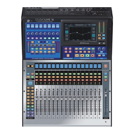
Overview StudioLive™ Series III Feature Summary Owner’s Manual Feature Summary General Controls • 33/17 touch-sensitive, motorized faders • RGB Select buttons with user-assignable colors • Transport control • All-new Fat Channel controls including: - 8 scribble strips, encoders, and multicolor buttons - Customizable user layer - 7-inch color touchscreen Inputs and Outputs... -
Page 7: What's In The Box
• IEC power cord Power User Tip: All companion software and drivers for your PreSonus StudioLive Series III mixer are available for download from your My PreSonus user account. Please visit http://my.presonus.com and register your StudioLive Series III mixer to receive downloads... -
Page 8: Getting Started
Getting Started StudioLive™ Series III Level Setting Procedure Owner’s Manual Getting Started Before you begin, here are a few rules to get you started: • Always turn down the Main fader and both the Monitor and Phones knobs in the Monitor section before making connections. - Page 9 Getting Started StudioLive™ Series III Level Setting Procedure Owner’s Manual Plug your StudioLive into a power outlet and turn it on. Move all of the faders on your StudioLive down to the lowest setting. Press the Select button on Channel 1 to bring it into focus in the Fat Channel.
-
Page 10: Level Setting Procedure
Getting Started StudioLive™ Series III Level Setting Procedure Owner’s Manual Press the Input button in the Fat Channel. 8. Turn the first knob in the Fat Channel section (Preamp Gain) counter- clockwise to its lowest setting. If your microphone requires phantom power, press the +48v button in the Fat Channel. - Page 11 Getting Started StudioLive™ Series III Level Setting Procedure Owner’s Manual 13. Raise the Channel 1 fader to its “U” setting (unity gain). 14. Press the “Main” button in the Fat Channel to assign Channel 1 to the Main output bus. 15.
-
Page 12: Useful Concepts
Getting Started StudioLive™ Series III Useful Concepts Owner’s Manual Useful Concepts This section covers some basic workflow concepts to help you to more quickly get acquainted with your StudioLive. Select Buttons and the Fat Channel 2.2.1 All around the StudioLive, you will see Select buttons. There is a Select button on each channel as well as the master fader. -
Page 13: Flexmixes
Getting Started StudioLive™ Series III Useful Concepts Owner’s Manual FlexMixes 2.2.2 In a traditional analog console, there are several different types of buses, each feeding a dedicated output. Your StudioLive mixer features 16/10 analog Mix outputs, each driven by a FlexMix bus. Why do we call them FlexMixes? Because each FlexMix can be configured as any one of four bus types: •... -
Page 14: Hookup
Hookup Rear Panel Connections Microphone Inputs. Your StudioLive Series III mixer is supplied with 32/16 PreSonus XMAX microphone preamplifiers, for use with all types of microphones. The XMAX preamp features a Class A input buffer circuit, followed by a dual-servo gain stage. - Page 15 Hookup StudioLive™ Series III Rear Panel Connections Owner’s Manual Aux Inputs. The StudioLive offers two balanced stereo auxiliary inputs. While these line inputs are generally used as effects returns, they can also be used for any line-level source (synthesizers, amp modelers, etc.). The left input of each pair is normalled to the right input, so if you are returning a mono signal to the mix, connect it to the left input, and the signal will be routed to both sides of the mix.
- Page 16 Hookup StudioLive™ Series III Rear Panel Connections Owner’s Manual Tape In/Out. These RCA input and output jacks can be used to connect a music player (MP3, CD, tape) or other consumer device to your system. The Tape inputs are an available input source within the mixer, while the Tape outputs mirror the output of the Main output pair.
-
Page 17: Top Panel Connections
Hookup StudioLive™ Series III Top Panel Connections Owner’s Manual Power Input. Connect the provided IEC power cable to this input. Power Switch. Push the top part of this switch to power your StudioLive on, and the bottom to switch power off. Top Panel Connections Lamp Connector. -
Page 18: Typical Band Setup Diagrams
StudioLive™ Series III Hookup Owner’s Manual Typical Band Setup Diagrams Typical Band Setup Diagrams acoustic lead vocal guitar/DI drum kit backup vocal mics electric guitar amp bass/DI backup vocal mics keyboard/DI wireless in-ear wireless in-ear (keys) (lead vocals) wireless router subwoofer front of house drum monitor... -
Page 19: Typical Church Setup Diagrams
StudioLive™ Series III Hookup Owner’s Manual Typical Church Setup Diagrams Typical Church Setup Diagrams acoustic guitar/DI drum kit electric guitar electric guitar bass/DI StudioLive control surface amp (rhythm) amp (lead) piano iPads running Mobile devices UC Surface running QMix-UC wireless router laptop running Capture keyboard/DI... -
Page 20: Basic Mixing And Routing
Basic Mixing and Routing StudioLive™ Series III Channel Strip Basics Owner’s Manual Basic Mixing and Routing StudioLive Series III mixers offer many powerful and flexible mixing tools that allow you to quickly set up and monitor multiple mixes at once and have been designed to make managing multiple layers of input channels, mix masters, and fader mixes, as well as navigating even the most complicated systems simple. -
Page 21: Fader Layers And Banks
Basic Mixing and Routing StudioLive™ Series III Fader Layers and Banks Owner’s Manual Level Meter Each channel has a three-segment LED level meter, which gives a quick indication of signal levels flowing through that input, mix, or bus. The bottom segment begins to light when the signal reaches -40 dBFS. -
Page 22: User Fader Layer
Basic Mixing and Routing StudioLive™ Series III User Fader Layer Owner’s Manual User Fader Layer The User layer lets you choose a hand-picked selection of channels that are visible when you press the User button. This can be useful to access crucial channels quickly, especially in mixes with high channel counts. -
Page 23: Filter Dca Groups
Basic Mixing and Routing StudioLive™ Series III Filter DCA Groups Owner’s Manual Filter DCA Groups Professional mixing consoles have addressed the problem of managing complex mixes with population groups that reduce the channels you’re viewing at one time and DCAs that control the overall level of a group of channels. We’ve combined the best aspects of these solutions with Filter DCAs. -
Page 24: Editing Or Deleting A Filter Dca
Basic Mixing and Routing StudioLive™ Series III Main Meters Owner’s Manual Editing or Deleting a Filter DCA Group 4.4.2 1. To edit or delete a Filter DCA Group, first touch its name to select it. 2. Touch the Edit button to enter the Filter DCA Group Edit screen. 3. -
Page 25: Aux Mixes
Basic Mixing and Routing StudioLive™ Series III FlexMixes Owner’s Manual When a mix is selected, the Master fader will control its output level. To view the master output level for every mix, press the Mix/FX Masters button. To choose the type of FlexMix behavior to be used for the Aux (Aux, Subgroup, or Matrix), touch the gear-shaped button to open the FlexMix Settings screen and make your selection from the menu. - Page 26 Basic Mixing and Routing StudioLive™ Series III FlexMixes Owner’s Manual To create an Aux Mix: Press the Mix/FX Master button. This will bring up the FlexMix Masters onto the channel strips. Press the Select button for the FlexMix Master you’d like to make an Aux Mix.
- Page 27 Basic Mixing and Routing StudioLive™ Series III FlexMixes Owner’s Manual 4.6.1.1 Creating Aux Mixes Creating custom monitor mixes is critical. If musicians can’t hear themselves or their bandmates, their performance will suffer. A monitor mix can be mono or stereo. Most often, an individual live monitor mix is mono and is sent to a floor-wedge or sidefill monitor (the obvious exception being in-ear monitor systems).
- Page 28 Basic Mixing and Routing StudioLive™ Series III FlexMixes Owner’s Manual 4.6.1.2 Working with External Effects Processors Creating a mix to send to an external effects processor is similar to creating an internal FX mix, only in this case, we route the mix signal to a mix output (Mix Output 7, in this example), and route the effected signal from the processor back to a stereo Aux input (Aux Input 1, in this example) on the mixer.
-
Page 29: Subgroups
Basic Mixing and Routing StudioLive™ Series III FlexMixes Owner’s Manual Press the Main button in the Fat Channel to assign Aux Input 1 to the main output mix. Press the Mix 7 button in the Mix Select section to access settings for Aux 7 (the Aux mix you’re using to send channels to the external processor). -
Page 30: Creating Instrument Subgroups
Basic Mixing and Routing StudioLive™ Series III FlexMixes Owner’s Manual Press the Select button for the FlexMix Master you’d like to make a Subgroup. Press the Settings button on the Master Control Touchscreen. Press the Subgroup button under FlexMix Mode. 4.6.2.1 Creating Instrument Subgroups Grouping individual instruments that create a section in your mix has obvious advantages: The entire group can be muted or soloed, brought up or down in a mix,... - Page 31 Basic Mixing and Routing StudioLive™ Series III FlexMixes Owner’s Manual In the Touch Screen, press the Settings gear. Press the Subgroup button under FlexMix Mode. Enable all four Stereo Link Options. In the Fat Channel, press the Stereo Link button. Assign the Subgroup to the Main bus by pressing the Main assign in the Fat Channel.
- Page 32 Basic Mixing and Routing StudioLive™ Series III FlexMixes Owner’s Manual Now that we’ve created a stereo subgroup, let’s make an instrument group: The first step is to get a good mix of the instruments you are grouping—in this case, the drums. Beginning with Channel 1 (Kick), raise the fader and, with the drummer’s assistance, set the input trim, EQ, and dynamics for each drum separately.
-
Page 33: Matrix Mixes
Basic Mixing and Routing StudioLive™ Series III FlexMixes Owner’s Manual Matrix Mixes 4.6.3 On the simplest level, a matrix mix is a mix of mixes. A matrix mix allows you to combine any bus on your StudioLive as well as input channels. Matrix mixes can be the Swiss Army knife to solve some of the most problematic audio routing issues. -
Page 34: Fx Buses
Basic Mixing and Routing StudioLive™ Series III FX Buses Owner’s Manual FX Buses FX Buses act just like Aux mixes, but rather than feeding an output, they feed one of the StudioLive’s internal effects processors. This allows you to customize the amount of a channel’s signal that is being effected. -
Page 35: Talkback System
Basic Mixing and Routing StudioLive™ Series III Talkback System Owner’s Manual To add a channel to a fixed Subgroup: Select the channel and press the Subgroup button in the Assign section of Level Comp Page the Fat Channel. This will bring up the Assigns menu on the Touchscreen. Processor EQ / Dyn (Insert) -
Page 36: The Fat Channel
The Fat Channel StudioLive™ Series III Talkback System Owner’s Manual The Fat Channel The Fat Channel gives you powerful signal processing, mixing, and configuration tools for each channel and bus on your StudioLive. To begin working on a channel or mix with the Fat Channel, simply press its Select button. -
Page 37: Fat Channel Navigation
The Fat Channel StudioLive™ Series III Fat Channel Navigation Owner’s Manual The Fat Channel provides differing types of processing and utility settings depending on what type of channel or mix is selected. The following is a quick reference of the available processors and utility settings for each type of signal that the Fat Channel can process. -
Page 38: Input Mode
The Fat Channel StudioLive™ Series III Fat Channel Navigation Owner’s Manual 1. Processor On/Off. Enables/Disables the currently active processor. 2. Input. Displays the Fat Channel overview for the currently selected channel or bus in the Fat Channel and on the Touch Screen. See Section 5.1.1. 3. - Page 39 The Fat Channel StudioLive™ Series III Fat Channel Navigation Owner’s Manual pass through unaffected. You can set the threshold from 0 to -84 dB. See Section 5.1.2 for more information on the Noise Gate and its parameters. 5. Compressor Threshold. This encoder sets, and the scribble strip displays, the compressor threshold for the selected channel or output bus.
- Page 40 The Fat Channel StudioLive™ Series III Fat Channel Navigation Owner’s Manual 12. Delay. Sets the amount of alignment delay applied to the input channel or bus. Touch to enable manipulation by the Master Control encoder. See Section 11.6 and 11.7 for more information. 13.
-
Page 41: Gate Mode
The Fat Channel StudioLive™ Series III Fat Channel Navigation Owner’s Manual - Comp./Limiter. Enable this option to link the compression & limiting detection behavior for linked channels or buses. With this option on, signals occurring either linked channel cause identical gain reduction behavior in both. - Page 42 The Fat Channel StudioLive™ Series III Fat Channel Navigation Owner’s Manual 4. Release. Sets the time it takes for the gate to “close” when a signal falls beneath the threshold. Power User Tip: Gate release times should typically be set so that the natural decay of the instrument or vocal being gated is not affected.
- Page 43 The Fat Channel StudioLive™ Series III Fat Channel Navigation Owner’s Manual 9. Key Listen. Touch to enable the Key Listen function. 10. Output Meter. Displays the post-Gate signal level. 11. Gain Reduction Meter. Displays the amount of Gain Reduction applied by the Gate to the channel.
-
Page 44: Compressor Mode
The Fat Channel StudioLive™ Series III Fat Channel Navigation Owner’s Manual Select the kick drum channel as the Key Source, either by turning Encoder 5 in the Fat Channel to select it, or by using the Key Source selector on the touchscreen. - Page 45 The Fat Channel StudioLive™ Series III Fat Channel Navigation Owner’s Manual 6. Comp>EQ. The Compressor and EQ can be reordered in the signal path. By default, the signal passes through the compressor before passing through through EQ. When reordered, the EQ is placed before the compressor in the signal path.
- Page 46 The Fat Channel StudioLive™ Series III Fat Channel Navigation Owner’s Manual Fat Channel), along with useful metering and a graphical representation of the effect of current settings. Touching any onscreen knob allows you to use the Master Control encoder to set the selected parameter. Touching a drop-down selector (such as Key Source) lets you select from a list of relevant choices.
- Page 47 The Fat Channel StudioLive™ Series III Fat Channel Navigation Owner’s Manual 4. Key Filter. This encoder sets, and the scribble displays, the frequency at which the Tube Leveling Amplifier will engage. It will still process the entire frequency range, but it is only engaged when the specified frequency is present. Press the button below to listen to the signal being used to trigger the compressor (including the effects of the high-pass filter, as set with the Key Filter control).
- Page 48 The Fat Channel StudioLive™ Series III Fat Channel Navigation Owner’s Manual 6. Key Filter. This encoder sets, and the scribble displays, the frequency at which the compressor will engage. The compressor will still process the entire frequency range, but it is only engaged when the specified frequency is present.
-
Page 49: Eq Mode
The Fat Channel StudioLive™ Series III Fat Channel Navigation Owner’s Manual EQ Mode 5.1.4 Pressing the EQ button in the Fat Channel gives you access to equalization settings for the currently selected channel or mix. An EQ (or equalizer) is a tone control that lets you make changes in the tonal balance of a signal. - Page 50 The Fat Channel StudioLive™ Series III Fat Channel Navigation Owner’s Manual 2. Band 1 / Low Frequency/Q. The encoder can control either frequency or Q for this band of EQ. Use the button below to toggle between the two. When in Frequency mode, it sets the center frequency at which signals are boosted or cut by this band of EQ.
- Page 51 The Fat Channel StudioLive™ Series III Fat Channel Navigation Owner’s Manual 3. Q. Sets the Q for the currently selected band (Call-out #5, 7, 9, or 11). 4. Input Meter. Displays the Input signal to the EQ. 5. Band 1 Select. Selects Band 1 for control via Gain (#1), Frequency (#2), and Q (#3).
- Page 52 The Fat Channel StudioLive™ Series III Fat Channel Navigation Owner’s Manual 4. High Boost. Sets the level of boost applied around the chosen high frequency. 5. High Bandwidth. Sets the Q (or width) of the effect of the high EQ band. 6.
- Page 53 The Fat Channel StudioLive™ Series III Fat Channel Navigation Owner’s Manual 6. Hi-Mid Frequency. Sets the center frequency of the high-mid-frequency band of this EQ. 7. High Gain. Sets the amount of boost or cut to apply the high-frequency band of this EQ.
-
Page 54: Aux Sends Mode
The Fat Channel StudioLive™ Series III Fat Channel Navigation Owner’s Manual For example, let’s say you are mixing a particularly edgy-sounding lead guitar that is competing with the male vocal and distracting from the overall good tone of the instrument. By using the RTA in the Fat Channel, you can quickly identify the offending frequency by looking for spikes in the RTA. -
Page 55: User Mode
The Fat Channel StudioLive™ Series III Fat Channel Meters Owner’s Manual User Mode 5.1.6 The User Mode allows you to create your own custom Fat Channel controls. To assign a function to an encoder and its adjacent button, press any unassigned button. This will open the User Mode edit screen: When you are done assigning function, press the Done button on the Touchscreen. -
Page 56: Input Source Selection
The Fat Channel StudioLive™ Series III Input Source Selection Owner’s Manual Input Source Selection When a channel is selected (rather than a bus or output), these four buttons give you a choice of input type to be routed to that channel. Choose from the following: •... -
Page 57: Settings
The Fat Channel StudioLive™ Series III A/B Comparison for EQ and Dynamics Settings Owner’s Manual You can assign a channel output to a subgroup in two different ways: Press the Subgroup button and release it, the Subgroup Assignment view shows in the touchscreen, with a list of all available subgroups. -
Page 58: Stereo Link
The Fat Channel StudioLive™ Series III Stereo Link Owner’s Manual Stereo Link When a channel or mix is selected, pressing this button links some of the parameters of a channel or mix with those of its even or odd counterpart (channel 1 links only with 2, 7 links with 8, and so on). - Page 59 The Fat Channel StudioLive™ Series III Copy/Paste & Preset Load/Save Owner’s Manual To save a preset: Press Save. The Fat Channel Presets view is shown on the touchscreen. Press the Store button in the Master Control area to bring up the onscreen keyboard.
- Page 60 The Fat Channel StudioLive™ Series III Copy/Paste & Preset Load/Save Owner’s Manual Select a preset and load it by pressing the Recall button in the Master Control area. You can also momentarily audition the effects of a preset by selecting a preset and pressing the Audition button on the touchscreen, or rename it by pressing Rename and entering a new name with the onscreen keyboard.
-
Page 61: Tape Controls
Tape Controls StudioLive™ Series III Pairing a Bluetooth Device Owner’s Manual Tape Controls By default, the Tape channel is sourced from the analog Tape In jacks on the rear of the mixer and the currently paired Bluetooth audio device simultaneously. The two signals are mixed together and summed on the Tape In channel. -
Page 62: Sd Recording
Please note: The StudioLive Series III mixers support both SD and SDHC cards up to 32 GB. Tested and approved models and brands can be found at www.PreSonus.com. The first time you insert your SD/SDHC card, you should perform a Speed Test. This... -
Page 63: Loading A Session For Playback
SD Recording StudioLive™ Series III Loading a Session for Playback Owner’s Manual When you’ve entered the artist name, performance name, or location for one Session, it is saved for easy use in future sessions (up to 10 of each category at a time). Saved designators can be easily selected by touching the drop-down menus in the right column of controls on this page. -
Page 64: Capture Screen
Owner’s Manual Capture Screen PreSonus Capture is a multitrack digital-audio recording application designed to make recording with StudioLive mixers quick and easy. This application is built into StudioLive Series III mixers, allowing you to track directly to an SD card using the same high-quality audio engine as PreSonus’... -
Page 65: Transport Controls
SD Recording StudioLive™ Series III Sound Check Button Owner’s Manual Transport Controls 7.3.1 When a new Session is created or an existing Session is loaded, the Transport buttons give you control over recording, playback, and navigation through the timeline of the current Session. -
Page 66: Master Control
Master Control StudioLive™ Series III Home Button Features Owner’s Manual Master Control The Master Control area contains the all-important touchscreen and an array of controls that give you access to vital functions of the mixer (such as FX, networking, DAW interactions, and so on). The following section details the use of these controls and the features they bring. -
Page 67: Home Button Features
Master Control StudioLive™ Series III Home Button Features Owner’s Manual System Screen 8.1.1 The System screen gives you access to many useful settings and functions that let you choose how your StudioLive looks and operates. The following functions are available: 1. - Page 68 Master Control StudioLive™ Series III Home Button Features Owner’s Manual QMix-UC Device Permissions When setting permissions for a device running QMix-UC software, the Mix selector gives you the following modes of control permission to choose from: • None. Select this to disable remote control on the selected device. •...
- Page 69 Master Control StudioLive™ Series III Home Button Features Owner’s Manual 8.1.1.2 User Buttons Assign (StudioLive 32 Only) The StudioLive 32 features eight user-assignable buttons. These buttons can control the following functions: Mute Groups 1-8, Tap Tempo A-D, Quick Scenes 1-8, Scene Navigation, or DAW Navigation.
- Page 70 Master Control StudioLive™ Series III Home Button Features Owner’s Manual In this screen, you can choose the function to assign to the chosen button, in the following categories: • Mute Groups. Lets you create stored sets of mute settings that correspond with the current state of the mixer, recallable at the press of the chosen User Button.
-
Page 71: Global Lockout
Master Control StudioLive™ Series III Home Button Features Owner’s Manual 8.1.1.4 Firmware Update From the System menu, you can check the current firmware version and check for firmware updates by pressing the Firmware button. Press the Check for Updates button to check for a new firmware version, which may be on an SD card, the internet (when connected), or a connected UC Surface device. -
Page 72: Utilities
Pressing the Audio Routing button in the Home screen will give you access to audio routing options for networked audio devices, USB sources, SD card recordings, and special settings for networked PreSonus devices. Touch the Network Sends/Return button to route audio to and from the last 16 AVB Network Sends and Returns to and from the StudioLive Mix outputs. - Page 73 Master Control StudioLive™ Series III Home Button Features Owner’s Manual 8.1.4.1 Network Sends This screen lets you route any of the 16 FlexMix outputs as well as the 4 Subgroups, Main L/R, Solo L/R, and FX Sends A-D to any one of the last 16 AVB Network sends. Press the arrow buttons to either side of the list to scroll through the list, and touch the Mix Output and desired AVB Send to make the routing.
-
Page 74: Digital Xl Reverb
Master Control StudioLive™ Series III Owner’s Manual The FX button gives you access to a set of screens that let you assign and configure the built-in Send FX and Insert FX processors in your StudioLive. When you first press FX, the FX Rack screen appears on the touchscreen. This screen displays the current effect processor inserted on each of the four internal effect buses. -
Page 75: 335 Digital Reverb
Master Control StudioLive™ Series III Owner’s Manual • LF Damping Freq. Use this control with create a warmer sound. This will enhance content at the frequency you set. • LF Damping Gain. Sets the level at which the damping frequency will be boosted. -
Page 76: Vintage Plate Reverb
Master Control StudioLive™ Series III Owner’s Manual Vintage Plate Reverb 8.2.4 This reverb effect is inspired by a classic mechanical plate reverb unit and provides the following parameters: • Predelay. Sets the length of short delay before the onset of reverberation, lending a sense of space to the reflections. -
Page 77: Stereo Delay
Master Control StudioLive™ Series III Owner’s Manual Stereo Delay 8.2.6 This delay effect is inspired by a classic 80’s-era dual-delay unit and provides the following controls: • Delay Time A and B. Sets the length of their respective delay line. •... -
Page 78: Ucnet
UCNET Owner’s Manual UCNET UCNET is a special networking protocol that PreSonus created to enable advanced remote control and audio transmission features between various PreSonus hardware and software products. This includes devices running Studio One, Capture, UC Surface, and QMix-UC software. -
Page 79: Scenes
Master Control StudioLive™ Series III Scenes Owner’s Manual Scenes The StudioLive allows you to create and store a library of scenes. A scene is like a snapshot of your mix. It stores each Fat Channel parameter for every input and bus, as well as each fader’s position, the aux and effects mixes, channel mutes and solos, and the input selection (analog input or digital playback stream). -
Page 80: Nulling Parameters
Master Control StudioLive™ Series III Scenes Owner’s Manual The Fat Channel will be restored to the same setting for every input and output on the StudioLive. Each of the dynamics processors and the four EQ bands will be turned off. Their parameters will be set as follows: Fat Channel Parameters CHANNEL... -
Page 81: Creating And Recalling A Scene
Master Control StudioLive™ Series III Scenes Owner’s Manual Press and hold the Tap Tempo button. Simultaneously turn Encoder 7: Compressor Threshold in the Fat Channel. The compressor threshold for Channel 1 will return to its Zero Out setting (0 dB). Creating and Recalling a Scene 8.5.3 Creating a scene requires simply dialing in a mix that you would like to use at a later... - Page 82 Master Control StudioLive™ Series III Scenes Owner’s Manual Scroll to an empty location and press Store to enter a custom name. The StudioLive allows you to customize the name with uppercase and lowercase letters and a selection of numerals and punctuation marks. Press the Store button again to save the scene to your mixer’s memory.
-
Page 83: Monitoring Controls
Monitoring Controls StudioLive™ Series III Solo Controls Owner’s Manual Monitoring Controls In addition to the main outputs, your StudioLive mixer features a set of monitor outputs and a headphone jack, each with its own distinct signal path. While you can use these outputs to listen to the main mix, you can also assign other signals to them, such as Aux mixes, the solo bus, or the tape input. -
Page 84: Solo Controls
Monitoring Controls StudioLive™ Series III Solo Controls Owner’s Manual • SIP (Solo In Place). This is also known as “destructive solo. ” When channels are soloed in this mode, every channel that isn’t soloed will be muted, and only the soloed channels will be sent to their assigned outputs. -
Page 85: Using The Solo Bus For Monitoring
Monitoring Controls StudioLive™ Series III Solo Controls Owner’s Manual 5. Solo Modes. (Defaults to Radio mode) These buttons let you choose from the following behavioral modes for channel soloing: - Latch. In this mode, you can solo multiple channels or buses at once. - Radio. -
Page 86: Using Solo In Place To Set Up A Mix
Monitoring Controls StudioLive™ Series III Solo Controls Owner’s Manual Press Solo on the channels or buses you want to monitor. The signal being fed to the Main outputs is unaffected. 9.1.3 Using Solo in Place to Set Up a Mix We started this manual with a quick and easy way to set up the input levels for your StudioLive, ensuring that you have the highest possible input level without clipping your analog-to-digital converters. - Page 87 Monitoring Controls StudioLive™ Series III Solo Controls Owner’s Manual 7. The Fat Channel is now focused on the selected channel, giving you access to EQ, dynamics, and effects settings for the kick-drum channel. Set these to your liking. Once you’re satisfied, press the Solo button on the next channel and repeat step 6.
-
Page 88: Graphic Eq
Graphic EQ StudioLive™ Series III Solo Controls Owner’s Manual Graphic EQ Your StudioLive comes packed with eight 31-band graphic EQ processors that can be freely assigned to the Main mix, or your choice of FlexMixes. These can be used for system tuning, subtle tweaks, or wherever you find them useful. -
Page 89: Assigning Geqs
Graphic EQ StudioLive™ Series III 10.1 Assigning GEQs Owner’s Manual Assigning GEQs 10.1 To assign a Graphic EQ to one of the mixes, select the desired mix and press the GEQ button. This will open the GEQ screen: Press the Assign button to select the mix(es) on which you’d like to insert a GEQ. Touching a mix will insert a Graphic EQ post-fader: On the upper right hand side of the screen, you will see how many GEQs are available to be assigned. -
Page 90: Using The Rta To Ring Out Monitors
Graphic EQ StudioLive™ Series III 10.3 Using the RTA to Ring Out Monitors Owner’s Manual Using the RTA to Ring Out Monitors 10.3 Every Graphic EQ is equipped with a Real-time analyzer, or RTA, in which x = frequency and y = amplitude. As previously mentioned, an RTA provides a close visual representation of what you are hearing. -
Page 91: Resources
Resources StudioLive™ Series III 11.1 Networking Overview Owner’s Manual Resources 11.1 Networking Overview Networking your StudioLive Series III mixer involves both hardware and software components. The entire installation and configuration procedure is given in this manual, but before beginning, you must download and install UC Surface touch- control software onto a macOS or Windows computer or an iPad, as described in the StudioLive Software Library Reference Manual. -
Page 92: Wired Ethernet Control Setup
Resources StudioLive™ Series III 11.1 Networking Overview Owner’s Manual Wired Ethernet Control Setup 11.1.1 A wired Ethernet setup is the simplest: Ethernet Ethernet cable cable Network router Network router Touch screen computer Lap top 1. Connect standard CAT5e or CAT6 Ethernet cables from your computer’s Ethernet port to an Ethernet router, and from the router to the Control port on the StudioLive’s rear panel. -
Page 93: Stereo Microphone Placement
Resources StudioLive™ Series III 11.2 Stereo Microphone Placement Owner’s Manual macOS 10.8 and later 1. On the Menu bar click on the Wireless Status icon. 2. Select the name of the wireless network you set for your wireless router. 3. Enter the password. 4. - Page 94 Resources StudioLive™ Series III 11.2 Stereo Microphone Placement Owner’s Manual Acoustic Guitar Point a small-diaphragm condenser microphone at the 12th fret, approximately 8 inches away. Point a large-diaphragm condenser microphone at the bridge of the guitar, approximately 12 inches from the guitar. Experiment with distances and microphone placement.
- Page 95 Resources StudioLive™ Series III 11.2 Stereo Microphone Placement Owner’s Manual Drum Overheads (XY example) Place two small-diaphragm condenser microphones on an XY stereo-microphone holder (bar). Position the microphones so that each one is at a 45-degree angle, pointed down at the drum kit, approximately 7 or 8 feet above the floor or drum riser.
-
Page 96: Compression Setting Suggestions
Compression Setting Suggestions Owner’s Manual Compression Setting Suggestions 11.3 The following are the compression presets that were used in the PreSonus BlueMax. We have included them as a jumping-off point for setting up compression on the StudioLive. Vocals Soft. This is an easy compression with a low ratio setting for ballads, allowing a wider dynamic range. - Page 97 Resources StudioLive™ Series III 11.3 Compression Setting Suggestions Owner’s Manual Keyboards Piano. This is a special setting for an even level across the keyboard. It is designed to help even up the top and bottom of an acoustic piano. In other words, it helps the left hand to be heard along with the right hand.
-
Page 98: Eq Frequency Guides
Resources StudioLive™ Series III 11.4 EQ Frequency Guides Owner’s Manual 11.4 EQ Frequency Guides Table 1 Instrument What to Cut Why to Cut What to Boost Why to Boost Human Voice 7 kHz Sibilance 8 kHz Big sound 2 kHz Shrill 3 kHz and above Clarity... -
Page 99: Eq Setting Suggestions
Resources StudioLive™ Series III 11.5 EQ Setting Suggestions Owner’s Manual Table 2 BOOST • harder bass to low • vocal presence frequency • kick & tom attack instruments (kick, • tom, bass) more finger sound • on bass • brighten vocals, guitar and snare •... - Page 100 Resources StudioLive™ Series III 11.5 EQ Setting Suggestions Owner’s Manual Pop Male Vocals LOW ON/OFF LOW SHELF LOW FREQ (Hz) LOW Q LOW GAIN LOW MID LOW MID LOW MID Q LOW MID GAIN ON/OFF FREQ (Hz) HIGH MID ON/ HI MID FREQ HIGH MID Q HIGH MID GAIN...
-
Page 101: Using Input Delay
Resources StudioLive™ Series III 11.6 Using Input Delay Owner’s Manual Fretted Instruments Electric Bass LOW ON/OFF LOW SHELF LOW FREQ (Hz) LOW Q LOW GAIN LOW MID LOW MID LOW MID Q LOW MID GAIN ON/OFF FREQ (Hz) HIGH MID ON/ HI MID FREQ HIGH MID Q HIGH MID GAIN... -
Page 102: Aligning The Backline With Vocal Mic
Resources StudioLive™ Series III 11.6 Using Input Delay Owner’s Manual Aligning the Backline with Vocal Mic 11.6.1 In this example, we will delay the guitar amp’s close mic to its arrival at the vocal mic. In general, snare drums and guitar amps are the most common culprits of backline bleed. -
Page 103: Aligning Direct And Mic'd Signals
Resources StudioLive™ Series III 11.7 Using Output Delay Owner’s Manual Use the eighth encoder to the input delay to 5.5 ms. Ask your guitarist to play a staccato pulse and listen for any remaining flamming. Move up or down 0.1 ms until you hear the tightest sound. 11.6.2 Aligning Direct and Mic’d Signals When combining a direct input signal with a mic’d signal from a single source, the... -
Page 104: Front-Of-House
Resources StudioLive™ Series III 11.7 Using Output Delay Owner’s Manual In large venues that push the limits of the Front-of-House system’s coverage, using delay speakers distributed throughout the room, each delayed to the main system, allows you to create listening zones for more even coverage and better intelligibility. Sound travels at a rate of 1,130 feet per second (with some variation due to temperature, humidity, and elevation). - Page 105 Resources StudioLive™ Series III 11.7 Using Output Delay Owner’s Manual The goal of distributed sound is for the people in the back row have the same listening experience as the people in the front, but it isn’t as easy as just bringing an extra pair of speakers.
-
Page 106: Aligning Subs To Mains
Resources StudioLive™ Series III 11.8 Effect Types Owner’s Manual Aligning Subs to Mains 11.7.3 When your subwoofer and your full-range loudspeaker are placed some distance apart, low-frequency cancellation or reinforcement can occur when the same frequencies are reproduced by both systems. Using an alignment delay on your subwoofer system will compensate for this. -
Page 107: Delay And Its Parameters
Resources StudioLive™ Series III 11.8 Effect Types Owner’s Manual Below are some of the most common reverb parameters for the reverb effects: Decay. Decay is the time (in seconds) required for the reflections (reverberation) to die away. In most modern music production, reverb decay times of between one and three seconds are prevalent. -
Page 108: Chorus And Flange
Resources StudioLive™ Series III 11.8 Effect Types Owner’s Manual Variable Feedback. Variable feedback, or regeneration, produces multiple decaying repeats. Increasing the feedback value increases the number of echoes, as well as the resonance that is created as one echo disappears into another. F_Frequency. -
Page 109: Technical Specifications
Resources StudioLive™ Series III 11.9 Technical Specifications Owner’s Manual Technical Specifications 11.9 Microphone Preamplifier Input Type XLR Female, balanced Frequency Response to Main Output (at unity gain) 20-20 kHz, ±0.5 dBu Input Impedance 1 kΩ THD to Main Output <0.005%, +4 dBu, 20-20 kHz, unity gain, unwtd S/N Ratio to Main Output (Ref = +4 dB, 20 kHz BW, unity gain, A-wtd) 94 dB Common Mode Rejection Ratio (1 kHz at unity gain) -
Page 110: Block Diagrams
Resources StudioLive™ Series III 11.10 Block Diagrams Owner’s Manual Digital Audio and Control ADC Dynamic Range 115 dB (A-wtd, 48 kHz) DAC Dynamic Range 115 dB (A-wtd, 48 kHz) USB Recording Port USB 2.0, Type-B Bluetooth™ Input 4.1, stereo AES/EBU Output XLR Male Network Control Port RJ-45... -
Page 111: Troubleshooting And Warranty
Troubleshooting Please check the PreSonus Web site (www.presonus.com) regularly for software information and updates, firmware updates, and support documentation, including frequently asked questions. Online technical support is available to registered users through your My PreSonus account. Visit my.presonus.com to register. -
Page 112: Warranty Information
PreSonus Audio Electronics, Inc., (“PreSonus”) warrants defects in material and workmanship in PreSonus-branded products under normal use. This Limited Warranty applies only to hardware products manufactured by or for PreSonus that can be identified by the PreSonus trademark, trade name, or logo affixed to them. 13.4 Exclusions and Limitations... -
Page 113: Who This Warranty Protects
13.7 What PreSonus Will Do PreSonus will repair or replace, at our sole and absolute option, products covered by this warranty at no charge for labor or materials. If the product must be shipped to PreSonus for warranty service, the customer must pay the initial shipping charges. -
Page 114: Exclusion Of Damages
Exclusion of Damages PRESONUS’S LIABILITY FOR ANY DEFECTIVE PRODUCT IS LIMITED TO THE REPAIR OR REPLACEMENT OF THE PRODUCT, AT PRESONUS’S SOLE OPTION. IF PRESONUS ELECTS TO REPLACE THE PRODUCT, THE REPLACEMENT MAY BE A RECONDITIONED UNIT. IN NO EVENT WILL PRESONUS BE LIABLE FOR DAMAGES... - Page 115 Integration, and XMAX are trademarks or registered trademarks of PreSonus Audio Electronics, Inc. Capture, Impact, Mixverb Presence, RedLightDist, SampleOne, Studio One, and Tricomp are trademarks or registered trademarks of PreSonus Software Ltd. Mac and macOS are registered trademarks of Apple, Inc., in the U.S. and other countries. Windows is a registered trademark of Microsoft, Inc., in the U.S.
- Page 116 StudioLive Series III ™ Digital Mix Console / Recorder with Motorized Faders Owner’s Manual 18011 Grand Bay Ct. • Baton Rouge, ® Louisiana 70809 USA• 1-225-216-7887 Part# 70-22000045-A www.presonus.com...