Genie Z-33/18 Operator's Manual
Dc power
Hide thumbs
Also See for Z-33/18:
- Maintenance manual (157 pages) ,
- Maintenance manual (178 pages) ,
- Maintenance manual (182 pages)

Related Manuals for Genie Z-33/18


Summary of Contents for Genie Z-33/18
- Page 1 Operator's Manual Serial number range Z-33/18 From serial n.: Z331815M-101 DC Power with Maintenance Information Original Instructions First Edition First Printing Part No. 1257143...
-
Page 2: Table Of Contents
Muhlenstrasse 26 First Edition: First Printing, May 2014 8200 Schaffhausen Switzerland Genie and "Z" are registered trademarks of Terex South Dakota, Inc. in the U.S.A. and many other countries. Technical Assistance Service Complies with EC Directive 2006/42/EC Telephone: +39 075 9418129... -
Page 3: Introduction
This book is an operation and daily maintenance manual for the user or operator of a Genie machine. Bulletin Distribution and This manual should be considered a permanent... - Page 4 First edition • First Printing Introduction Contacting the Manufacturer At times it may be necessary to contact Genie. When you do, be ready to supply the model number and serial number of your machine, along with your name and contact information. At...
- Page 5 You read, understand and obey employer’s safety rules and work site regulations. You read, understand and obey all applicable governmental regulations. You are properly trained to safely operate the machine. Part No. 1257143 Z-33/18...
- Page 6 Indicates a hazardous situation WARNING which, if not avoided, could result in death or serious injury. Indicates a hazardous situation CAUTION which, if not avoided, may cause minor or moderate injury. Indicates a property damage NOTICE message. Z-33/18 Part No. 1257143...
-
Page 7: Symbol And Hazard Pictorials Definitions
12.5 m/sec Color Coded Maximum capacity Wind speed Manual force Only trained Direction Arrows maintenance personnel should access compartments Electrocution Grounded AC Replace damaged Batteries used as Burn hazard hazard 3-wire outlet only wires and cords counterweight Part No. 1257143 Z-33/18... - Page 8 2 Lower secondary 2 Lower secondary 3 Retract primary 3 Lower primary Lanyard anchorage Replace tires with Voltage rating for Pressure rating for No smoking point tires of same power to platform air line to platform specification. Z-33/18 Part No. 1257143...
-
Page 9: General Safety
First edition • First Printing Operator's Manual General Safety Safety Signs and Locations 114252 133067 82481 114334 114345 114249 114252 82481 114345 133067 114252 114249 114334 114249 Part No. 1257143 Z-33/18... - Page 10 114248 1258501 12.5 m/sec 133067 219956 82487 1261869 200 kg 219956 A 114249 30% (17°) < = 20% (11°) 200 kg 25% (14°) 1261869 A 219958 400 N 114248 1258501 A 82487 219958 A 82487 D Z-33/18 Part No. 1257143...
-
Page 11: Personal Safety
Operators must comply with employer, job site and governmental rules regarding the use of personal protective equipment. All PFPE must comply with applicable governmental regulations, and must be inspected and used in accordance with the PFPE manufacturer’s instructions. Part No. 1257143 Z-33/18... -
Page 12: Work Area Safety
Do not depend on the tilt alarm as a level indicator. storms. The tilt alarm sounds in the platform only when the machine is on a severe slope. Do not use the machine as a ground for welding. Z-33/18 Part No. 1257143... - Page 13 Do not use the machine as a crane. boom. Do not push the machine or other objects with the 2 Lower the secondary boom. boom. Do not contact adjacent structures with the boom. 3 Lower the primary boom. Part No. 1257143 Z-33/18...
- Page 14 Do not place or attach fixed or overhanging loads to any part of this machine. Z-33/18 Part No. 1257143...
- Page 15 Do not sit, stand or climb Check the work area for on the platform guard overhead obstructions or rails. Maintain a firm other possible hazards. footing on the platform floor at all times. Part No. 1257143 Z-33/18...
- Page 16 Do not operate a boom in the path of any crane unless the controls of the crane have been locked out and/or precautions have been taken to prevent any potential collision. No stunt driving or horseplay while operating a machine. Z-33/18 Part No. 1257143...
- Page 17 Be sure all maintenance has been performed as 4 Turn the key switch to the off position and specified in this manual and the appropriate Genie remove the key to secure from unauthorized service manual. use.
- Page 18 47.6 kg. Each battery box including batteries must with tools that may cause weigh a minimum of 530 lbs / 240.4 kg. sparks. Lifting Hazards Use a forklift to remove or install the battery packs. Z-33/18 Part No. 1257143...
-
Page 19: Legend
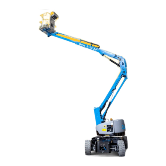
2 Manual storage container 9 Ground controls 3 Sliding mid-rail 10 Power to charger (between tires) 4 Lanyard anchorage point 11 Steer tire 5 Platform 12 Battery box 6 Platform controls 13 Non-steer tire 7 Primary boom Part No. 1257143 Z-33/18... -
Page 20: Controls
11 Hour meter 3 Primary boom extend/retract switch 4 Primary boom up/down switch 5 Platform overload indicator light 6 Key switch for platform/off/ground selection 7 Red Emergency Stop button 8 Secondary boom up/down switch 9 Function enable button Z-33/18 Part No. 1257143... - Page 21 5 Platform overload indicator light 11 Hour meter Light flashing indicates the platform is overloaded and no functions will operate. Remove weight until the light goes off. Part No. 1257143 Z-33/18...
- Page 22 6 Red Emergency Stop button 13 Thumb rocker switch for primary boom extend/ 7 Proportional control handle for drive function retract function and thumb rocker for steer function 14 Emergency lowering switch 8 Drive enable indicator light Z-33/18 Part No. 1257143...
- Page 23 6 Red Emergency Stop button of the machine functions. Push in the red Emergency Stop button to the off position to stop all functions. Pull out the red Emergency Stop button to the on position to operate the machine. Part No. 1257143 Z-33/18...
- Page 24 14 Emergency lowering switch Use emergency power if the primary power source fails. Simultaneously hold the emergency lowering switch to either side and activate the desired function. Z-33/18 Part No. 1257143...
-
Page 25: Inspections
Scheduled maintenance inspections shall be performed by qualified service technicians, according to the manufacturer’s specifications and the requirements listed in the responsibilities manual. Part No. 1257143 Z-33/18... - Page 26 Electrical components, wiring and electrical latched. cables Hydraulic hoses, fittings, cylinders and manifolds Hydraulic tank Drive and turntable motors and drive hubs Wear pads Tires and wheels Limit switches and horn Alarms and beacons (if equipped) Z-33/18 Part No. 1257143...
- Page 27 3 Always perform function tests prior to service. use. Know and understand the function tests before going on to the next section. 4 Inspect the workplace. 5 Only use the machine as it was intended. Part No. 1257143 Z-33/18...
- Page 28 7 Press and hold the function enable button and activate each boom and platform function toggle switch. Result: All boom and platform functions should operate through a full cycle. The descent alarm should sound while the boom is lowering. Z-33/18 Part No. 1257143...
- Page 29 Result: The steer wheels should turn in the direction that the yellow triangles point on the Test the Foot Switch drive chassis. 20 Do not press down the foot switch and test each machine function. Result: No functions should operate. Part No. 1257143 Z-33/18...
- Page 30 Note: When the drive enable system is in use, the machine may drive in the opposite direction that the drive and steer control handle is moved. Use the color-coded direction arrows on the platform controls and the drive chassis to identify the direction of travel. Z-33/18 Part No. 1257143...
- Page 31 43 Rotate the turntable until the primary boom moves past one of the non-steer wheels. 44 Extend the primary boom approximately 10 cm. 45 Slowly move the drive control handle to the full drive position. Part No. 1257143 Z-33/18...
- Page 32 It is the operator’s responsibility to read and remember the workplace hazards, then watch for and avoid them while moving, setting up and operating the machine. Z-33/18 Part No. 1257143...
- Page 33 Use the pictures on the next page to verify that all 1258982 Label — Wheel Load decals are legible and in place. 1258499 Label — Lifting Diagram, Z-33/18 Below is a numerical list with quantities and 114248 Label — Tip-over Hazard, Tilt descriptions.
- Page 34 Safety Tape 1258501 Safety Tape 52969 114252 Shading indicates 28174 72086 40434 decal is hidden from view, i.e. under covers 114252 1262127 133067 Safety Tape 114249 1258982 1258499 72086 52475 1262127 09.4618.1625 1258982 114249 52475 72086 1258498 Z-33/18 Part No. 1257143...
-
Page 35: Operating Instructions
4 Inspect the workplace. That means every new operator should perform 5 Only use the machine as it was intended. a pre-operation inspection, function tests, and a workplace inspection before using the machine. Part No. 1257143 Z-33/18... - Page 36 To Position Platform 1 Push and hold the function enable button. 2 Move the appropriate toggle switch according to the markings on the control panel. Drive and steer functions are not available from the ground controls. Z-33/18 Part No. 1257143...
- Page 37 20% (11°) Maximum side slope rating: 25% (14°) Note: Slope rating is subject to ground conditions and adequate traction. Be sure the boom is below horizontal and the platform is between the circle-end wheels. Part No. 1257143 Z-33/18...
- Page 38 0.3 m ÷ 3.6 m = 0.083; 0.083 x 100 = 8.3% grade If the slope exceeds the maximum uphill, downhill or side slope rating, then the machine must be winched or transported up or down the slope. See Transport and Lifting section. Z-33/18 Part No. 1257143...
- Page 39 If the tilt alarm sounds with overloaded. For information on how to reset this the platform uphill: message, please consult the appropriate Genie Service Manual. 1 Lower the primary boom. After Each Use 2 Lower the secondary 1 Select a safe parking location–firm level...
- Page 40 Use proper AC input voltage for charging as to the bottom of the fill tube. Do not overfill. indicated on the charger. Use only Genie authorized batteries and charger. Dry Battery Filling and Do not operate the machine with the battery Charging Instructions charger plugged in.
-
Page 41: Transport And Lifting Instuctions
US Department of Transportation regulations, other localized regulations, and their company policy. Genie customers needing to containerize any lift or Genie product should source a qualified Free-wheel Configuration for freight forwarder with expertise in preparing, Winching loading and securing construction and lifting equipment for international shipment. - Page 42 0.125" (h x w): 3.5 x 5.5 s artwork may not be modified or ut author approval. s the property of Genie Industries Operator's Manual First edition • First Printing surrendered upon request. Transport and Lifting Instructions by Genie Industries...
- Page 43 Be sure the crane capacity, loading surfaces Center of gravity X Axis Y Axis and straps or lines are sufficient to withstand Z-33/18 925,3 mm 682 mm the machine weight. See the serial label for the 36,4 in 26,9 in machine weight.
-
Page 44: Maintenance
Dispose of material in accordance with Result: The hydraulic oil level should be at the governmental regulations. full black mark of the sight gauge. Use only Genie approved replacement parts. 3 Add oil as needed. Do not overfill. Hydraulic oil specifications Maintenance Symbols Legend... - Page 45 Do not overfill. 6 Install the vent caps. Note: Adding terminal protectors and a corrosion preventative sealant will help eliminate the corrosion on the battery terminals and cables. Part No. 1257143 Z-33/18...
-
Page 46: Specifications
Drive speed, booms raised and 0.86 km/h (0.24 m/s) be used only with adequate safety factors. retracted* Continuous improvement of our products is a Genie Drive speed, booms extended** 0.23 km/h (0.06 m/s) policy. Product specifications are subject to change 14.6 cm Ground clearance, axle without notice or obligation. - Page 47 First edition • First Printing Operator's Manual Specifications Range of Motion Chart FEET Part No. 1257143 Z-33/18...
- Page 48 Operator's Manual First edition • First Printing Specifications METERS Z-33/18 Part No. 1257143...
- Page 50 www.genielift.com...