Siemens SIMATIC IPC647D Operating Instructions Manual
Hide thumbs
Also See for SIMATIC IPC647D:
- Operating instructions manual (40 pages) ,
- Operating manual (54 pages) ,
- Product information (16 pages)
Table of Contents
Advertisement
Quick Links
SIMATIC IPC647D
SIMATIC
Industrial PC
SIMATIC IPC647D
Operating Instructions
Additional information
"BIOS Description" Operating Manual:
Detailed description of the BIOS setup and the setup parameters
"SIMATIC IPC647D/847D Hardware RAID Configuration" Compact Operating Instructions:
Detailed description of the Hardware RAID systems
01/2014
A5E32996306-AA
___________________
Preface
___________________
Overview
___________________
Safety Instructions
Installing and connecting the
___________________
device
___________________
Commissioning the device
___________________
Extended device functions
Expanding and assigning
___________________
parameters to the device
Device maintenance and
___________________
repair
___________________
Technical specifications
___________________
Technical support
___________________
Abbreviations
1
2
3
4
5
6
7
8
A
B
Advertisement
Table of Contents

Related Manuals for Siemens SIMATIC IPC647D


Summary of Contents for Siemens SIMATIC IPC647D
- Page 1 Technical specifications ___________________ Technical support ___________________ Abbreviations Additional information "BIOS Description" Operating Manual: Detailed description of the BIOS setup and the setup parameters "SIMATIC IPC647D/847D Hardware RAID Configuration" Compact Operating Instructions: Detailed description of the Hardware RAID systems 01/2014 A5E32996306-AA...
- Page 2 Note the following: WARNING Siemens products may only be used for the applications described in the catalog and in the relevant technical documentation. If products and components from other manufacturers are used, these must be recommended or approved by Siemens. Proper transport, storage, installation, assembly, commissioning, operation and maintenance are required to ensure that the products operate safely and without any problems.
-
Page 3: Preface
General knowledge in the field automation control engineering is recommended. Validity of the Operating Instructions These operating instructions are valid for all supplied versions of the SIMATIC IPC647D. Scope of this documentation The documentation for the SIMATIC IPC647D includes the following sections: ●... - Page 4 Preface SIMATIC IPC647D Operating Instructions, 01/2014, A5E32996306-AA...
-
Page 5: Table Of Contents
COM, DP, DVI/VGA, PS/2 and audio lines .................. 44 3.3.7 Multi-monitoring..........................44 Commissioning the device ........................45 General information on commissioning ..................45 Switching on the device ....................... 46 Automatic switching on of the device ................... 47 Windows Action Center ........................ 47 SIMATIC IPC647D Operating Instructions, 01/2014, A5E32996306-AA... - Page 6 Device maintenance and repair ......................83 Repair information ........................83 Maintenance ..........................84 7.2.1 Maintenance intervals ......................... 84 7.2.2 Changing the filter pad ........................ 84 Removing and installing hardware ....................85 7.3.1 Replacing device fans ......................... 85 SIMATIC IPC647D Operating Instructions, 01/2014, A5E32996306-AA...
- Page 7 Motherboard ..........................132 8.5.1.1 Structure and functions of the motherboard ................132 8.5.1.2 Technical features of the motherboard ..................133 8.5.1.3 Position of the interfaces on the motherboard ................135 8.5.1.4 External interfaces ........................136 SIMATIC IPC647D Operating Instructions, 01/2014, A5E32996306-AA...
- Page 8 Technical support..........................191 Service and support ........................191 Troubleshooting ........................192 RAID system and device startup ....................195 Notes on the use of third-party modules ................... 196 Abbreviations ............................197 Glossary .............................. 203 Index ..............................215 SIMATIC IPC647D Operating Instructions, 01/2014, A5E32996306-AA...
-
Page 9: Overview
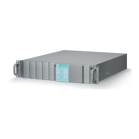
Overview Product description The SIMATIC IPC647D is an industrial PC in 19" rack format design. The SIMATIC IPC647D has the following characteristic features: ● High-performance industrial functionality ● Highly compact ● Extremely rugged ● Extensive product continuity The SIMATIC IPC offers system integrators, cabinet designers, system engineers and machine designers a 19"... -
Page 10: Highlights
● RAID1 – redundant data storage on two hard drives, also "hot swap" in connection with removable drive bays (Hot Spare equipping is supported) ● Optional ECC memory module ● Redundant power supply with status message SIMATIC IPC647D Operating Instructions, 01/2014, A5E32996306-AA... -
Page 11: Features
PS/2 Mouse PS/2 Audio Microphone, Line out / Headset Power supply 100 VAC to 240 VAC, wide range; with short-term power failure backup in accordance with NAMUR: Max. 20 ms at 0.85 rated voltage SIMATIC IPC647D Operating Instructions, 01/2014, A5E32996306-AA... - Page 12 4 DIMM base with or without ECC Drives Hard disks 3.5" SATA 6 Gbit/s, 500 GB / 1000 GB Optical drive Slimline SATA Memory expansions ≥4 GB can only be used in combination with 64-bit operating systems. SIMATIC IPC647D Operating Instructions, 01/2014, A5E32996306-AA...
- Page 13 , 64 bit • Windows 7, MUI , 32 bit / 64 bit • Power supplies Redundant AC power supply Monitored AC-100/230 V power supply, 350 W MUI: German, English, French, Spanish and Italian SIMATIC IPC647D Operating Instructions, 01/2014, A5E32996306-AA...
- Page 14 Monitoring modules of the redundant power supply • System / Ethernet monitoring (Heartbeat) • SIMATIC IPC Image & Partition Software tool for local data backup and setting up of the hard Creator V3.3.2 or higher disks. SIMATIC IPC647D Operating Instructions, 01/2014, A5E32996306-AA...
-
Page 15: Design Of The Device
DVD burner drive, Slimline • ④ Status displays HDD in vibration-damped drive cage • SSD in internal drive cage • ⑤ ⑩ Reset button Lock for front door ⑥ USB 2.0 port ⑦ USB 3.0 port SIMATIC IPC647D Operating Instructions, 01/2014, A5E32996306-AA... - Page 16 Acknowledgment button ③ Module 1 of the redundant power supply ④ Module 2 of the redundant power supply ⑤ On/off switch ⑥ Status LED module 1 ⑦ Interfaces (Page 17) ⑧ Expansion card slots SIMATIC IPC647D Operating Instructions, 01/2014, A5E32996306-AA...
-
Page 17: Interfaces
Slots for expansion cards (behind slot plate) ⑥ ⑭ DisplayPort port DMS59 connector ⑦ ⑮ PS/2 interface for keyboard DVI-I connector ⑧ ⑯ PS/2 interface for mouse VGA adapter Depending on the ordered device configuration SIMATIC IPC647D Operating Instructions, 01/2014, A5E32996306-AA... -
Page 18: Status Displays
SF PROFINET, Status CP not available • optional CP 1616 onboard CP disabled • No error, communication established • Charging in progress • CP 1616 driver not installed • CP in NDIS mode • SIMATIC IPC647D Operating Instructions, 01/2014, A5E32996306-AA... - Page 19 Error in early BIOS All lit CPU has not started up Post Error in early POST For unique labeling, the Ethernet ports are numbered on the enclosure. The numbering by the operating system may deviate from this. SIMATIC IPC647D Operating Instructions, 01/2014, A5E32996306-AA...
- Page 20 Interface disabled • Connection • No activity • Goes out Activity briefly For unique labeling, the LAN and PROFINET interface are numbered on the enclosure. The numbering by the operating system may deviate from this. SIMATIC IPC647D Operating Instructions, 01/2014, A5E32996306-AA...
- Page 21 The two "virtual" CP -1616 LEDs are only visible in the SIMATIC user interface and can be read via SNMP. PROFINET Virtual LEDs CP is active STOP CP is in the stop state Flashes The states "flashes slowly" and "flashes rapidly" do not exist. SIMATIC IPC647D Operating Instructions, 01/2014, A5E32996306-AA...
-
Page 22: Accessories
Information about the accessories that can be ordered is available in the following table and on the Internet under the following address: ● IPC expansion components (http://www.automation.siemens.com/mcms/pc-based- automation/en/industrial-pc/expansion_components_accessories) ● Industry Mall (http://mall.automation.siemens.com) Name Description Order Number and Figure Retainer for locking... -
Page 23: Safety Instructions
When you open the control cabinet, some areas or components may be carrying life- threatening voltages. If you touch these areas or components, you may be killed by electric shock. Switch off the power supply to the cabinet before opening it. SIMATIC IPC647D Operating Instructions, 01/2014, A5E32996306-AA... - Page 24 • Do not throw lithium batteries into fire, do not solder on the cell body, do not recharge, do not open, do not short-circuit, do not reverse polarity, do not heat above 100°C and protect from direct sunlight, moisture and condensation. SIMATIC IPC647D Operating Instructions, 01/2014, A5E32996306-AA...
- Page 25 ESD directive in the technical specifications. IT Security Siemens offers automation and drive products with industrial security functions that support the secure operation of plants and machines. They are important components for an integrated industrial security concept. The products undergo continual development with this aspect in mind.
-
Page 26: Notes On Use
The device is tested and certified on the basis of the technical standards. In rare cases, functional restrictions can occur during plant operation. Validate the correct functioning of the plant to avoid functional restrictions. SIMATIC IPC647D Operating Instructions, 01/2014, A5E32996306-AA... - Page 27 • Do not obstruct the venting slots of the device. Note Use in an industrial environment without additional protective measures This device was designed for use in a normal industrial environment according to IEC 60721-3-3. SIMATIC IPC647D Operating Instructions, 01/2014, A5E32996306-AA...
- Page 28 Safety Instructions 2.2 Notes on use SIMATIC IPC647D Operating Instructions, 01/2014, A5E32996306-AA...
-
Page 29: Installing And Connecting The Device
Death or serious injury could occur. Make sure that the damaged device is not inadvertently installed and put into operation. Label the damaged device and keep it locked away. Send off the device for immediate repair. SIMATIC IPC647D Operating Instructions, 01/2014, A5E32996306-AA... -
Page 30: Identification Data Of The Device
Noting down the device identification data Enter the following data in the table below: Serial number S VP ... Order no. 6AG4112-2 ... Microsoft Windows Product Key Ethernet 1 address Ethernet 2 address CP 1616 onboard layer 2 SIMATIC IPC647D Operating Instructions, 01/2014, A5E32996306-AA... -
Page 31: Permitted Mounting Positions
The device can be mounted horizontally in control desks, switching cabinets and 19" rack systems. NOTICE Operation in closed rooms The device is approved for operation in closed rooms only. Pay attention to the ambient and environmental conditions. SIMATIC IPC647D Operating Instructions, 01/2014, A5E32996306-AA... -
Page 32: Mounting The Device
● Install the device in such a way that it does not pose a danger, for example, by falling over. Note For more details, consult the "Technical Data" in the "Ambient conditions" chapter. SIMATIC IPC647D Operating Instructions, 01/2014, A5E32996306-AA... - Page 33 The following figure highlights the mounting holes for the angle brackets and for the telescopic rails. The dimensions for the mounting holes are listed in the chapter "Dimension drawing of the telescopic rails (Page 122)". SIMATIC IPC647D Operating Instructions, 01/2014, A5E32996306-AA...
-
Page 34: Connecting The Device
Note Ensure that the shockproof power outlet of the building installation is freely accessible and as close as possible to the device, especially if the power plug is secured by a power plug latch. SIMATIC IPC647D Operating Instructions, 01/2014, A5E32996306-AA... -
Page 35: Connection Of Equipotential Bonding
2. Connect the equipotential bonding cable with the central grounding point of the cabinet in which the device is installed. Ensure that the equipotential bonding cable has a large-area contact with the central grounding point. SIMATIC IPC647D Operating Instructions, 01/2014, A5E32996306-AA... -
Page 36: Connecting Peripheral Equipment
• The computer in question must be turned off and the power supply connector should be plugged in. • During the measurement, all cables from the plant to the computer should be connected. • All other components in the plant must be active. SIMATIC IPC647D Operating Instructions, 01/2014, A5E32996306-AA... -
Page 37: Connecting The Power Supply
Use a flexible power cord which is approved to UL and CSA with the following features: SJT model with three conductors, min. 18 AWG conductor cross-section, max. length 4.5 m, and tandem grounded connector 15 A, min. 250 V. SIMATIC IPC647D Operating Instructions, 01/2014, A5E32996306-AA... -
Page 38: Connecting An Ac Power Supply
For installation, follow the steps for removal in reverse order. WARNING Risk of fire If the power plug is secured with a clamp, the power outlet must be freely accessible to allow the device to be easily removed from the mains. SIMATIC IPC647D Operating Instructions, 01/2014, A5E32996306-AA... -
Page 39: Connecting A Redundant Power Supply
When the power plug is secured with a latch, the power outlet must be freely accessible to allow the device to be easily removed from the mains. Installation Install the device in reverse order. SIMATIC IPC647D Operating Instructions, 01/2014, A5E32996306-AA... -
Page 40: Connecting The Device To Networks
Use this software package to configure network components and connections. You will find information on this on the SIMATIC NET DVD. This software package and the documentation are not part of the product package. SIMATIC IPC647D Operating Instructions, 01/2014, A5E32996306-AA... - Page 41 Additional information Additional information is available in the catalog and the online ordering system Industry Mall (http://mall.automation.siemens.com). See also Technical Support (http://www.siemens.de/automation/csi_en_WW) CP 1616 onboard The basic characteristics of the PCS 1616 onboard are: ● Optimized for PROFINET IO ● With Ethernet realtime ASIC ERTEC 400 ●...
- Page 42 Read this guide if you want to install the NDIS device Device Driver CP16xx.sys driver, CP16xx.sys. Further information You can find the information on specific products in the Internet at the address: Product- related Information SIMATIC NET (http://www.siemens.com/simatic-net) SIMATIC IPC647D Operating Instructions, 01/2014, A5E32996306-AA...
-
Page 43: Securing The Lines
1. Remove the marked screw and the fieldbus cover fastened with it. 2. Mount the strain relief. Use the mounting screw of the fieldbus cover for this purpose. 3. Fasten the cables with cable ties to the cable strain relief. SIMATIC IPC647D Operating Instructions, 01/2014, A5E32996306-AA... -
Page 44: Com, Dp, Dvi/Vga, Ps/2 And Audio Lines
● 1 × DisplayPort, 1 × VGA via DisplayPort-VGA adapter, 1 × DVI/VGA Note The motherboard supports up to one additional DVI monitor if it is connected by means of a passive DisplayPort-DVI adapter. SIMATIC IPC647D Operating Instructions, 01/2014, A5E32996306-AA... -
Page 45: Commissioning The Device
● The power supply is connected. ● An operating system is installed. The device can be supplied without an operating system. Information on installation of the operating system is available in the section "Installing the software". SIMATIC IPC647D Operating Instructions, 01/2014, A5E32996306-AA... -
Page 46: Switching On The Device
The product key is located on the "Certificate of Authentication" in the "Product Key" line, see section "Identification data of the device (Page 30)". Result The interface of the operating system is displayed every time you turn on the device and after the startup routine. SIMATIC IPC647D Operating Instructions, 01/2014, A5E32996306-AA... -
Page 47: Automatic Switching On Of The Device
● Real-time protection (Windows 7 only): Windows Defender displays warnings if spyware or possibly unwanted software is installed or executed on the computer. You will also receive a warning if programs attempt to modify important Windows settings. Configure the Security Center according to your requirements. SIMATIC IPC647D Operating Instructions, 01/2014, A5E32996306-AA... -
Page 48: Notes On Different Device Configurations
Data comparison is the only guarantee that data has been written correctly. Perform data comparison each time you burn a disc. See also Technical specifications (Page 123) SIMATIC IPC647D Operating Instructions, 01/2014, A5E32996306-AA... -
Page 49: Replacing Hard Disks
7. Fold back the tray bracket until it rests completely against the hard disk tray. ② The power supply LED must be on. 8. Slide the cover of the removable drive bay lock to the left. 9. Lock it with the appropriate key. SIMATIC IPC647D Operating Instructions, 01/2014, A5E32996306-AA... -
Page 50: System With Two Drives
"Drivers\RAID\Intel" directory on the "Documentation and Drivers" DVD that ships with the product. Additional information on RAID1 systems can be found in the section "Managing RAID systems (Page 104)". See also Replacing a defective hard disk drive in the RAID system (Page 80) SIMATIC IPC647D Operating Instructions, 01/2014, A5E32996306-AA... -
Page 51: Switching Off The Device
If the device was mounted in a control cabinet: ● Shut down the operating system and switch the AC circuit breaker to "Off". The device is switched off and fully disconnected from the mains voltage. No trickle current is flowing. SIMATIC IPC647D Operating Instructions, 01/2014, A5E32996306-AA... - Page 52 ● Press the on/off button for more than 4 seconds. ● Press the Reset button. Information on the position of the button is available in the section "Device views (Page 15)". See also Device views (Page 15) SIMATIC IPC647D Operating Instructions, 01/2014, A5E32996306-AA...
-
Page 53: Extended Device Functions
SIMATIC IPC DiagMonitor is available on CD (not included in the scope of delivery). This monitoring software comprises: ● The software for the stations to be monitored. ● A library for creating user-specific applications. SIMATIC IPC647D Operating Instructions, 01/2014, A5E32996306-AA... -
Page 54: Temperature Monitoring/Display
The following reactions may be triggered if the watchdog is not retriggered within the set time: Reaction Option Switch watchdog LED to red None Trigger a PC reset Configurable Output of DiagBase alarm messages None Note For more information on the watchdog functions, contact Customer Support. SIMATIC IPC647D Operating Instructions, 01/2014, A5E32996306-AA... -
Page 55: Fan Monitoring
When the first warning level is reached, the remaining service life of the battery for buffering CMOS data and buffer memory is at least 1 month. 5.1.6 Drive monitoring Default: SMART messages of the hard disks are reported. RAID combination: The "Normal", "Degraded", "Rebuild" are displayed. SIMATIC IPC647D Operating Instructions, 01/2014, A5E32996306-AA... -
Page 56: Active Management Technology (Amt)
SIMATIC IPC Remote Manager The "SIMATIC IPC Remote Manager" software is available for utilization of the AMT functions with SIMATIC IPCs. The software can be ordered from the Siemens online ordering system. For detailed information about "SIMATIC IPC Remote Manager", refer to the corresponding product documentation. -
Page 57: Trusted Platform Module (Tpm)
The warranty does not cover a reset of the hardware in the event of a loss of a password. Please store the password carefully and make sure it is protected against unauthorized access. SIMATIC IPC647D Operating Instructions, 01/2014, A5E32996306-AA... - Page 58 Extended device functions 5.3 Trusted Platform Module (TPM) SIMATIC IPC647D Operating Instructions, 01/2014, A5E32996306-AA...
-
Page 59: Expanding And Assigning Parameters To The Device
Distribution to the slots without exceeding the total power: ● 25 W for Slot 1 maximum ● 25 W each for Slot 2, 3 maximum ● 15 W for Slot 4 maximum Maximum permitted configuration SIMATIC IPC647D Operating Instructions, 01/2014, A5E32996306-AA... - Page 60 ● 15 W for Slot 4 maximum Maximum permitted configuration Note During operation, the HDDs installed in the removable drive bay must not be exposed to vibratory loads and may only be exposed to limited shock loads (see Technical specifications). SIMATIC IPC647D Operating Instructions, 01/2014, A5E32996306-AA...
- Page 61 ● 10 W for Slot 4 maximum Maximum permitted configuration Note During operation, the HDDs installed in the removable drive bay must not be exposed to vibratory loads and may only be exposed to limited shock loads (see Technical specifications). SIMATIC IPC647D Operating Instructions, 01/2014, A5E32996306-AA...
-
Page 62: Removing The Front Panel
Observe the chapter "ESD guideline (Page 119)". 1. Open the front door at least 45°. The interlock marked in the figure then releases the front panel. 2. Remove the front panel. To do so reach into the fan slots. SIMATIC IPC647D Operating Instructions, 01/2014, A5E32996306-AA... -
Page 63: Open The Device
Disclaimer of liability All technical specifications and approvals apply only to expansions which are approved by the Siemens AG. We are not liable for functional limitations caused by the use of third-party devices or components. Observe the installation instructions for the components. UL approval of the device only applies when UL-approved components are used according to their "Conditions of... -
Page 64: Removing And Installing Memory Modules
Requirement ● The device is opened. ● Remove the bus board, if necessary, for easier access to the memory modules. SIMATIC IPC647D Operating Instructions, 01/2014, A5E32996306-AA... - Page 65 The memory module latches in audibly. The memory module is inserted correctly if less than 1 mm of the gold contacts is visible evenly across the entire length of the module. 5. Close the device. SIMATIC IPC647D Operating Instructions, 01/2014, A5E32996306-AA...
- Page 66 3. Close the device. Display of the current memory configuration The new memory configuration is detected automatically. The allocation of the ”base memory and extended memory” is automatically displayed when you switch on the device. SIMATIC IPC647D Operating Instructions, 01/2014, A5E32996306-AA...
-
Page 67: Expansion Cards
Compliance with the defined mechanical defaults is imperative. Failure to comply with these defaults can result in contact problems, malfunctions and assembly difficulties. The permitted expansion card contour dimensions are specified in the section Dimension drawing of the expansion cards (Page 122). SIMATIC IPC647D Operating Instructions, 01/2014, A5E32996306-AA... -
Page 68: Removing And Installing Bus Frame
The feet on the bus frame shown in the following figure serve as a mounting aid and allow vertical mounting. You may have to support the bus frame with your hand to prevent it from tipping. Requirement ● The device is open in accordance with section "Open the device. (Page 63)". SIMATIC IPC647D Operating Instructions, 01/2014, A5E32996306-AA... - Page 69 Support the bus frame with your hand to prevent it from tipping. Unlock the marked plug and pull out the connector downwards. Installation To install the bus frame follow the steps for removing it in reverse order. SIMATIC IPC647D Operating Instructions, 01/2014, A5E32996306-AA...
-
Page 70: Removing And Installing Expansion Cards
To guarantee the stable installation of a low expansion card, you need an additional mounting bracket for latching retainers. The mounting bracket may have to be removed when you replace the low expansion card with a high one. SIMATIC IPC647D Operating Instructions, 01/2014, A5E32996306-AA... - Page 71 The retainer can only be moved in the direction of the expansion card. The retainer latches into the selected position. If you want to change the position subsequently, you have to open the top edge of the bus frame. SIMATIC IPC647D Operating Instructions, 01/2014, A5E32996306-AA...
- Page 72 1. Install the bus frame into the device in accordance with the chapter "Removing and installing bus frame (Page 68)". See also System resources (Page 159) BIOS description (Page 169) Bus board (Page 153) Bus board models (Page 153) SIMATIC IPC647D Operating Instructions, 01/2014, A5E32996306-AA...
-
Page 73: Drives And Storage Media
The drive cage contains shock and vibration-attenuating components for holding hard disk drives. A Slimline DVD drive can be mounted in the lower drive bay. ① Two drive bays ② Slimline mounting bay for DVD drive ③ Vibration-damped drive cage SIMATIC IPC647D Operating Instructions, 01/2014, A5E32996306-AA... -
Page 74: Removing And Installing Drive Cage
Slimline drive marked on the right, if a Slimline drive exists. 4. Slide the drive cage toward the power supply until it is released from the front frame and remove the drive cage from the device. SIMATIC IPC647D Operating Instructions, 01/2014, A5E32996306-AA... -
Page 75: Removing And Installing Drive Fans
2. Put your hands into the indentations on the left and right of the fan retainer and slide the fan retainer together with the ② drive fan up and out of the guides. SIMATIC IPC647D Operating Instructions, 01/2014, A5E32996306-AA... - Page 76 If necessary, remove the adapter plug, for example, when removing the drive cage. ① 1. To do so, press on the clips the side of the adapter plug and remove the plug by pulling it down. SIMATIC IPC647D Operating Instructions, 01/2014, A5E32996306-AA...
-
Page 77: Removing And Inserting The Tray From The Removable Drive Bays
4. Now grasp the handle to the right of the notch you used to pull out the handle and pull the tray completely out of the removable drive bay. SIMATIC IPC647D Operating Instructions, 01/2014, A5E32996306-AA... -
Page 78: Removing And Installing The Hard Disk Drive From A Tray
Remove the marked screws. Installation Proceed in reverse order. Use only the original screws during installation. Position all screws first and do not tighten them until all screws are installed in the thread. SIMATIC IPC647D Operating Instructions, 01/2014, A5E32996306-AA... -
Page 79: Removing And Installing A Drive From A Drive Cage
4. Pull the removable drive bay out of the drive cage in the direction of the arrow. Installation To install the fan, follow the steps for removing it in reverse order. Use only the original screws during installation. SIMATIC IPC647D Operating Instructions, 01/2014, A5E32996306-AA... -
Page 80: Replacing A Defective Hard Disk Drive In The Raid System
Internal hard disk drive or hard disk drive in removable drive bay Status display RAID BIOS RAID software SATA connection of Drive the motherboard HDD0 alarm Port 0 Device port 0 SATA 0 HDD1 alarm Port 1 Device port 1 SATA 1 SIMATIC IPC647D Operating Instructions, 01/2014, A5E32996306-AA... -
Page 81: Removing And Installing An Ssd
For installation, follow the steps for removal in reverse order. Use only the original screws during installation. Position all screws first and do not tighten them until all screws are installed in the thread. SIMATIC IPC647D Operating Instructions, 01/2014, A5E32996306-AA... -
Page 82: Removing And Installing An Ssd With Mounting Plate From A Drive Cage
4. Remove the mounting plate from the SSD. 5. Pull out the plug from the SSD. Installation To install the fan, follow the steps for removing it in reverse order. Use only the original screws during installation. SIMATIC IPC647D Operating Instructions, 01/2014, A5E32996306-AA... -
Page 83: Device Maintenance And Repair
UL approval of the device only applies when the UL-approved components are used according to their "Conditions of Acceptability". We are not liable for functional limitations caused by the use of third-party devices or components. SIMATIC IPC647D Operating Instructions, 01/2014, A5E32996306-AA... -
Page 84: Maintenance
● A filter mat You may only use filter mats of the same type. Information about original spare parts for SIMATIC IPCs is available on the Internet at: SIMATIC IPC after-sales information system (http://www.siemens.com/asis). Order no.: A5E02396171; 10 pieces per package SIMATIC IPC647D... -
Page 85: Removing And Installing Hardware
● The device is fully disconnected from the mains voltage, see chapter "Switching off the device (Page 51)". ● The front panel is removed, see chapter "Removing the front panel (Page 62)". ● 1 or 2 fans Procedure Read the section "ESD guideline (Page 119)". SIMATIC IPC647D Operating Instructions, 01/2014, A5E32996306-AA... - Page 86 To install the fan, follow the steps for removing it in reverse order. Ensure that position of the fans are the cable routing are correct, see the figure in the "Removal" section, Step 2. Make sure that the cables are not squashed or block the fan. SIMATIC IPC647D Operating Instructions, 01/2014, A5E32996306-AA...
-
Page 87: Replacing The Backup Battery
• Replace the lithium battery only with an identical one or a type recommended by the manufacturer. Information about original spare parts for SIMATIC IPCs is available on the Internet at: SIMATIC IPC after-sales information system (http://www.siemens.com/asis) Requirement ● The current BIOS Setup settings, see chapter "BIOS description (Page 169)". - Page 88 2. Dispose of the battery properly. Installation 1. Press the new battery centered into the socket applying slight pressure. Ensure that the battery is then held by the 4 brackets. SIMATIC IPC647D Operating Instructions, 01/2014, A5E32996306-AA...
-
Page 89: Removing The Ac Power Supply
● The power connector has been removed, see chapter "Connecting an AC power supply (Page 38)". ● The bus frame has been removed, see chapter "Removing and installing bus frame (Page 68)". ● T10 screwdriver ● Cable ties SIMATIC IPC647D Operating Instructions, 01/2014, A5E32996306-AA... - Page 90 2. Remove the marked screws. 3. Push the power supply unit towards the drive cage and lift it out of the device. Installation Install the device in reverse order. See also Connection information (Page 34) SIMATIC IPC647D Operating Instructions, 01/2014, A5E32996306-AA...
-
Page 91: Replacing The Redundant Power Supply
1. Remove the marked screw at the defective module. 2. Pull out the defective module from the frame using the hinged handle. 3. Insert the new module and secure it with the screw. 4. Reconnect the power supply cables. SIMATIC IPC647D Operating Instructions, 01/2014, A5E32996306-AA... -
Page 92: Replacing The Redundant Power Supply Completely
● The bus frame has been removed, see chapter "Removing and installing bus frame (Page 68)". ● 1 spare part "Redundant power supply" ● 1 T10 screwdriver ● 1 crosstip screwdriver ● 2 cable ties SIMATIC IPC647D Operating Instructions, 01/2014, A5E32996306-AA... - Page 93 Installation Install the device in reverse order. Secure the cables using the cable clips available in the device as well as with new cable ties. SIMATIC IPC647D Operating Instructions, 01/2014, A5E32996306-AA...
-
Page 94: Removing And Installing The Piggyback And Bus Board
3. Guide the angle connector of the piggyback through the middle rail of the bus frame and remove the piggyback as shown in the following figure. SIMATIC IPC647D Operating Instructions, 01/2014, A5E32996306-AA... -
Page 95: Removing The Op
● The device is open, see the section "Open the device. (Page 63)". ● The bus frame has been removed, see chapter "Removing and installing bus frame (Page 68)". ● 1 operator panel ● 1 crosstip screwdriver Procedure Read the section "ESD guideline (Page 119)". SIMATIC IPC647D Operating Instructions, 01/2014, A5E32996306-AA... - Page 96 3. Remove the USB connector. 4. Remove the marked screws and then the operator panel. 5. Loosen the white flat cable at the ② plug connector by sliding the ① lock to the left. SIMATIC IPC647D Operating Instructions, 01/2014, A5E32996306-AA...
-
Page 97: Removing And Installing The Processor Cooler
● The bus frame has been removed, see chapter "Removing and installing bus frame (Page 68)". ● 1 processor cooler Information about original spare parts for SIMATIC IPCs is available on the Internet at: SIMATIC IPC after-sales information system (http://www.siemens.com/asis) ● 1 T10 screwdriver SIMATIC IPC647D Operating Instructions, 01/2014, A5E32996306-AA... - Page 98 Tighten the screws at the heat sink gradually cross- wise. Avoid uneven tightening as this may result in a tensioning of the heat sink. Further procedure 1. Install the bus frame. 2. Close the device. SIMATIC IPC647D Operating Instructions, 01/2014, A5E32996306-AA...
-
Page 99: Removing The Motherboard
● 1 motherboard Information about original spare parts for SIMATIC IPCs is available on the Internet at: SIMATIC IPC after-sales information system (http://www.siemens.com/asis). The motherboard is supplied as a spare part with soldered-on processor - but without processor heat sink, memory modules and bus board. - Page 100 3. Use a hex key to remove the hex bolts marked in the following figure.. The following figure shows the PROFIBUS device with MPI/DP interface. Only the two middle screws of the COM1 port have to be loosened at the other device variants. SIMATIC IPC647D Operating Instructions, 01/2014, A5E32996306-AA...
-
Page 101: Replacing The Processor
If the processor type is changed, the BIOS must be updated so that the suitable microcode is loaded. Information about original spare parts for SIMATIC IPCs is available on the Internet at: – SIMATIC IPC after-sales information system (http://www.siemens.com/asis) – Contacts (http://www.siemens.com/automation/partner) SIMATIC IPC647D... - Page 102 Do not touch the contacts of the processor in the process. NOTICE Damage to the motherboard Do not touch the contacts of the processor base when the processor is removed. Ensure that the base id free of soiling or foreign matter. SIMATIC IPC647D Operating Instructions, 01/2014, A5E32996306-AA...
- Page 103 The processor is then not held correctly in place by the holding frame. The result may be malfunctions. Therefore use only a low level of force and if a fault occurs, swivel the lever back. Eliminate the cause of the fault. SIMATIC IPC647D Operating Instructions, 01/2014, A5E32996306-AA...
-
Page 104: Managing Raid Systems
Managing RAID systems 7.4.1 Example for a RAID1 system during the boot phase of the system You can configure RAID hardware with <CTRL-I>. The associated description is available on the "Documentation and Drivers" DVD. SIMATIC IPC647D Operating Instructions, 01/2014, A5E32996306-AA... -
Page 105: Raid Software
Execution of keyboard, mouse or touch screen commands may be briefly delayed in extreme situations. This could result in operator errors on the machine or plant. Do not operate safety-critical functions when a hard disk has failed. SIMATIC IPC647D Operating Instructions, 01/2014, A5E32996306-AA... -
Page 106: Displaying A Defective Hard Disk Of A Raid System In The Raid Software
To be able to boot from the RAID system, you must place it first in the list of bootable sources in the BIOS "Boot" setup menu. Otherwise, the system will boot from the hard disk you have just installed and the message "Operating system not found" will be displayed. SIMATIC IPC647D Operating Instructions, 01/2014, A5E32996306-AA... -
Page 107: Integrating A New Hard Disk Drive In The Raid System
Sequence The following figure is an example for the automatic rebuilding process. A defective hard disk is still displayed during the rebuilding process. This display disappears when the rebuilding process is completed. SIMATIC IPC647D Operating Instructions, 01/2014, A5E32996306-AA... - Page 108 The new hard disk is then assigned to a SATA port and is integrated into the RAID system. A defective hard disk is still displayed during the rebuilding process. This display disappears when the rebuilding process is completed. SIMATIC IPC647D Operating Instructions, 01/2014, A5E32996306-AA...
-
Page 109: Installing The Software
Note Before you install new drivers or operating system updates for Windows MUI versions, configure the regional menu and dialog settings and the default English (US) language. other operating systems Contact the corresponding manufacturer. SIMATIC IPC647D Operating Instructions, 01/2014, A5E32996306-AA... -
Page 110: Installing Drivers And Software
Installing the software ● You can find information about installing SIMATIC software packages in the corresponding documentation. ● You can obtain information about driver updates and installing application programs from the respective manufacturers. SIMATIC IPC647D Operating Instructions, 01/2014, A5E32996306-AA... -
Page 111: Installing Windows 7 Or Windows Server 2008 R2
Press any key to boot from CD or DVD .. After a few seconds, you will see the "Install Windows" installation program. 9. Now follow the instructions in the installation program. You can find additional information on this in the next section. SIMATIC IPC647D Operating Instructions, 01/2014, A5E32996306-AA... - Page 112 Please read the information in the section "Information for systems with RAID or AHCI controller". Drive options For display of additional functions that you can use to set up the data medium, (advanced) see figure "Windows installation window "Drive options (advanced)"". SIMATIC IPC647D Operating Instructions, 01/2014, A5E32996306-AA...
- Page 113 Information on how the data medium is partitioned in its factory state is available in the tables below. 2. Select the partition on which you want to install the operating system. 3. Click "Next". Installation is started. The Windows operating system is installed on the data medium. SIMATIC IPC647D Operating Instructions, 01/2014, A5E32996306-AA...
-
Page 114: Setting Up The Language Selection Using The Multilanguage User Interface (Mui)
Changing the settings for language, region and formats of a registered user account 1. Choose: "Start > Control Panel > Clock, Language, and Region > Regional and Language Options" 2. You can make the desired changes in the "Formats" and "Location und Keyboards and Languages" tabs. SIMATIC IPC647D Operating Instructions, 01/2014, A5E32996306-AA... -
Page 115: Restoring The Delivery State
All data on drive C: will be completely deleted, reformatted and overwritten with the original factory software. If "Restore entire drive" is set ALL data, user settings, authorizations or license keys will be lost on the entire drive. SIMATIC IPC647D Operating Instructions, 01/2014, A5E32996306-AA... -
Page 116: Installing The Raid Controller Software
Read the information in the Device_driver_CP16xx.pdf document on the supplied "Documentation and Drivers" DVD. PROFINET IO Read the information regarding the SIMATIC devices and SIMATIC NET documentation listed in the "Connecting the device" section. SIMATIC IPC647D Operating Instructions, 01/2014, A5E32996306-AA... -
Page 117: Technical Specifications
Certificates and approvals ISO 9001 certificate The Siemens quality management system for our entire product creation process (development, production and sales) meets the requirements of ISO 9001:2008. This has been certified by DQS (the German society for the certification of quality management systems). -
Page 118: Directives And Declarations
EN 61000-3-3:2008 (voltage fluctuations and flicker). Low-voltage directive The device complies with the requirements of the EC Directive 2006/95/EC "Low Voltage Directive". Compliance with this standard has been verified according to EN 60950-1:2006 + A11:2009 +A1:2010 +A12:2011. SIMATIC IPC647D Operating Instructions, 01/2014, A5E32996306-AA... -
Page 119: Esd Guideline
The material with which this person comes into contact is of particular significance. The figure shows the maximum electrostatic voltages with which a person is charged, depending on humidity and material. These values conform to the specifications of IEC 61000-4-2. SIMATIC IPC647D Operating Instructions, 01/2014, A5E32996306-AA... - Page 120 This way, the discharge energy does not reach and damage the sensitive components. – Discharge your body electrostatically before you take a measurement at a module. Do so by touching grounded metallic parts. Always use grounded measuring instruments. SIMATIC IPC647D Operating Instructions, 01/2014, A5E32996306-AA...
-
Page 121: Dimension Drawings
Technical specifications 8.3 Dimension drawings Dimension drawings 8.3.1 Dimensional drawing of the device SIMATIC IPC647D Operating Instructions, 01/2014, A5E32996306-AA... -
Page 122: Dimension Drawing Of The Telescopic Rails
The following dimension drawing shows the main dimensions of the PCI and the PCI Express expansion card without slot bracket and retainer. PCIe 106.7 mm 111.2 mm Note Mounting of a retainer is required to ensure correct location of long expansion cards in the provided guide rails. SIMATIC IPC647D Operating Instructions, 01/2014, A5E32996306-AA... -
Page 123: Technical Specifications
Filter class G2 EN 779, 99% of particles > 0.5 mm are filtered Safety Protection class Protection class I according to IEC 61140 Safety regulations IEC 60950-1 • EN 60950-1 • UL 60950-1 • CSA C22.2 No 60950-1-07 • SIMATIC IPC647D Operating Instructions, 01/2014, A5E32996306-AA... - Page 124 Max. 20 °C/h, no condensation Atmospheric pressure During operation 1080 to 795 hPa, corresponds to an elevation of -1000 to 2000 m Storage/transport 1080 to 660 hPa, corresponds to an elevation of -1000 to 3500 m SIMATIC IPC647D Operating Instructions, 01/2014, A5E32996306-AA...
- Page 125 Maximum bandwidth of the Gen 2, 5 GT/s (500 MB/s) bandwidth per lane PCIe slots Gen 3, 8 GT/s (985 MB/s) bandwidth per lane The total bandwidth results from the number of available lanes per slot. SIMATIC IPC647D Operating Instructions, 01/2014, A5E32996306-AA...
- Page 126 DisplayPort 2560 × 1600 at 60 Hz, 32 bit color depth – DVI 1920 × 1200 at 60 Hz, 32 bit color depth – VGA 2048 x 1536 at 60 Hz, 32-bit color depth SIMATIC IPC647D Operating Instructions, 01/2014, A5E32996306-AA...
- Page 127 - Microphone 2 × 0.5 W / 8 Ohm - Line out / Headset Electrical isolation within the safety extra-low voltage circuit (SELV) AMT and teaming cannot be used simultaneously on the Ethernet interface SIMATIC IPC647D Operating Instructions, 01/2014, A5E32996306-AA...
-
Page 128: Ambient And Environmental Conditions
● Always maintain a minimum clearance of 50 mm to the area of the ventilation slots in order to ensure adequate ventilation of the PC. SIMATIC IPC647D Operating Instructions, 01/2014, A5E32996306-AA... -
Page 129: Current And Power Requirements
(AC-SV, U=230 V) Base device 0.6 A 130 W Hard disk drive 1 × 3.5" 0.06 A 13.6 W Hard disk drives 2 × 3.5" 0.12 A 27.2 W DVD burner drive 0.05 A 12.7 W SIMATIC IPC647D Operating Instructions, 01/2014, A5E32996306-AA... -
Page 130: Power Supply (Ac)
SIMATIC PCs with an active PFC. UPS characteristics are described and classified in the standards EN 50091-3 and IEC 62040-3. Devices with sinusoidal output voltage in the normal and buffered mode are identified with the classification "VFI-SS-.." or "VI-SS-..". SIMATIC IPC647D Operating Instructions, 01/2014, A5E32996306-AA... -
Page 131: Ac Power Supply, Redundant
230 V AC: 30 A, 5 ms 8.4.6 Technical data of the telescopic rails Ultimate load per pair At least 14 kg Full extraction length At least 470 mm Rail thickness Maximum 9.7 mm Mounting screws M5 x 6 mm SIMATIC IPC647D Operating Instructions, 01/2014, A5E32996306-AA... -
Page 132: Hardware Description
Core components of the motherboard: processor and chipset, three slots for memory modules, internal and external interfaces, Flash BIOS and the backup battery. ① ③ Slots for memory modules Slot for the bus board ② ④ Processor Backup battery SIMATIC IPC647D Operating Instructions, 01/2014, A5E32996306-AA... -
Page 133: Technical Features Of The Motherboard
Single chipset 8 chipset DH82C226 Express Mobile Intel • ® (Platform Controller Hub) BIOS Update by means of Insyde modified by Siemens • software Intel Core™ i ® VT and multimedia support • Turbo Boost and AMT, depending on CPU •... - Page 134 Optional product variant Depends on the CPU type Depends on the selected device configuration A floppy disk drive cannot be ordered using the configurator AMT and teaming cannot be used simultaneously on the Ethernet interface SIMATIC IPC647D Operating Instructions, 01/2014, A5E32996306-AA...
-
Page 135: Position Of The Interfaces On The Motherboard
6 USB 2.0/LAN 1 SCSI LED USB 3.0 Memory modules 7 USB 3.0/LAN 2 SATA 4 USB 3.0/USB 2.0 COM 1, COM 2 8 PROFINET SATA 2 BIOS 9 PROFIBUS/MPI SATA 3 Power supply fan SIMATIC IPC647D Operating Instructions, 01/2014, A5E32996306-AA... -
Page 136: External Interfaces
DVI-D External X70 24-pin DVI-D female connector External X71 20-pin DisplayPort connector External X72 20-pin DisplayPort connector Microphone External X90 6-pin 3.5 mm jack (bottom) Line out External X90 (top) 6-pin 3.5 mm jack SIMATIC IPC647D Operating Instructions, 01/2014, A5E32996306-AA... - Page 137 Data terminal ready Output GND (E2) Functional ground (reference potential) – DSR (M1) Ready for operation Input RTS (S2) Request to send Output CTS (M2) Clear to send Input RI (M3) Incoming call Input SIMATIC IPC647D Operating Instructions, 01/2014, A5E32996306-AA...
- Page 138 /ACK Data acknowledge Input (4.7 kΩ pull up) BUSY Not ready Input (4.7 kΩ pull up) PE (PAPER END) Paper end Input (4.7 kΩ pull up) SELECT Device selection Input (4.7 kΩ pull up) SIMATIC IPC647D Operating Instructions, 01/2014, A5E32996306-AA...
- Page 139 PS/2 mouse interface, X25 7 to 12 Pin no. Short name Meaning Input / output Data channel, mouse Input/output – Not used – Ground – P5VFK + 5 V (fused) Output Clock channel, mouse Input/output – Not used – SIMATIC IPC647D Operating Instructions, 01/2014, A5E32996306-AA...
- Page 140 + 5 V (fused) Output – Data Data channel Input / output + Data Data channel Input / output Ground – The connectors are of type A. The ports are rated as high-current USB 2.0 (500 mA). SIMATIC IPC647D Operating Instructions, 01/2014, A5E32996306-AA...
- Page 141 Internal 75 Ohm terminating resistor Receive data Output 7, 8 SYMT- Internal 75 Ohm terminating resistor Shield LED 1 Lit green: link LED 2 Lights up yellow: activity Optional product variant Auto Negotiation and auto crossover are supported SIMATIC IPC647D Operating Instructions, 01/2014, A5E32996306-AA...
- Page 142 + 5 V + 5 V (fused) Output Ground – – Not used – DDC_DAT Display data channel data Input/output EXT_H Horizontal synchronizing pulse Output EXT_V Vertical synchronizing pulse Output DDC_CLK Display data channel clock Input/output SIMATIC IPC647D Operating Instructions, 01/2014, A5E32996306-AA...
- Page 143 MONDET Hotplug detect Input TX0N TDMS data 0- Output TX0P TDMS data 0+ Output Ground – Not used – Not used – Ground – TXCP TDMS clock + Output TXCN TDMS clock - Output SIMATIC IPC647D Operating Instructions, 01/2014, A5E32996306-AA...
- Page 144 Line Out interface, headset, X60 top Pin no. Short name Meaning Input / output Logic ground Output Left Left channel Output Analog ground Output Sense Switch contact for device identification Input Right Right channel Output SIMATIC IPC647D Operating Instructions, 01/2014, A5E32996306-AA...
- Page 145 Output Ground ML_Lane3- DP data 3- Output CONFIG1 CAD Cable Adapter Detect Input CONFIG2 Ground (PullDown) AUX_CH+ Auxiliary channel+ Bidirectional Ground AUX_CH- Auxiliary channel- Bidirectional Hot Plug Detect Input Ground DP_PWR +3.3V (fused) Output SIMATIC IPC647D Operating Instructions, 01/2014, A5E32996306-AA...
-
Page 146: Internal Ports
SCSI HD_N 0-V level means that the SCSI Input interface is active External Reset, X5, Type JST B2B-PH-SM3-TB Pin no. Short name Meaning Input / output Ground Reset 0 V level means reset Input SIMATIC IPC647D Operating Instructions, 01/2014, A5E32996306-AA... - Page 147 + 5 V (fused) or ground Configurable USB2 (USB 2.0 contacts) -Data Data channel USB2 Input / output +Data Data channel USB2 Input / output Ground B4, 5 Open Ground B7, 8 Open + 5 V (fused) Output Open SIMATIC IPC647D Operating Instructions, 01/2014, A5E32996306-AA...
- Page 148 Pin assignment of the supply for the serial ATA drives X516, 517, 518, 519, 520, 521 Pin no. Short name Meaning Input / output +12 V Power supply Output Ground – Ground – +5 V Power supply Output +3.3 V Power supply Output SIMATIC IPC647D Operating Instructions, 01/2014, A5E32996306-AA...
- Page 149 PCIE_RESET_L n.c. PCIE0_ECLK PCIEX16_TX_P(15) PCIE0_ECLK_N PCIEX16_TX_N(15) PCIEX16_RX_P(15) SDVO_CTRLCLK PCIEX16_RX_N(15) PCIEX16_TX_P(14) n.c. PCIEX16_TX_N(14) PCIEX16_RX_P(14) PCIEX16_RX_N(14) PCIEX16_TX_P(13) PCIEX16_TX_N(13) PCIEX16_RX_P(13) PCIEX16_RX_N(13) PCIEX16_TX_P(12) PCIEX16_TX_N(12) PCIEX16_RX_P(12) n.c. PCIEX16_RX_N(12) SDVO_CTRLDATA n.c. PCIEX16_TX_P(11) n.c. PCIEX16_TX_N(11) PCIEX16_RX_P(11) PCIEX16_RX_N(11) PCIEX16_TX_P(10) PCIEX16_TX_N(10) PCIEX16_RX_P(10) PCIEX16_RX_N(10) SIMATIC IPC647D Operating Instructions, 01/2014, A5E32996306-AA...
- Page 150 PCIEX16_TX_N(7) PCIEX16_RX_P(7) PCIEX16_RX_N(7) PCIEX16_TX_P(6) PCIEX16_TX_N(6) PCIEX16_RX_P(6) PCIEX16_RX_N(6) PCIEX16_TX_P(5) PCIEX16_TX_N(5) PCIEX16_RX_P(5) PCIEX16_RX_N(5) PCIEX16_TX_P(4) PCIEX16_TX_N(4) PCIEX16_RX_P(4) PCIEX16_RX_N(4) PCIEX16_TX_P(3) PCIEX16_TX_N(3) PCIEX16_RX_P(3) PCIEX16_RX_N(3) PCIEX16_TX_P(2) PCIEX16_TX_N(2) PCIEX16_RX_P(2) PCIEX16_RX_N(2) PCIEX16_TX_P(1) PCIEX16_TX_N(1) PCIEX16_RX_P(1) PCIEX16_RX_N(1) PCIEX16_TX_P(0) PCIEX16_TX_N(0) PCIEX16_RX_P(0) n.c. PCIEX16_RX_N(0) n.c. SIMATIC IPC647D Operating Instructions, 01/2014, A5E32996306-AA...
- Page 151 P3V3 PCI_AD(28) PCI_AD(27) PCI_AD(26) PCI_AD(25) P3V3 PCI_AD(24) PCI_CBE_N(3) n.c. PCI_AD(23) P3V3 PCI_AD(22) PCI_AD(21) PCI_AD(20) PCI_AD(19) P3V3 PCI_AD(18) PCI_AD(17) PCI_AD(16) PCI_CBE_N(2) P3V3 FRAME IRDY P3V3 TRDY DEVSEL STOP PLOCK P3V3 PERR SMB_CLK1 P3V3 SMB_DAT1 SERR SIMATIC IPC647D Operating Instructions, 01/2014, A5E32996306-AA...
- Page 152 PCI_AD(3) PCI_AD(2) PCI_AD(1) PCI_AD(0) PCIE_1X4X AUX_5V WAKE1 PLT_RST_N_PCIE4X PS_ON PS_PWRGD n.c. n.c. PCIE_TX_P(1) PCIE_TX_N(1) PCIE_RX_P(1) PCIE_RX_N(1) PCIE1_ECLK PCIE1_ECLK_N PCIE_TX_P(2) PCIE_TX_N(2) PCIE_RX_P(2) PCIE_RX_N(2) PCIE_TX_P(3) PCIE_TX_N(3) PCIE_RX_P(3) PCIE_RX_N(3) PCIE_TX_P(4) PCIE_TX_N(4) PCIE_RX_P(4) RESERVE1 *) PCIE_RX_N(4) RESERVE2 *) SIMATIC IPC647D Operating Instructions, 01/2014, A5E32996306-AA...
-
Page 153: Bus Board
Corresponding designation on the device front: Slot 3 ③ Slot PCIe x4 Gen. 3, piggyback Corresponding designation on the device front: Slot 4 ④ Slot PCIe x8 Gen. 3, piggyback Corresponding designation on the device front: Slot 1 SIMATIC IPC647D Operating Instructions, 01/2014, A5E32996306-AA... - Page 154 Corresponding designation on the device front: Slot 3 ③ Slot PCIe x8 Gen. 3, piggyback Corresponding designation on the device front: Slot 4 ④ Slot PCIe x8 Gen. 3, piggyback Corresponding designation on the device front: Slot 1 SIMATIC IPC647D Operating Instructions, 01/2014, A5E32996306-AA...
-
Page 155: Pci Hardware Interrupts
1, 3 Requirement: The modules in the PCI slots each require only one interrupt Requirement: VGA and PCI Express do not require an interrupt Requirement: VGA does not require an interrupt and Ethernet1 is disabled SIMATIC IPC647D Operating Instructions, 01/2014, A5E32996306-AA... - Page 156 Technical specifications 8.5 Hardware description Interrupt assignment bus board 4 x PCIe SIMATIC IPC647D Operating Instructions, 01/2014, A5E32996306-AA...
- Page 157 Technical specifications 8.5 Hardware description Interrupt assignment bus board 2 x PCIe SIMATIC IPC647D Operating Instructions, 01/2014, A5E32996306-AA...
- Page 158 Technical specifications 8.5 Hardware description Interrupt assignment bus board 2 × PCI / 2 x PCIe SIMATIC IPC647D Operating Instructions, 01/2014, A5E32996306-AA...
-
Page 159: System Resources
0036 0037 <Not used> 0038 0039 Programmable interrupt controller 003A 003B <Not used> 003C 003D Programmable interrupt controller 003E 003F <Not used> 0040 0043 System timer 0044 004D <Not used> 004E 004F Motherboard resources SIMATIC IPC647D Operating Instructions, 01/2014, A5E32996306-AA... - Page 160 Programmable interrupt controller 00BE 00BF <Not used> 00C0 00DF DMA controller 00E0 00EF <Not used> 00F0 00F0 Numeric data processor 00F1 0277 <Not used> 0278 027F <Reserved> Reserved for LPT1 0280 02E7 <Not used> SIMATIC IPC647D Operating Instructions, 01/2014, A5E32996306-AA...
- Page 161 04D0 04D1 Programmable interrupt controller 0680 069F Motherboard resources 0800 087F Motherboard resources 164E 164F Motherboard resources 1800 18FE Motherboard resources 1854 1857 Motherboard resources Cascaded 2004 2007 Motherboard resources FFFF FFFF Motherboard resources SIMATIC IPC647D Operating Instructions, 01/2014, A5E32996306-AA...
- Page 162 Technical specifications 8.5 Hardware description Interrupt assignments The functions are assigned different interrupts, depending on the operating system. A distinction is made between the PIC and APIC modes. SIMATIC IPC647D Operating Instructions, 01/2014, A5E32996306-AA...
- Page 163 Depends on memory configuration configuration E000 0000 FFEF FFFF 511 MB PCIe Configuration Space FFF0 0000 FFFF FFFF 1 MB Firmware HUB 32 GB RAM expansion Optional memory allocation, depending on settings in BIOS Setup SIMATIC IPC647D Operating Instructions, 01/2014, A5E32996306-AA...
-
Page 164: Displays And Operator Panel
The device is reset when pins 1 and 2 (for example, by means of a pushbutton) are short- circuited. It remains in this state until the short-circuit is cleared. Note Contact Customer Support or the Repair Center for detailed information on pin assignments of the interfaces. SIMATIC IPC647D Operating Instructions, 01/2014, A5E32996306-AA... -
Page 165: Communication Processor Cp 1616 Onboard
The following diagram shows a typical application: CP 1616 onboard as PROFINET IO controller on the IO controller layer. The IO base controller user program runs on the PC. This program accesses the functions of the IO base user program interface. SIMATIC IPC647D Operating Instructions, 01/2014, A5E32996306-AA... - Page 166 IO base user program interface. Data traffic is routed via the CP 1616 onboard communication processor to a PC as PROFINET IO controller, or to an S7-400 automation system with CP 443-1 over Industrial Ethernet. SIMATIC IPC647D Operating Instructions, 01/2014, A5E32996306-AA...
-
Page 167: Firmware Loader
The firmware loader can use this information to check if the firmware is compatible to the device. Read the information provided along with the loader file, for example, in the readme file. This information is also displayed in the firmware loader when the FWL file is loaded. SIMATIC IPC647D Operating Instructions, 01/2014, A5E32996306-AA... - Page 168 Note Ensure that the loader file you are using for the update is suitable for the version of firmware on your module. If you have any doubts, contact your local Siemens consultant. Note Be aware that aborting the loading process may result in an inconsistent state in your module.
-
Page 169: Further Actions In Step 7/Ncm Pc
This document describes the full list of BIOS Setup parameters for all devices and device configurations. Some submenus or parameters may not be included, depending on your order. The interface of your BIOS Setup can deviate from the figures in this document. SIMATIC IPC647D Operating Instructions, 01/2014, A5E32996306-AA... -
Page 170: Opening The Bios Selection Menu
BIOS or the operating system. Start BIOS Setup using the Setup Configuration Utility BIOS update Update BIOS from USB memory stick MEBx Start Intel Management Engine BIOS Extension Available as of Windows 8 or later SIMATIC IPC647D Operating Instructions, 01/2014, A5E32996306-AA... -
Page 171: Bios Setup Menus
⑤ ● The key assignment at the bottom shows the function keys and control keys available in BIOS Setup. You can toggle between the menus with the "←" left and "→" right cursor keys. SIMATIC IPC647D Operating Instructions, 01/2014, A5E32996306-AA... -
Page 172: Exit Menu
Requirement: The parameters are saved prior to this with "Save Custom Defaults". Save Custom Defaults The currently configured Setup parameters are saved as a custom profile (see also "Load Custom Defaults"). Discard Changes All changes are discarded. SIMATIC IPC647D Operating Instructions, 01/2014, A5E32996306-AA... -
Page 173: Bios Update
BIOS update Check regularly if updates are available for download to your device. Additional information can be found on the Internet at the following address:After Sales Information system (http://www.siemens.com/asis). Noting down and restoring BIOS Setup settings NOTICE Irretrievable loss of data All BIOS Setup settings are deleted after the BIOS update. -
Page 174: Bios Setup Settings
Onboard Ethernet 2 (LAN 2, X2 P1) Enabled Visible depending on the ordered device configuration Only visible if the associated parameter "Internal COM #" is enabled. Only visible if "Internal LPT 1" is enabled. SIMATIC IPC647D Operating Instructions, 01/2014, A5E32996306-AA... - Page 175 USB Port 6 (USB2 P6, front ) Enabled USB Port 8 (USB2 P8, internal) Enabled USB Port 9 (USB2 P9, internal) Enabled USB Port 10 (USB2 P10, internal) Enabled USB Port 11 (USB2 P11, internal) Enabled SIMATIC IPC647D Operating Instructions, 01/2014, A5E32996306-AA...
- Page 176 Local settings TPM Status Depending on configuration TPM Operation No Operation TPM Force Clear Disabled Set Supervisor Password Set User Password Power-on Password Disabled User Access Level Full Visible depending on the ordered device configuration SIMATIC IPC647D Operating Instructions, 01/2014, A5E32996306-AA...
- Page 177 Boot System parameters Default settings Local settings Quick Boot Enabled Quiet Boot Enabled Network Stack Disabled PXE Boot capability Disabled Add Boot Options Auto USB Boot Enabled EFI Device First Enabled Boot Delay Time SIMATIC IPC647D Operating Instructions, 01/2014, A5E32996306-AA...
-
Page 178: Alarm, Error And System Messages
The error messages output by system BIOS are listed below. For information on error messages output by the operating system or application programs, refer to the corresponding manuals. SIMATIC IPC647D Operating Instructions, 01/2014, A5E32996306-AA... - Page 179 Screen remains dark - cursor A data carrier is inserted in the ODD drive. In this case it can take flashes at top left several minutes until the BIOS power up is continued. SIMATIC IPC647D Operating Instructions, 01/2014, A5E32996306-AA...
-
Page 180: Bios Beep Codes
Technical specifications 8.6 BIOS description 8.6.7.2 BIOS beep codes Below please find the customer-relevant POST codes. Contact Customer Support (http://www.siemens.de/automation/csi_en_WW) for information on all other POST codes. Meaning Description Remedy Display (hex) SEC_SYSTEM_POWER_ON CPU power on and Switch to Protected Mode... - Page 181 Initialization of the Serial Service case Peripheral Interface in the South Bridge DXE_CF9_RESET Setup Reset service, Setup Reset service Service case DXE_CF9Reset DXE_SB_SERIAL_GPIO_INIT South bridge Serial GPIO Initializations of the serial Service case initial, GPIO DXE_SB_SerialGPIO_INIT SIMATIC IPC647D Operating Instructions, 01/2014, A5E32996306-AA...
- Page 182 Legacy BIOS initialization Service case DXE_AFTER_CSM16_INIT Legacy interrupt function Legacy interrupts Service case initial initialization DXE_LOAD_ACPI_TABLE ACPI Table Initial ACPI table initialization Service case DXE_SB_DISPATCH Setup SB SMM SMM dispatcher service Service case Dispatcher service, DXE_SB_Dispatch SIMATIC IPC647D Operating Instructions, 01/2014, A5E32996306-AA...
- Page 183 BDS_CONNECT_USB_BUS USB BUS driver initial Initialize USB bus driver Service case BDS_CONNECT_USB_DEVICE USB device driver initial Initialize USB device Service case driver BDS_NO_CONSOLE_ACTION Console device initial fail Initialization of the console Service case faulty SIMATIC IPC647D Operating Instructions, 01/2014, A5E32996306-AA...
- Page 184 Legacy OS. chipset before the Legacy OS Boot BDS_ENTER_LEGACY_16_BOOT Ready to Boot Legacy Callup to boot the Legacy Service case BDS_RECOVERY_START_FLASH Fast recovery start flash Start the BIOS Recovery Service case function SIMATIC IPC647D Operating Instructions, 01/2014, A5E32996306-AA...
- Page 185 BIOS setup menu "Advanced > Boot Configuration" for this. Special codes Only the following BIOS post message is output as beep code: ● No RAM: 3 long beeps followed by 2 short beeps, repeated for a total of three times. SIMATIC IPC647D Operating Instructions, 01/2014, A5E32996306-AA...
-
Page 186: Active Management Technology (Amt)
BIOS setup. Afterwards the Intel® Management Engine (Intel® ME) has to be activated and set for AMT. You make additional settings in the Management Engine: ● Configuring the network for access via AMT ● Creating a password SIMATIC IPC647D Operating Instructions, 01/2014, A5E32996306-AA... -
Page 187: Overview Of Amt
The underscore _ and the space characters are valid password characters, however they do not increase password complexity. 7. Enable "Intel (R) AMT Configuration > Manageability Feature Selection". 8. Enable "Intel (R) ME General Settings > Activate Network Access". SIMATIC IPC647D Operating Instructions, 01/2014, A5E32996306-AA... -
Page 188: Advanced Settings
3. After the restart, a user prompt appears asking whether you really want to discard all the settings in the management engine: 4. Confirm with "Y". On a German keyboard, this means pressing the <Z> key. The device continues to boot with the factory settings of the management engine. SIMATIC IPC647D Operating Instructions, 01/2014, A5E32996306-AA... -
Page 189: Determining The Network Address
2. Select the value "KVM" for "User Consent". To allow a user with administrator privileges to avoid this code query, follow these steps: 1. Select "Intel(R) AMT Configuration > User Consent" in the MEBx. 2. Enable "Opt-in configurable from remote IT". SIMATIC IPC647D Operating Instructions, 01/2014, A5E32996306-AA... - Page 190 Technical specifications 8.7 Active Management Technology (AMT) SIMATIC IPC647D Operating Instructions, 01/2014, A5E32996306-AA...
-
Page 191: Technical Support
You can find additional information and support for the products described on the Internet at the following addresses: ● Technical support (http://www.siemens.de/automation/csi_en_WW) ● Support request form (http://www.siemens.com/automation/support-request) ● After Sales Information System SIMATIC IPC/PG (http://www.siemens.com/asis) ● SIMATIC Documentation Collection (http://www.siemens.com/simatic-tech-doku-portal) ● Your local representative (http://www.automation.siemens.com/mcms/aspa-db/en/Pages/default.aspx) ●... -
Page 192: Troubleshooting
BIOS Setup. 2. Set the time and date in the setup menu. Although the BIOS setting is The backup battery is dead. Replace the backup battery. OK, the time and data are still wrong. SIMATIC IPC647D Operating Instructions, 01/2014, A5E32996306-AA... - Page 193 5. In the following "Install Windows" dialog, click on "Repair your computer" or press the <R> key. The "System Recovery Options" dialog appears. The system is checked for errors. 6. Next, click "Repair and restart" SIMATIC IPC647D Operating Instructions, 01/2014, A5E32996306-AA...
- Page 194 One module is not switched on Switch on both modules • • despite redundant Both modules are connected Connect modules to separate AC circuits • • power supply in so the same AC circuit case of power failure SIMATIC IPC647D Operating Instructions, 01/2014, A5E32996306-AA...
-
Page 195: Raid System And Device Startup
4. In the following "Install Windows" dialog, click is inaccessible" on "Repair your computer" or press the <R> key. The "System Recovery Options" dialog appears. The system is checked for errors. 5. Next, click "Repair and restart". SIMATIC IPC647D Operating Instructions, 01/2014, A5E32996306-AA... -
Page 196: Notes On The Use Of Third-Party Modules
PC. If the error no longer occurs, the Signal frequencies or signal • third-party expansion card was the cause of the fault. levels are not adhered to Replace this expansion card with a Siemens card or contact Different connector pin • the card supplier. assignments If the PC still crashes, contact your technical support team. -
Page 197: Abbreviations
Communication computer Central Processing Unit Cathode Ray Tube Canadian Standards Association Canadian organization for tests and certifications according to own or binational standards (with UL / USA) standards Clear To Send Clear to send SIMATIC IPC647D Operating Instructions, 01/2014, A5E32996306-AA... - Page 198 FBWF File-Based Write Filter Floppy disk Disk drive, 3.5" FQDN Fully qualified domain name Full name of a domain Front Side Bus Ground Chassis ground Globally Unique Identifier Partition Table Hard disk Hard disk SIMATIC IPC647D Operating Instructions, 01/2014, A5E32996306-AA...
- Page 199 MLFB Machine-readable product designation Micro Memory Card Memory card of the format 32 mm x 24.5 mm Multipoint-capable interface for programming devices Manageability Presence Server Proxy for AMT MS-DOS Microsoft Disc Operating System SIMATIC IPC647D Operating Instructions, 01/2014, A5E32996306-AA...
- Page 200 Bi-directional bus system designed for up to 32 nodes. Real Time Clock Real-time clock Reliable Transfer Service Request to send Receive Data Data transfer signal Serial attached SCSI SATA Serial Advanced Technology Attachment SCSI Small Computer System Interface SIMATIC IPC647D Operating Instructions, 01/2014, A5E32996306-AA...
- Page 201 Intel technology with which a virtually closed environment can be made available. VT-D Virtualization Technology for Directed I/O Enables the direct assignment of a device (e.g. network adapter) to a virtual device. Windows 2000 SIMATIC IPC647D Operating Instructions, 01/2014, A5E32996306-AA...
- Page 202 Wake on Local Area Network World Wide Web Execute Disable Capability Hardware implementation Extended Graphics Array Graphic standard, maximum resolution 1024x768 pixels. Zero Maintenance Cache Protection Module Maintenance-free cache unit for saving cache contents SIMATIC IPC647D Operating Instructions, 01/2014, A5E32996306-AA...
-
Page 203: Glossary
Boot disk A boot disk is a disk with a "Boot" sector. This can be used to load the operating system from the disk. Cache High-speed access buffer for interim storage (buffering) of requested data. SIMATIC IPC647D Operating Instructions, 01/2014, A5E32996306-AA... - Page 204 . This is done either by copying the configuration files supplied with the module or by manual configuration using the configuration utility. Controller Integrated hardware and software controllers that control the functions of certain internal or I/O devices (for example, the keyboard controller). SIMATIC IPC647D Operating Instructions, 01/2014, A5E32996306-AA...
- Page 205 (e.g. of the monitor, hard disk and CPU), by restricting their activity based on the current system or component load. Energy management is of particular importance for mobile PCs. SIMATIC IPC647D Operating Instructions, 01/2014, A5E32996306-AA...
- Page 206 Formatting deletes all data on a data medium. All data media must be formatted prior to their first use. Gender changer Using the gender changer (25-pin / 25-pin), the COM1/V24/AG interface of the SIMATIC PC family can be converted to the usual 25-pin male connector. SIMATIC IPC647D Operating Instructions, 01/2014, A5E32996306-AA...
- Page 207 Intel VT The Intel Virtualization Technology (IVT) is the implementation of a secure closed environment for applications. Special (visualization) software an a VT-capable processor is required for its use. SIMATIC IPC647D Operating Instructions, 01/2014, A5E32996306-AA...
- Page 208 Legacy USB support Support of USB devices (e.g. mouse, keyboard) on the USB ports without driver. License key The license key represents the electronic license stamp of a license. Siemens provides the license keys for protected software. License key disk The license key disk contains the authorizations or license keys required to enable protected SIMATIC software.
- Page 209 Type III cards are equipped with devices that require more space, for example wireless communications modules, or rotary storage media such as hard disk drives, for example. SIMATIC IPC647D Operating Instructions, 01/2014, A5E32996306-AA...
- Page 210 The system outputs audible signals (beep codes) if the BIOS detects any errors; the relevant message indicating cause of error is output on the screen. PROFIBUS/MPI Process Field Bus (standard bus system for process applications) SIMATIC IPC647D Operating Instructions, 01/2014, A5E32996306-AA...
- Page 211 The Restore DVD is used to restore the system partition or the entire hard disk to factory state if the system has crashed. The bootable DVD contains all the necessary image files. You can also create a boot disk allowing restoration via the network. SIMATIC IPC647D Operating Instructions, 01/2014, A5E32996306-AA...
- Page 212 This design makes SSDs more rugged, provides shorter access times, low energy consumption and rapid data transfer. STEP 7 Programming software for the creation of user programs for SIMATIC S7 controllers. SIMATIC IPC647D Operating Instructions, 01/2014, A5E32996306-AA...
- Page 213 Zero Maintenance Cache Protection Module is a functional unit of the SAS Raid controller that stores the data in the cache of the controller in the case of a voltage failure. This functional unit is maintenance-free. SIMATIC IPC647D Operating Instructions, 01/2014, A5E32996306-AA...
- Page 214 Glossary SIMATIC IPC647D Operating Instructions, 01/2014, A5E32996306-AA...
-
Page 215: Index
Models, 153 Directive Removing, 95 ESD Directive, 119 Bus expansion, 146 DisplayPort Bus frame Interface, 145 Removing, 69 Documentation and Drivers CD/DVD, 109 DPP, (DisplayPort) Drive Installing, 76 Drive fans, 75 Canada, 117 Drivers SIMATIC IPC647D Operating Instructions, 01/2014, A5E32996306-AA... - Page 216 Front door, 62 LPT1, 11 Front view, 15 Microphone, 144 Mouse, 11 Parallel, 127, 138, 139 PROFIBUS, 40, 127, 134 PROFIBUS/MPI, 40, 40, 141 Graphics, 126, 133 PROFINET, 40 PS/2, 11 PS/2 keyboard, 140 SIMATIC IPC647D Operating Instructions, 01/2014, A5E32996306-AA...
- Page 217 Monitoring functions, 12, 53 Power consumption, 123 Motherboard Power Good Signal, 130 External interfaces, 136 Power requirements, 129 Internal interfaces, 146 Power supply, 11, 146 Position of the interfaces, 135 AC power supply, 131 SIMATIC IPC647D Operating Instructions, 01/2014, A5E32996306-AA...
- Page 218 Device fan, 85 System BIOS, 178 Motherboard, 100 System partition, 115 Power supply unit, 89 System resources, 159 Processor, 102 I/O address allocation, 159 Processor cooler, 98 System with two drives, 50 Redundant power supply, 93 SIMATIC IPC647D Operating Instructions, 01/2014, A5E32996306-AA...
- Page 219 Ventilation slots, 129 VGA interface, 11 Warranty, 24 Watchdog, 12, 19, 54 Monitoring function, 54 Monitoring times, 55 Weight, 123 Windows 7 Installation, 111 Windows Security Center, 47 Windows Server 2008 R2 Installation, 111 SIMATIC IPC647D Operating Instructions, 01/2014, A5E32996306-AA...
- Page 220 Index SIMATIC IPC647D Operating Instructions, 01/2014, A5E32996306-AA...