Table of Contents
Advertisement
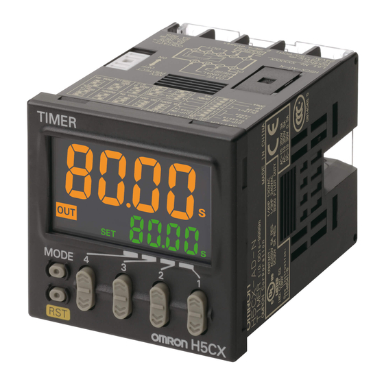
Digital Timer
H5CX
Please read and understand this catalog before purchasing the products. Please consult your OMRON representative if you have any questions
or comments. Refer to Warranty and Application Considerations (page 52), and Safety Precautions (page 47).
DIN 48 ´ 48-mm Multifunction Digital Timer/2-stage Digital Timer
• Highly visible display with backlit negative transmissive LCD.
• Finger-safe terminals (screw terminal block models).
• Complies with IP66, NEMA4, and UL Type 4X (when using the Y92S-29 Waterproof Packing and Y92F-30 Flush Mounting Adapt-
er).
H5CX-A/-L
Multifunction Digital Timer
with 4-digit display
H5CX-A (standard type)
H5CX-L (economy type)
H5CX Series
Contents
Multifunction Digital Timer
H5CX-A/-L........................................................
2-stage Digital Timer
H5CX-B............................................................ 35
Common to All Models
Safety Precautions ........................................... 47
Warranty and Application Considerations ........ 52
H5CX-B
1
2
2-stage Digital Timer
with 6-digit display
H5CX-B
2
H5CX
Digital Timer
1
Advertisement
Chapters
Table of Contents

Related Manuals for Omron H5CX-L


Summary of Contents for Omron H5CX-L
- Page 1 Digital Timer H5CX Please read and understand this catalog before purchasing the products. Please consult your OMRON representative if you have any questions or comments. Refer to Warranty and Application Considerations (page 52), and Safety Precautions (page 47). DIN 48 ´ 48-mm Multifunction Digital Timer/2-stage Digital Timer •...
-
Page 2: Table Of Contents
Multifunction Digital Timer H5CX-A/-L DIN 48 ´ 48-mm Multifunction Digital Timer with a Bright, Easy-to-view, Negative Transmissive LCD. • Programmable PV color to visually alert when output status changes (screw terminal block models). • Intuitive setting enabled using DIP switch (H5CX-A/-A11 mod- els) and ergonomic up/down digit keys. -
Page 3: Model Number Structure
Model Number Structure Model Number Legend H5CX-@@@@-@ 1 2 3 4 1. Type classifier 3. Output type Standard type None: Contact output Economy type Transistor output 2. External connection 4. Supply voltage None: Screw terminals None: 100 to 240 VAC 50/60 Hz 8-pin socket 12 to 24 VDC/24 VAC 50/60 Hz 11-pin socket... -
Page 4: Specifications
Specifications Ratings Item H5CX-A@ H5CX-A11@ H5CX-L8@ Classification Digital timer Rated supply voltage 100 to 240 VAC (50/60 Hz), 24 VAC (50/60 Hz)/12 to 24 VDC (permissible ripple: 20% (p-p) max.) Operating voltage range 85% to 110% rated supply voltage (12 to 24 VDC: 90% to 110%) Power consumption Approx. - Page 5 2. The value is applied for a minimum pulse width of 1 ms. 3. To meet UL listing requirements with H5CX-L8@/-A11@ models, an OMRON P2CF-08-@ or P3G-08 Socket must be mounted on the Timer. Otherwise, H5CX-L8@/-A11@ models are considered to meet UL508 recognition requirements.
- Page 6 Life-test Curve (Reference Values) 1,000 30 VDC L/R=7 ms 250 VDC/3 0 VDC cosφ=1 250 VAC cosφ=0.4 Load current (A) Reference: A maximum current of 0.15 A can be switched at 125 VDC (cos f =1) and a maximum current of 0.1 A can be switched if L/R is 7 ms.
-
Page 7: Connections
Connections Block Diagram (Basic insulation) Power supply Output circuit circuit (See note.) (Basic insulation) Display circuit Internal control Input circuit circuit Key switch circuit Note: Power circuit is not insulated from the input circuit, except for H5CX-A11/-A11S, which have basic insulation. I/O Functions Inputs Start signal... - Page 8 Terminal Arrangement Confirm that the power supply meets specifications before use. H5CX-AS/-ASD H5CX-A/-AD Input use 0 V Unused Input use 0 V Unused Unused Unused Unused Unused Unused Unused Transistor output Contact output (−) (−) The power supply and input circuit are not insulated. The power supply and input circuit are not insulated.
- Page 9 Input Circuits Signal, Reset, and Gate Input +14 V 1 kΩ Internal circuit Note: When using no-voltage input (NPN input). Input Connections The inputs of the H5CX-A@/-A11@ are no-voltage (short-circuit or open) inputs or voltage inputs. The input of the H5CX-L8@ is no-voltage input only. Note: Power circuit is not insulated from the input circuit, except for H5CX-A11/-A11S, which have basic insulation.
- Page 10 Voltage Inputs (PNP Inputs) No-contact Input Contact Input No-contact Input (PNP Transistor) (NPN Transistor) (Connection to NPN open (Connection to PNP open collector output sensor) collector output sensor) Sensor Sensor H5CX-A@ H5CX-A@ H5CX-A@ H5CX-A11@ H5CX-A11@ H5CX-A11@ Operate with relay ON Operate with transistor ON Operate with transistor OFF Voltage Input Signal Levels...
-
Page 11: Nomenclature
Nomenclature Operation Key Indicator Mode Key Reset Indicator (orange) (Changes modes and setting items) Key Protection Indicator (orange) Reset Key (Resets present value and output) Control Output Indicator (orange) Present Value Up Keys 1 to 4 (red or green (programmable) for H5CX-A models, red for H5CX-A11 Down Keys 1 to 4 /-L models) -
Page 12: Dimensions
Dimensions Note: All units are in millimeters unless otherwise indicated. Dimensions without Flush Mounting Adapter H5CX-A/-AS (Flush Mounting Models) 48x48 44.8x44.8 Note: M3.5 terminal screw (effective length: 6 mm) H5CX-AD/-ASD (Flush Mounting Models) 48x48 44.8x44.8 Note: M3.5 terminal screw (effective length: 6 mm) H5CX-A11/-A11S (Flush Mounting/Surface Mounting Models) 14.4 48x48... - Page 13 Dimensions with Flush Mounting Adapter H5CX-A/-AS (Provided with Adapter and Waterproof Packing) Y92S-29 (provided) Panel Waterproof Packing Y92F-30 (provided) Flush Mounting Adapter (51) 98.5 H5CX-AD/-ASD (Provided with Adapter and Waterproof Packing) Y92S-29 (provided) Panel Waterproof Packing Y92F-30 (provided) Flush Mounting Adapter (51) Panel Cutouts Panel cutouts areas...
- Page 14 Dimensions with Front Connecting Socket H5CX- H5CX- A11/- A11D/- A11S A11SD 109.7 100.9 103.2 92.3 P2CF-08-@ P2CF-11-@ P2CF-11-@ Note: These dimensions vary with the kind of DIN track (reference value). Accessories (Order Separately) Note: All units are in millimeters unless otherwise indicated. Track Mounting/Front Connecting Socket Eight, P2CF-08...
- Page 15 Track Mounting/Front Connecting Socket P2CF-11 Eleven, M3.5 x 7.5 sems Terminal Arrangement/ 70 max. 35.4 Internal Connections (Top View) Surface Mounting Holes Two, 4.5 dia. holes Two, 4.5 dia. or two, M4 50 max. 31.2 max. 40±0.2 P2CF-11-E (Finger Safe Terminal Type) Conforming to VDE0106/P100 Eleven, M3.5 x 7.5 sems...
- Page 16 Note: 1. Depending on the operating environment, the condition of Soft Cover Hard Cover resin products may deteriorate, and may shrink or become Y92A-48F1 harder. Therefore, it is recommended that resin products Y92A-48 are replaced regularly. 2. The H5CX’s panel surface is water-resistive (conforming to IP66) and so even if drops of water penetrate the gaps be- tween the keys, there will be no adverse effect on internal circuits.
-
Page 17: Operating Procedures
Operating Procedures Setting Procedure Guide Settings for Timer Operation Use the following settings for all models except the H5CX-L8@. Refer to page 19 for the H5CX-L8@. When Using Basic Functions Only The settings can be performed easily with the DIP switch. Basic Functions For details on the setting methods, refer to page 18. -
Page 18: Operating Procedures (Timer Function)
Operating Procedures (Timer Function) Settings for Basic Functions Settings for basic functions can be performed with just the DIP switch. Be sure to set pin 1 to ON when using the DIP switch. Item Pin 2 Pin 3 Pin 4 Time range DIP switch set- Disabled... - Page 19 Settings for Advanced Functions Settings that cannot be performed with the DIP switch are performed with the operation keys. Power ON For details on operations in run mode, refer to page 21. Note 1. If the mode is switched to the function setting mode during operation, operation will continue.
- Page 20 Explanation of Functions Input Signal Width (iflt) (Setting possible using DIP switch.) Time Range (timr) (Setting possible using DIP switch.) Set the minimum signal input width (20 ms or 1 ms) for signal, reset, and gate inputs. The same setting is used for all external inputs (sig- Set the range to be timed in the range 0.000 s to 9,999 h.
- Page 21 Operation in Run Mode When Output Mode Is Not Z Set each digit for the set value using the corresponding keys. Present value Set value When Output Mode Z Is Selected Set each digit for the ON duty ratio using the corresponding keys.
- Page 22 Timing Charts Timer Operation The gate input is not included in the H5CX-L8@ models. One-shot output Sustained output Either one-shot output or sustained output can be selected. Output mode A: Signal ON delay 1 (Timer resets when power comes ON.) Power Timing starts when the start signal goes ON.
- Page 23 Output mode b: Repeat cycle 1 (Timer resets when power comes ON.) Timing starts when the start signal goes ON. Sustained Power The status of the control output is reversed when time Output is up (OFF at start). While the start signal is ON, the timer starts when the Start signal power comes ON or when the reset input goes OFF.
- Page 24 Output mode d: Signal OFF delay (Timer resets when power comes ON.) The control output is ON when the start signal is ON Power (except when the power is OFF or the reset is ON). The timer is reset when the time is up. Start signal Basic Operation Gate...
- Page 25 Self-diagnostic Function The following displays will appear if an error occurs. Main display Sub-display Error Output status Correction method Set value after reset Not lit Either press the reset key or reset the No change power supply. Not lit Memory error (RAM) Reset the power supply.
-
Page 26: Operating Procedures (Twin Timer Function)
Operating Procedures (Twin Timer Function) Switching from Timer to Twin Timer The H5CX is factory-set for timer operation. To switch to twin timer operation, use the procedure given below. For details, refer to page 32. Power ON Timer/twin timer selection mode Run mode Timer/ twin timer... - Page 27 Settings for Advanced Functions Settings that cannot be performed with the DIP switch are performed with the operation keys. Power ON For details on operations in run mode, refer to page 29. Note 1. If the mode is switched to the function setting mode during operation, operation will continue.
- Page 28 Explanation of Functions OFF Time Range (oftr) (Setting possible using DIP Input Signal Width (iflt) (Setting possible using DIP switch.) switch.) Set the time range for the OFF time in the range 0.000 s to 9,999 h. Set the minimum signal input width (20 ms or 1 ms) for signal, reset, Only settings of type --.-- s (99.99 s), ---.- s (999.9 s), ---- s (9,999 s), and gate inputs.
- Page 29 Operation in Run Mode Set the digits for the OFF set time using the corresponding keys. Present value OFF set time Set the digits for the ON set time using the corresponding keys. Present value ON set time Present Value and OFF Set Time The present value is displayed in the main display and the OFF set time is displayed in the sub-display.
- Page 30 Timing Charts Twin Timer Operation The gate input is not included in the H5CX-L8@ models. Output mode toff: Flicker OFF start Timing starts when the start signal goes ON. Sustained Power The status of the control output is reversed when time Output is up (OFF at start).
-
Page 31: Operation In Timer/Twin Timer Selection Mode
Operation in Timer/Twin Timer Selection Mode Select whether the H5CX is used as a timer or a twin timer in timer/twin timer selection mode. The H5CX is also equipped with a DIP switch monitor function, a convenient function that enables the settings of the DIP switch pins to be confirmed using the front display. Power ON To change the mode to timer/twin timer selection mode, hold down the... -
Page 32: Additional Information
Additional Information Using the Operation Keys Timer Operation Operation stopped Power ON Can be in operation 1 s min. 3 s min. Timer/twin timer selection mode Run mode Function setting mode Timer (Except for Z mode) 1 s min. 3 s min. Timer/twin timer selection Time range PV/SV... - Page 33 List of Settings Fill in your set values in the set value column of the following tables and utilize the tables for quick reference. Timer/Twin Timer Selection Mode Parameter Parameter Setting range Default value Unit Set value name func tim/twin Timer/Twin Tim- er selection on/off...
- Page 34 Settings for Twin Timer Operation Run Mode Parameter name Parameter Setting range Default value Unit Set value 0.00 to 99.99 (Time range: --,--s) 0.00 Present value, OFF set time OFF set time 0.0 to 999.9 (Time range: ---,-s) 0 to 9999 (Time range: ----s) 0:00 to 99:59 (Time range: --min--s) 0:00 min;...
- Page 35 2-stage Digital Timer H5CX-B DIN 48 ´ 48-mm Digital Timer with 6-digit Display and Forecast Output • Times the daily operating hours of machinery and tools, predict- ing and notifying when maintenance is required. • The 2-stage settings and forecast output are ideal for mainte- nance applications.
-
Page 36: Model Number Structure
Model Number Structure Model Number Legend H5CX-BWSD 1 2 3 4 1. Type classifier 3. Output type 6-digit display type Transistor output 2. Stage setting 4. Supply voltage 2-stage setting 12 to 24 VDC Ordering Information List of Models Output type Supply voltage 6-digit display Screw terminals... -
Page 37: Specifications
Specifications Ratings Item H5CX-BWSD Classification Digital timer Rated supply voltage 12 to 24 VDC (permissible ripple: 20% (p-p) max.) Operating voltage range 90% to 110% rated supply voltage Power consumption Approx. 2.3 W at 12 VDC (See note 1.) Mounting method Flush mounting External connections Screw terminals... - Page 38 Characteristics Item H5CX-BWSD Power-ON start: ± 0.02% ± 0.05 s max. Rated against set value Accuracy of operating time and setting error (including Signal start (minimum pulse width of 20 ms): ± 0.01% ± 0.03 s max. Rated against set value temperature and voltage in- Signal start (minimum pulse width of 1 ms): ±...
-
Page 39: Connections
Connections Block Diagram Power supply Output circuit circuit (Basic insulation) Display circuit Internal control Input circuit circuit Key switch circuit I/O Functions Inputs Start signal Starts timing. Reset Resets present value. (The present value returns to 0.) Timing stops and control output turns OFF while reset input is ON. Reset indicator is lit while reset input is ON. - Page 40 Terminal Arrangement Input use 0 V Unused OUT1 OUT2 (−) Note 1. Do not connect unused terminals as relay terminals. 2. The power supply and input circuit are not isolated. 3. Terminals 1 and 6 are connected internally. 4. Terminals 7 and 10 have the same reset function. The same function will be performed whichever terminal is connected. Terminals 7 and 10 are not connected internally, however, so do not use them for cross-over wiring.
- Page 41 Input Connections The inputs of the H5CX-B are no-voltage (short-circuit or open) inputs or voltage inputs. No-voltage Inputs (NPN Inputs) Contact Input Open Collector Voltage Output DC Two-wire Sensor PLC or sensor Sensor Operate with transistor ON Operate with relay ON Operate with transistor ON Operate with transistor ON Applicable Two-wire Sensor...
-
Page 42: Nomenclature
Nomenclature Operation Key Indicator Reset Indicator (orange) Mode Key (Changes setting items) Lit when the reset input or Reset Key is ON. Reset Key Key Protection Indicator (orange) (Resets present value and output) Lit when the Key-protect Switch is Up Keys 1 to 6 Control Output Indicator (orange) Forecast value setting: Sixth digit... -
Page 43: Dimensions
Dimensions Note: All units are in millimeters unless otherwise indicated. Dimensions without Flush Mounting Adapter H5CX-BWSD (Flush Mounting Models) Panel Cutouts Panel cutouts areas 48x48 shown below. (according to DIN43700). 60 min. 44.8x44.8 +0.6 −0 +0.6 −0 Note: M3.5 terminal screw (effective length: 6 mm) 60 min. -
Page 44: Operating Procedures
Operating Procedures Setting Set Values Forecast Value Setting Set values can be set either as offset values (forecast value setting) or absolute values. Set values are factory-set to forecast value set- ting. Example: F-1 Mode Present value Turn ON the power while Set value pressing the Key and... - Page 45 DIP Switch Settings All functions are set using the DIP switch. Item Pin 1 Pin 2 Time range Time range Refer to the table on the right. 0.1 h to 99999.9 h 0.01 s to 9999.99 s Output mode F-1 mode A mode 0 h 00 min 01 s to 99 h 59 min 59 s Input signal width...
- Page 46 Timing Charts A Mode: Signal ON delay (Timer resets when power comes ON.) • Timing starts when the start signal turns ON. Power • While the start signal is ON, the timer starts when the power turns ON or when the reset input turns OFF. •...
- Page 47 Safety Precautions (Common) Note: The following precautions are common for all H5CX models. • Leaving the H5CX with outputs ON at a high temperature for a long CAUTION time may hasten the degradation of internal parts (such as electrolytic capacitors). Therefore, use the product in combination Loose screws may occasionally result in fire or malfunction.
- Page 48 Precautions for Correct Use Response Delay Time When Resetting (Transistor Output) Power Supplies The following table shows the delay from when the reset signal is input until the output is turned OFF. Turn the power ON and OFF using a relay with a rated capacity of 10 A minimum to prevent contact deterioration due to inrush current (Reference value) caused by turning the power ON and OFF.
- Page 49 Safety Precautions (H5CX-A/-L) Precautions for Safe Use CAUTION If the output relay is used beyond its life expectancy, its contacts Usage Precautions may occasionally become fused or there may occasionally be a risk of fire. The life expectancy of the output relay varies considerably according to its usage.
- Page 50 Safety Precautions (H5CX-B) Precautions for Safe Use Changing the Set Value When changing the set value during a timing operation, the output will turn ON if the set value is changed as follows because of the use of a constant read-in system: Forecast Value Setting When the present value ³...
- Page 51 H5CX Digital Timer...
- Page 52 CONTRACT, WARRANTY, NEGLIGENCE, OR STRICT LIABILITY. In no event shall the responsibility of OMRON for any act exceed the individual price of the product on which liability is asserted. IN NO EVENT SHALL OMRON BE RESPONSIBLE FOR WARRANTY, REPAIR, OR OTHER CLAIMS REGARDING THE...