Advertisement
Quick Links
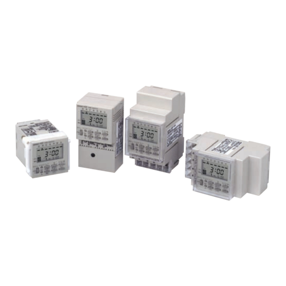
Digital Daily Time Switch
H5F
Daily Time Control with Simple Operations
• Specify the operation days.
(However, you can set only one pattern of operation days
and specified days.)
• Up to 12 ON/OFF operations (24 for pulse-output operation).
• Special holidays can be handled easily with the holiday
setting function.
• Adjustments for sudden schedule changes can be made eas-
ily using output override and automatic return operation.
• The operation program can be checked easily with the pro-
gram check function.
• Enables pulse output operation and summer time setting.
• Incorporates finger-safe terminals.
• Conforms to UL, CSA, and CE marking.
• Meets a variety of mounting requirements: flush mounting,
surface mounting, and DIN track mounting.
Model Number Structure
■ Model Number Legend
H5F-@B
1 2
1. Mounting method
None:
Flush mounting
F:
Surface mounting
K:
Surface mounting/track mounting
2. Language
B:
English
Ordering Information
■ List of Models
Wiring
Screw terminals
■ Accessories (Order Separately)
Soft cover
Hard cover
Flush Mounting Adapter (See note 2.)
Mounting Track
End Plate
Spacer
Note: 1. Supplied with H5F-KB model.
2. Supplied with H5F-B (flush-mounting) model.
Mounting method
Flush mounting
Surface mounting
Surface mounting/track mounting
Name
For H5F-B
For H5F-FB/-KB
50 cm (l) × 7.3 mm (t)
1 m (l) × 7.3 mm (t)
1 m (l) × 16 mm (t)
For the most recent information on models that have been certified for
safety standards, refer to your OMRON website.
H5F-B
H5F-FB
H5F-KB
Y92A-48F1
Y92A-48
Y92A-48E (See note 1.)
Y92F-30
PFP-50N
PFP-100N
PFP-100N2
PFP-M
PFP-S
CSM_H5F_DS_E_3_3
P S
E
Model
Models
1
Advertisement

Related Manuals for Omron H5F-B


Summary of Contents for Omron H5F-B
- Page 1 • Conforms to UL, CSA, and CE marking. For the most recent information on models that have been certified for • Meets a variety of mounting requirements: flush mounting, safety standards, refer to your OMRON website. surface mounting, and DIN track mounting. Model Number Structure ■...
-
Page 2: Specifications
Light gray (Munsell 5Y7/1) Weight H5F-B: approx. 115 g; H5F-KB: approx. 160 g; H5F-FB: approx. 130 g Note: 1. The total error including the repeat accuracy, setting error, variation due to voltage change, and variation due to temperature change is ±0.01%±0.05 s max. -
Page 3: Operation
Connections ■ Terminal Arrangement Flush Mounting Models Surface Mounting Models Surface Mounting/Track Mounting Models H5F-B H5F-FB H5F-KB (Front View) (Front View) (Rear View) Power source TIME SWITCH SU MO TU WE TH 100 to 240 VAC 3 00 5 00... - Page 4 ■ Operation Functions Timer operation (ON/OFF operation) Controls the output according to preset of ON and OFF times • Minimum setting unit: 1 min • Up to 12 ON/OFF operations are possible per day. ON time OFF time Pulse-output operation Output turns ON for a fixed period (pulse width) at the set time.
- Page 5 Nomenclature Front Panel (Actual Size) TIME SWITCH SU MO TU WE TH FR SA A Mode Key POWER B h Key I TMR/ TMR/ MODE / WD C m/ WD Key H Output ON/OFF AUTO SELECT WRITE D Write Key Switch HOLIDAY TEST...
- Page 6 Dimensions Note: All units are in millimeters unless otherwise indicated. H5F-B (provided with Y92F-30 Flush Mounting Adapter) (Flush Mounting) Y92A-48 Hard Cover (sold separately) Panel Cutout Dimensions 63.7 Terminal cover (provided) (according to DIN43700) H5 F TIM E SW ITC H 3 0 0 37.7 44.8...
- Page 7 Soft Cover Hard Cover (provided with H5F-KB) Y92A-48F1 Y92A-48 (for H5F-B) Y92A-48E (for H5F-FB/-KB) Settings can be changed by pressing on the front of the Cover. The settings are harder to change, however, with the Cover mounted. Confirm that this does not hamper operation. Although the Soft Cover provides protection equivalent to IP54F, do not use the Time Switch in locations where it may be directly subject to splashes of oil.
- Page 8 Precautions Refer to Safety Precautions for All Timers. ■ Operating Environment !CAUTION • Do not use the Time Switch in locations where condensation may Do not touch any of the terminals while power is being supplied. Doing occur due to high humidity or where temperature changes are so may result in electric shock.
- Page 9 ■ Precautions for EN61010-1 Conformance The H5F Time Switch conforms to EN61010-1 provided that the fol- lowing conditions are satisfied: Basic insulation is provided between the power supply and output terminals of the H5F. • Output terminals are connected to devices without exposed charged parts.
-
Page 10: Operating Method
Operating Method ■ Operating Method 3. Press the Key. The colon WRITE SU MO TU WE TH FR SA will flash and the clock will start (from 0 s). 4 00 Selecting the Mode All of the modes can be selected using , and MODE HOLIDAY... - Page 11 3. Set the pulse width to 30 s using 5. Press the Key. WRITE SU MO TU WE TH FR SA SU MO TU WE TH FR SA (Repeat steps 2 to 5 to make other Key. (The pulse width m/ WD settings if necessary.) can be set in the range 1 to 59 s or...
- Page 12 Setting Partial Operation on Specified 8. Move the symbol to Saturday SU MO TU WE TH FR SA using the Key. Make the operation day indicator flash by pressing the Key. Move the WRITE The Time Switch can be set to operate according to only some of the present day indicator to Sunday settings on a user-specified day.
- Page 13 Changing Pulse-output Operation Clearing the ON/OFF Settings for Settings Individual Programs Example: Changing the pulse width from 30 s to 20 s Example: Clearing the settings for program 2 1. Enter operation time setting mode 1. Enter operation time setting mode The color indicates flashing The color indicates flashing SU MO TU WE TH FR SA...
- Page 14 Holiday Setting Function Switching between 12-hour (am/pm) and 24-hour Display The following example shows how to stop operation for a certain day in the present week and restore normal operation from the following week using the holiday setting function. Each time the Key is pressed for 2 s min.
- Page 15 2. Return the setting of the output ON/OFF switch from Example 3: Override and automatic return operation Switch starting from a forced OFF while output is ON OFF to AUTO while holding down the Key. WRITE The OFF state will be held from the point at which this (pulse width: 30 min) AUTO operation is performed (indicated by the arrow) until...
-
Page 16: Setting Precautions
■ Setting Examples Example 3: Use the settings given below to turn ON output from 8:00 pm to 7:00 am from Monday As shown in the following examples, continuous operation for more to Thursday and from 8:00 pm on Friday right than 24 hours is possible by combining two or more settings. - Page 17 (a) Exclusive Warranty. Omron’s exclusive warranty is that the Products will be free from defects in materials and workmanship for a period of twelve months from the date of sale by Omron (or such other period expressed in writing by Omron). Omron disclaims all other warranties, express or implied.