
Related Manuals for Sega WaveRunner


Summary of Contents for Sega WaveRunner
- Page 1 1st PRINTING NOV 01 OWNER’S MANUAL SEGA ENTERPRISES, INC. USA MANUAL NO. 999-1375...
- Page 2 VISIT OUR WEBSITE!
- Page 3 BEFORE USING THE PRODUCT, To maintain the safety: To ensure the safe usage of the product, be sure to read the following before using the product. The following instructions are intended for the users, operators and the personnel in charge of the operation of the product. After carefully reading and sufficiently understanding the warning displays and cautions, handle the product appropriately.
- Page 4 SEGA shall not be held responsible for any accidents, compensation for damage to a third party, resulting from the specifications not designated by SEGA.
-
Page 5: Table Of Contents
TABLE OF CONTENTS BEFORE USING THE PRODUCT, BE SURE TO READ THE FOLLOWING: TABLE OF CONTENTS INTRODUCTION OF THE OWNER'S MANUAL 1. HANDLING PRECAUTIONS ...1 2. PRECAUTIONS CONCERNING INSTALLATION LOCATION ...3 3. OPERATION ...5 4. NAME OF PARTS ...10 5. ACCESSORIES ...11 6. -
Page 6: Introduction Of The Owner's Manual
Indicates that mishandling the product by disregarding this display can cause the product's intrinsic performance not to be obtained, resulting in malfunctioning. SEGA ENTERPRISES, INC. (U.S.A.)/CUSTOMER SERVICE 45133 Industrial Drive, Fremont, California 94538, U.S.A. Phone:... - Page 7 DEFINITION OF LOCATION'S MAINTENANCE MAN AND SERVICEMAN Non-technical personnel who do not have technical knowledge and expertise should refrain from performing such work that this manual requires the location's maintenance man or a serviceman to carry out, or work which is not explained in this manual.
-
Page 8: General Precautions
General Precautions Follow Instructions: All operating and use instructions should be followed. Attachments: Do not use attachments not recommended by the product manufacturer as they may cause hazards. Accessories: Do not place this product on an unstable cart, stand, tripod, bracket, or table. The product may fall, causing serious injury to a child or adult, and serious damage to the product. - Page 9 Safety Check: Upon completion of any service or repairs to this product, ask the service technician to perform safety checks to determine that the product is in proper operating condition. Heat: The product should be situated away from heat sources such as radiators, heat registers, stoves, or other prod- ucts (including amplifiers) that produce heat.
-
Page 10: Handling Precautions
• SEGA shall not be held responsible for damage, compensation for damage to a third party, caused by specification changes not designated by SEGA. - Page 11 Some parts are the ones designed and manufactured not specifically for this game machine. The manufacturers may discontinue, or change the specifications of, such general-purpose parts. If this is the case, Sega cannot repair or replace a failed game machine whether or not a warranty period has expired.
-
Page 12: Precautions Concerning Installation Location
2. PRECAUTIONS CONCERNING INSTALLATION LOCATION This product is an indoor game machine. Do not install it outside. Even indoors, avoid installing in places mentioned below so as not to cause a fire, electric shock, injury and or malfunctioning. Places subject to rain or water leakage, or places subject to high humidity in the proximity of an indoor swimming pool and or shower, etc. - Page 13 To avoid machine malfunctioning and a fire, do not place any obstacles near the ventilation opening. SEGA shall not be held responsible for damage, compensation for damage to a third party, resulting from the failure to observe this instruction.
-
Page 14: Operation
3. OPERATION PRECAUTIONS TO BE HEEDED BEFORE STARTING THE OPERATION To avoid injury and trouble, be sure to constantly give careful attention to the behavior and manner of the visitors and players. In order to avoid accidents, check the following before starting the operation: To ensure maximum safety for the players and the customers, ensure that where the product is operated has sufficient lighting to allow any warnings to be read. - Page 15 Do not put any heavy item on this product. Placing any heavy item on the product can cause a falling down accident or parts damage. Do not climb on the product. Climbing on the product can cause falling down accidents. To check the top portion of the product, use a step. To avoid electric shock, check to see if door &...
- Page 16 PRECAUTIONS TO BE HEEDED DURING OPERATION (PAYING ATTENTION TO CUSTOMERS) To avoid injury and trouble, be sure to constantly give careful attention to the behavior and manner of the visitors and players. To avoid injury and accidents, those who fall under the following categories are not allowed to play the game.
- Page 17 To avoid injury and parts damage, instruct players that only up to two persons are allowed to ride. To avoid injury resulting from falling down, and electric shock due to spilled drinks, instruct the player not to place heavy items or drinks on the product.
- Page 18 Immediately stop such violent acts as hitting and kicking the product. Such violent acts can cause parts damage or falling down, resulting in injury due to fragments and falling down. When riding in tandem, firmly hold on to the front player.
-
Page 19: Name Of Parts
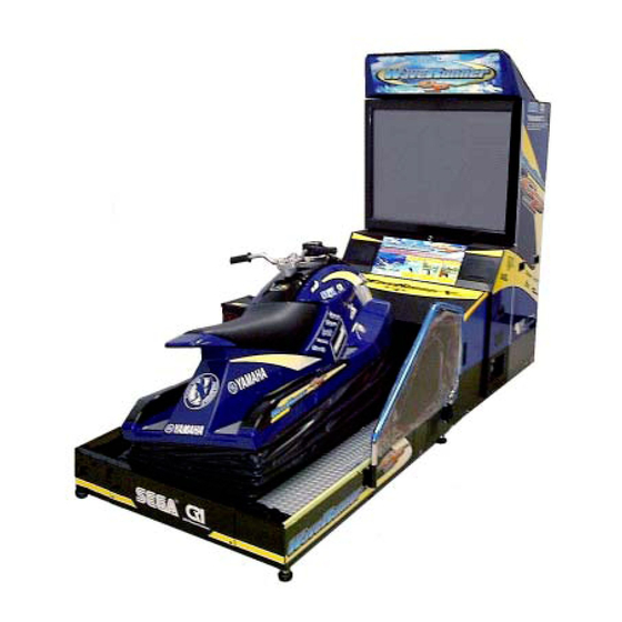
4. NAME OF PARTS COMPRESSOR BOX ASSY WIRE TUBE TABLE 4 Dimensions and Weights Items 44.9in [1,140mm] BILLBOARD 45.4in [1,152mm] FRONT CABINET 45.3in [1,150mm] REAR CABINET 56.5in [1,435mm] COMPRESSOR BOX 43.9in [1,115mm] www.seuservice.com BILLBOARD PTV 50 TYPE PROJECTOR FRONT CABINET C O I N C H U T E CASHBOX DOOR... -
Page 20: Accessories
5. ACCESSORIES When transporting the machine, make sure that the following parts are supplied. TABLE 5 a ACCESSORIES DESCRIPTION OWNERS MANUAL Part No. (Qty.) 420-6659-01 (1) Note Figures If Part No. has no description, the Number has not been registered or can not be registered. Such a part may not be obtainable even if the customer desires to purchase it. -
Page 21: Spare, See Section 17
FUSE 7A 514-5036-7000 (1) Spare, see Section 17. www.seuservice.com CARTON BOX 601-10532 (1) Used for transporting the GameBoard. See FIG 5. - Page 22 HOW TO USE THE CARTON BOX When requesting for the replacement/repair of this product's Game Board (NAOMI BOARD), follow the instructions below. Transporting the Game Board in an undesignated status is unacceptable. An erroneous handling can cause parts damage. • Put the Game Board in the Carton Box together with the Shield Case. Do not unnecessarily disassemble nor remove parts.
- Page 23 The following Table 5b lists the parts that had been separately packed when the product was shipped from the factory but are necessary when you use the product. These parts will be mounted on the product when installing and assembling it. TABLE 5 b AC Cable (Power Cord) 600-6729...
- Page 24 ASSY FIBER CABLE 600-6275-0700 (2) NUMBER STICKER WRG-0003 (1) 1 set of every two sheet sticker, the number 2, 3 and 4. www.seuservice.com...
-
Page 25: Assembling And Installation
6. ASSEMBLING AND INSTALLATION Perform assembly work by following the procedure herein stated. Failing to comply with the instructions can cause electric shock hazard. Perform assembling as per this manual. Since this is a complex machine, erroneous assembling can cause an electric shock, machine damage and or not functioning as per specified performance. -
Page 26: Key Master
Tools required for the work Phillips type screwdriver (for M4, M5 screw) 24mm WRENCH (for M16 hexagon bolt) ASSEMBLING THE PTV Fix the two mask holders onto the PTV top panel each with the 2 countersunk-head screws. Insert the TV mask from the underside as illustrated below, and secure with a total of 6 screws. Fix two PTV holders onto the PTV front side each with the 2 screws. - Page 27 Mount the PTV onto the Front Cabinet. When performing this work, be sure to use 4 or more persons. Fix between the PTV and the Front Cabinet on the Cabinet's both sides with 2 screws for each. While supporting the Billboard by 2 persons, another person using a step is to connect the Billboard wire connector into the terminal board of the PTV top panel.
- Page 28 Insert the Billboard into the holder bracket, fix to PTV with the 2 screws. Remove the 2 truss screws; dismount the lower lid form the Front Cabinet's face side. TRUSS SCREW (black) M4 X 25 Connect two wire-connectors inside the Front Cabinet into the PTV connector panel. The connection angle is fixed.
- Page 29 WIRING CONNECTIONS BETWEEN THE CABINETS Perform the cabinet-to-cabinet wiring. With the ASSY Wire Tube, which installed to the Rear Cabinet at the time of shipment, connect between the Front Cabinet and the Rear Cabinet. Remove the fixed 4 truss screws and remove the front cabinet side Tube Bracket of the ASSY Wire Tube from the Rear Cabinet.
- Page 30 Install the Tube Bracket to the Front Cabinet, and fix it with the 4 truss screws by using care so as not to damage the wiring. TRUSS SCREW (4),black M5 X 20 PHOTO 6. 2 c www.seuservice.com...
- Page 31 SECURING IN PLACE (ADJUSTER ADJUSTMENT) Make sure that all of the adjusters are in contact with the floor. If they are not, the cabinet can move and cause an accident. This product has 8 casters (4 for FRONT CABINET, 4 for REAR CABINET) and 8 Adjusters (4 for FRONT CABINET, 4 for REAR CABINET).
- Page 32 REMOVING THE SHIPPING BRACKET Before turning the power on, be sure to remove the Sipping Brackets. Turning power on without removing the Sipping Brackets may cause the parts damage. Keep the Sipping Brackets carefully. Removing the product without the Sipping Brackets can cause parts damage. At the time of shipment, the Shipping Brackets are secured to rear both sides of the Ride.
- Page 33 POWER SUPPLY, AND EARTH CONNECTION Be sure to independently use the power supply socket outlet equipped with an Earth Leakage Breaker. Using a power supply without an Earth Leakage Breaker can cause a fire when electric leakage occurs. Ensure that the "accurately grounded indoor earth terminal" and the earth wire cable are available (except in the case where a power cord plug with earth is used).
- Page 34 Connect one end of the earth wire to the AC Unit earth terminal, and the other end to the indoor earth terminal. The AC Unit earth terminal has a Bolt and Nut combination. Take off the Nut, pass the end of earth wire through the Bolt, and fasten the Nut.
- Page 35 TURNING POWER ON When the power is turned on, the ride portion moves. To prevent injury, first check for safety in the periphery of the ride and then turn power on. If ERROR is displayed in the ADVERTISE mode, do not operate the machine.
- Page 36 ASSEMBLY CHECK In the TEST MODE, ascertain that the assembly has been made correctly and IC BD is satisfactory (refer to Section 9). In the test mode, perform the following test: ( 1 ) MEMORY TEST RAM TEST IC29 GOOD IC35 GOOD IC09 GOOD IC10 GOOD IC11 GOOD IC12 GOOD...
- Page 37 ( 3 ) SOUND TEST SOUND TEST RIGHT SPEAKER LEFT SPEAKER -> EXIT SELECT WITH SERVICE BUTTON PRESS TEST BUTTON ( 4 ) INPUT TEST INPUT TEST HANDLE BAR ROLL THROTTLE LEVER PITCH START VIEW SAFETY SENSOR SERVICE TEST PRESS TEST AND SERVICE BUTTON TO EXIT ( 5 ) OUTPUT TEST OUTPUT TEST >...
-
Page 38: Precautions To Be Heeded When Moving The Machine
7. PRECAUTIONS TO BE HEEDED WHEN MOVING THE MACHINE When moving the machine, be sure to pull out the plug from the power supply. Moving the machine with the plug as is inserted can cause the power cord to be damaged, resulting in a fire and or electric shock. When moving the machine on the floor, retract the Adjusters and ensure that Casters make contact with the floor. - Page 39 When transporting the product in places with steps or step-like differences in grade, disassemble into each unit before transporting. FIG. 7 b www.seuservice.com...
-
Page 40: Contents Of Game
8. CONTENTS OF GAME The following explanations apply to the case the product is functioning satisfactory. Should there be any moves different from the following contents, some sort of faults may have occurred. Immediately look into the cause of the fault and eliminate the cause therefore to ensure satisfactory operation. - Page 41 Features of the WaveRunner GP It provides several marine scenes where a cruising course appearance varies from play to play. The WaveRunner GP game features: • Effects of Stern Wave A stern wave is the wave produced on the wake of a boat. If your boat runs on the stern waves produced by another boat, it may jump unexpectedly, reduce its speed, or meet any other navigating difficulty.
- Page 42 • The system provides three courses: NOVICE, INTERMEDIATE, and EXPERT. These are displayed on the upper part of the screen. The selected course is highlighted. To migrate from one course to another, turn the handlebars leftwards or rightwards. To decide a course, squeeze the throttle lever.
- Page 43 • When your boat runs on the stern waves, the speed-down gauge is undimmed and its triangle becomes filled with shade. If you keep your boat running on the stern waves, the triangle is shaded more and more. When the triangle is fully shaded, a warning message "Get out of the wake!" appears on the screen.
- Page 44 Outline of the Courses Three cruising courses are provided as below. Note that they are different from each other not only in the difficulty level but also in the appearance and device. • Novice Course This course gives the image of a tropical island against a blue sky where the hot sun grills white beaches.
-
Page 45: Explanation Of Test And Data Display
9. EXPLANATION OF TEST AND DATA DISPLAY By operating the switch unit, periodically perform the tests and data check. When installing the machine initially or collecting cash, or when the machine does not function correctly, perform checking in accordance with the explanations given in this section. The following shows tests and modes that should be utilized as applicable. - Page 46 TABLE 10 EXPLANATION OF TEST MODE ITEMS When the machine is installed, perform the following: INSTALLATION OF MACHINE 1. Check to see that each setting is as per standard setting made at the time of shipment. 2. In the INPUT TEST mode, check such input devices as each SW, V.R., etc.
-
Page 47: Switch Unit And Coin Meter
9 - 1 SWITCH UNIT AND COIN METER Do not touch places other than those specified. Touching places not specified can cause an electric shock or short circuit accident. Adjust to the optimum sound volume by considering the environmental requirements of the installation location. If the COIN METER and the game board are electrically disconnected, game play is not possible. -
Page 48: System Test Mode
9 - 2 SYSTEM TEST MODE The contents of settings changed in the TEST mode are stored when the test mode is finished from EXIT in the menu mode. If the power is turned off before the TEST mode is finished, the contents of setting change become ineffective. -
Page 49: Game Test Mode
9 - 3 GAME TEST MODE As soon as it enters the Game Test mode, the Ride starts moving. Before entering the Game Test Mode, be sure to keep away a person(s) from the Ride. Since the Ride moves momentarily, it may cause accidents. The new settings will not take effect until the Game Test Mode is exited. - Page 50 INPUT TEST When INPUT TEST is selected, the following screen appears on the monitor. The screen allows the status of each SW and the value of each V.R. of the cabinet to be viewed. On this screen, periodically check the status of each switch & V.R. INPUT TEST HANDLE BAR ROLL...
- Page 51 OUTPUT TEST The OUTPUT TEST allows the function of each lamp to be checked. OUTPUT TEST > START LAMP VIEW LAMP EXIT SELECT WITH SERVICE BUTTON AND PRESS TEST BUTTON FIG. 9. 3 c OUTPUT TEST Screen TEST PROCEDURE Press the SERVICE Button to bring the arrow to the lamp item to be tested. Pressing the TEST Button causes "ON"...
- Page 52 GAME ASSIGNMENTS Selecting the GAME ASSIGNMENTS in the menu mode causes the present game setting to be displayed and also the game setting changes can be made. Each item displays the following content. If the COMMUNICATION MODE is set to NO LINK, the items HANDICAP and CABINET ID will not appear.
- Page 53 VOLUME SETTING In this setting item, each V. R. value of the Handlebars, Roll, and Throttle can be set. Performing settings while riding on the Ride is dangerous as the Ride moves. Use the Start button instead of Test button, and the View button instead of Service button.
- Page 54 (1) HANDLE BAR VOLUME SETTING HANDLE BAR VOLUME SETTING NEUTRAL > EXIT WITHOUT SAVE EXIT WITH SAVE SELECT WITH SERVICE BUTTON AND PRESS TEST BUTTON FIG. 9. 3 e b HANDLE BAR VOLUME SETTING Screen SETTING PROCEDURE In the V. R. setting menu screen, press the SERVICE Button to bring the arrow to HANDLE BAR.
- Page 55 (2) ROLL VOLUME SETTING ROLL VOLUME SETTING NEUTRAL > EXIT WITHOUT SAVE EXIT WITH SAVE SELECT WITH SERVICE BUTTON AND PRESS TEST BUTTON FIG. 9. 3 e c ROLL VOLUME SETTING Screen SETTING PROCEDURE In the Volume Setting Menu mode, press the SERVICE Button to bring the arrow to ROLL. Press the TEST Button to have the ROLL VOLUME setting screen appear on the screen.
- Page 56 (3) THROTTLE LEVER VOLUME SETTING THROTTLE LEVER VOLUME SETTING > EXIT WITHOUT SAVE EXIT WITH SAVE SELECT WITH SERVICE BUTTON AND PRESS TEST BUTTON FIG. 9. 3 e d THROTTLE LEVER VOLUME SETTING Screen SETTING PROCEDURE In the Volume Setting Menu, press the SERVICE Button and bring the arrow to THROTTLE LEVER.
- Page 57 VALVE TEST This test allows the functioning of each Air Valve, Limit SW and Volume to be checked. Performing settings while riding on the Ride is dangerous as the Ride moves. Use the Start button instead of Test button, and the View button instead of Service button.
- Page 58 (1) PITCH VALVE & ETR CHECK PITCH VALVE & ETR CHECK PITCH VALVE UP VALVE ETR UP VALVE DOWN VALVE ETR DOWN VALVE ON PITCH ETR UP LIMIT SW DOWN LIMIT SW PITCH VOLUME PRESS TEST BUTTON TO EXIT FIG. 9. 3 f b PITCH VALVE & ETR CHECK Screen TEST PROCEDURE In the VALVE TEST MENU, press the SERVICE Button and bring the arrow to PITCH VALVE &...
- Page 59 (2) ROLL VALVE & ETR CHECK ROLL VALVE & ETR CHECK ROLL VALVE RIGHT VALVE LEFT VALVE ROLL ETR ROLL VOLUME PRESS TEST BUTTON TO EXIT FIG. 9. 3 f c ROLL VALVE & ETR CHECK Screen TEST PROCEDURE In the VALVE TEST MENU, press the SERVICE Button and bring the arrow to ROLL VALVE &...
- Page 60 WIRING TEST Selecting WIRING TEST allows the communication between GAME BD and DRIVE BD to be checked automatically. If the communication is satisfactorily conducted, "OK" is displayed and if any irregularity is found, "ERROR" will be displayed. : ( f 0 ——> 1 1 1 1 1 1 1 0 ) : ( f 1 ——>...
- Page 61 0D 2H 11M 11S 0D 2H 4M 2S 0D 0H 7M 9S 0H 1M 23S 0H 3M 47S 0H 0M 2S Number of games played. Total energized time. Total playtime of one player game only. Total playtime of communication game play.
- Page 62 (1) PLAY TIME HISTOGRAM The time that players have been timeout is displayed in graph. It's a total of 2 screens. BOOKKEEPING 2/12 PLAY TIME HISTOGRAM 1/2 0M00S ~ 0M09S 0M10S ~ 0M19S 0M20S ~ 0M29S 0M30S ~ 0M39S 0M40S ~ 0M49S 0M50S ~ 0M59S 1M00S ~ 1M09S 1M10S ~ 1M19S...
- Page 63 (2) CLEAR TIME HISTOGRAM The clear time of the player, which has made a goal, is displayed in graph. Screens are two screens in NOVICE, INTERMEDIATE and EXPERT, respectively. So it's a total of 6 screens. BOOKKEEPING 4/12 CLEAR TIME HISTOGRAM 1/2 NOVICE 0M00S ~ 0M09S 0M10S ~ 0M19S...
- Page 64 (3) Detailed data of each course Allows for checking the detailed data of each course; NOVICE, INTERMEDIATE and EXPERT. It's a total of 3 screens on each course 1 screen. BOOKKEEPING 10/12 NOVICE CHECK1 CHECK2 CHECK3 CHECK4 CHECK5 CHECK6 PRESS TEST BUTTON TO CONTINUE BOOKKEEPING 11/12 INTERMEDIATE CHECK1...
- Page 65 BACKUP DATA CLEAR Clears the contents of BOOKKEEPING. When clearing the data, use the SERVICE Button to bring the arrow to "YES (CLEAR)" and press the TEST Button. When clearing is finished, "COMPLETED" is displayed. Press the TEST Button again to return to the Game Test Menu screen.
-
Page 66: Air Drive
10. AIR DRIVE In order to prevent an electric shock and short circuit, be sure to turn power off before performing work by touching the interior parts of the product. Be careful so as not to damage wirings. Damaged wiring can cause an electric shock or short circuit accident. -
Page 67: Overview Of Air Drive System
10 - 1 OVERVIEW OF AIR DRIVE SYSTEM This product uses the compressor. Be sure to turn off the main switch of the AC Unit and start working after checking that the compressor motor has stopped. COMPRESSOR UNIT TANK UNIT CIRCUIT PROTECTOR POWER COMPRESSOR UNIT / TANK UNIT... -
Page 68: Dewatering From The Air Filter
10 - 2 DEWATERING FROM THE AIR FILTER Remove the Rear Lid of the Mechanism Base to have the water tank appear in the inner portion on the right-hand side. Although the Air Drive Mechanism of the product automatically dewaters the water from inside the Air Filter, dispose the water from inside the Air Filter by periodically dewatering (every day in the period of high humidity). -
Page 69: Dewatering From The Air Tank
10 - 3 DEWATERING FROM THE AIR TANK Water accumulated in the tank increases the load on the Compressor, which may cause malfunctioning. The Tank should be dewatered at least once a week. Since the oilless compressor is used for this machine, the drain water can be discharged into a sewer system. Turn the main switch of the AC Unit off. -
Page 70: Regulator
10 - 4 REGULATOR The compressed air (primary side) in the air tank is governed to preset pressures by regulators before the air pressure is sent to the cylinders. Check set pressure every 2 months. Remove Lid Left from the Mechanism Base (refer to 11-1) to have the Regulator Unit appear, and check the pressure... -
Page 71: Air Cleaner
10 - 5 AIR CLEANER The Compressor for this machine is the oilless type and so oil replenishment is not necessary. However, if the Air Cleaner for protecting the Compressor becomes dirty, the Compressor's operation efficiency will decrease, and this may cause malfunctioning. Two spare Air Cleaners are available. -
Page 72: Maintenance Of Mechanism Unit
11. MAINTENANCE OF MECHANISM UNIT In order to prevent an electric shock and short circuit, be sure to turn power off before performing work by touching the interior parts of the product. Be careful so as not to damage wirings. Damaged wiring can cause an electric shock or short circuit accident. -
Page 73: Remove The Lid & The Bellows Before Sarting Maintenance Work
11 - 1 REMOVE THE LID & THE BELLOWS BEFORE SARTING MAINTENANCE WORK Turn the main switch of the AC Unit off. Take out the 5 screws to remove the Rear Lid. (See 10 - 2.) There are 2 Air Cocks inside the Rear Lid. Close the Main Cock on the left side by turning 90 degrees. - Page 74 Take out the 3 truss screws. (Photo 11.1b) TRUSS SCREW (3),black M5 X 12 Remove Step L slowly. Use care when removing the Step L so as not to damage the wiring inside the Lid. Removing the Step L, the Regulator is appeared. (Photo 11.1c) Pull off the 2 Connectors.
- Page 75 Take out the 3 truss screws to remove Sash R (L type fitting). (Photo 11.1d) Take out the 3 truss screws. (Photo 11.1e) www.seuservice.com TRUSS SCREW (3) M4 X 12,chrome plated SASH R PHOTO 11. 1 d PHOTO 11. 1 e TRUSS SCREW (3),black M5 X 12...
- Page 76 Remove Step R slowly. Use care when removing the Step R so as not to damage the wiring inside the lid. (Photo 11.1f) Pull out the 2 Connectors. (Photo 11.1g) PHOTO 11. 1 f Take out the 2 truss screws to remove the Bellows Bracket A on both sides ahead of the Ride. (Photo 11.1h) TRUSS SCREW (2),black M5 X 12...
- Page 77 Take out the 2 truss screws to remove the Bellows Bracket Front. (Photo 11.1i) www.seuservice.com TRUSS SCREW (2),black M4 X 12 PHOTO 11. 1 i...
-
Page 78: Greasing And Retightening The Bolts
11 - 2 GREASING AND RETIGHTENING THE BOLTS Be sure to use the designated grease. Using undesignated grease can cause parts damage. Once every 6 months, apply greasing to (Part No. 090 - 0025). Apply Spray Greasing to the Rod End and Bearing from the Grease Nipple. - Page 79 CRANK PORTION BEARING (BOTH SIDES) UPPER PART OF LINK ROD END UPPER PART OF REAR CYLINDER ROD END www.seuservice.com LOWER PART OF LINK & LOWER PART OF REAR CYLINDER BEARING ROD END FRONT CYLINDER PORTION ROD END PITCH VOLUME PORTION GEAR PORTION ROD END of CYLINDER PHOTO 11.
-
Page 80: Adjustment And Replacement Of Pitch Volume
11 - 3 ADJUSTMENT AND REPLACEMENT OF PITCH VOLUME During game, in the cases where the vertical movements of the Ride is irregular or the Volume indicates abnormal values, Pitch Volume Gear mesh may be wrong, or Volume malfunctioning may be the cause. Make adjustments or replace as per the following procedure: Turn the main switch of the AC Unit off. -
Page 81: Remove The Inclination Sensor
11 - 4 REMOVE THE INCLINATION SENSOR The Inclination Sensor detects the inclination of right and left of the Ride. Malfunctioning the Ride toward right-and-left direction can cause a failure of the Inclination Sensor. Replace the Sensor, which located in the bottom behind the Ride, in the following procedure. Turn the main switch of the AC Unit off. - Page 82 Take out the 2 screws and remove the Sensor from the bracket to replace it. INCLINATION SENSOR 370-5130 SCREW (2) M3 X 8 After the replacement, be sure to perform the Roll Volume Setting in the Test Mode (see 9-3 e). PHOTO 11.
-
Page 83: Handle Mechanism
12. HANDLE MECHANISM Before starting to work, ensure that the Power SW is OFF. Failure to observe this can cause electric shock or short circuit. Use care so as not to damage wirings. Damaged wiring can cause electric shock or short circuit. Do not touch undesignated places. - Page 84 Take out a total of 4 Truss Screws to remove ACCEL. COVER A. Take out 2 Truss Screws to remove the VR Cover. Loosen the 2 Nuts which secure the Volume Bracket to move the Volume Bracket. (FIG. 12. 1). VOLUME220-5373 or 220-5484 ACCEL.
- Page 85 Moving the Volume Bracket causes Adjust Gear mesh to be disengaged. Adjust gear mesh and tighten the 2 Nuts. Grip the Throttle Lever and check to ensure that the V. R. value variations are within the rotatable range of the Volume Shaft. After finishing adjustments, be sure to perform Throttle Volume setting on the Volume Setting screen in the Test mode (see 9 - 3e).
-
Page 86: Adjusting Or Replacing The Handle V.r
12 - 2 ADJUSTING OR REPLACING THE HANDLE V.R. Adjust or replace the Handle Volume in the following procedure. This work requires a Phillips screwdriver for M5 screws and a short Phillips screwdriver for M4 screws. Take out the 3 fixed truss screws and remove the cover of one side so as not to put the power excessively. - Page 87 Loosen the 2 screws that secure the V.R. Bracket to move the V.R. Bracket. Move the V. R. Bracket to disengage the Adjust Gear mesh and move the V.R. shaft so that the cut part of the shaft may turn to the opposite side of the Adjuster Gear as shown. Engage the gear and tighten the 2 screws.
-
Page 88: Greasing
12 - 3 GREASING Be sure to use the designated grease. Using undesignated grease can cause parts damage. Once every 3 months, apply greasing to the following portions. For spray grease, use GREASE MATE (PART No. 090-0066). Gear mesh portion Torsion Spring portion Gear mesh portion PHOTO 12. -
Page 89: Coin Selector
13. COIN SELECTOR HANDLING THE COIN JAM If the coin is not rejected when the REJECT button is pressed, open the coin chute door and open the selector gate. After removing the jammed coin, put a normal coin in and check to see that the selector correctly functions. - Page 90 www.seuservice.com...
- Page 91 www.seuservice.com...
- Page 92 OPTIONAL DOLLAR BILL ACCEPTOR THE COIN DOOR ASSEMBLY USED ON WAVERUNNER GP COMES EQUIPPED TO ACCEPT A DOLLAR BILL ACCEPTOR. ALL NEEDED WIRING CONNECTIONS ARE CONVIENENTLY LOCATED INSIDE THE GAME FOR THIS APPLICATION. THE COIN DOOR CAN ACCCOMMODATE THE FOLLOWING...
-
Page 93: Projector
14. PROJECTOR Since the Projector has been adjusted at the time of shipment, avoid making further adjustments without good reason. The Projector is subject to color deviation due to Convergence deviation caused by the geomagnetism at the installation location and peripheral magnetic field. After the installation of machine, and before commencing operation, check for Convergence deviation and if deviated, make adjustments. -
Page 94: Adjustment Of Toshiba Projector
14 - 2 ADJUSTMENT OF TOSHIBA PROJECTOR SETTING THE INTERFACE In this product, set to INPUT LEVEL: 0.7V and IMPEDANCE: 75 . Failure to observe this can cause CRT membrane to burn or Shutdown device to function resulting in power off. The Projector's Connector Panel contains the Interface setting SW. - Page 95 AUTOMATIC COLOR MATCHING The Projector may be subject to color deviations affected by earth magnetism, the building steel frames, etc. When the Projector is initially installed or the Projector's installation position is changed, have the color matching performed automatically. TEST MODE WRITING PIC-ADJ...
- Page 96 ADJUSTING THE ON-SCREEN CONTRAST Although the on-screen picture quality has been adjusted at the time of shipment from the factory, the on-screen contrast can be readjusted if desired. When the Game Board is replaced, readjustment may be necessary. Changing the CONTRAST causes the light and shade of the on-screen images to be changed.
- Page 97 ADJUSTING THE SCREEN BRIGHTNESS Although the on-screen picture quality has been adjusted at the time of shipment from the factory, readjustment can be made if desired. When the Game Board is replaced, readjustment may be necessary. Changing the BRIGHTNESS causes the brightness of the on-screen images of black portions to be changed.
- Page 98 ADJUSTING THE ON-SCREEN DISPLAY POSITION Although the on-screen display position (H. POSI, V. POSI) has been adjusted at the time of shipment from the factory, readjustment can be made if desired. When the Game Board is replaced, readjustments may be necessary. PIC-ADJ TEST MODE...
- Page 99 ADJUSTING THE SCREEN SIZE Although the on-screen size (H. SIZE, V. SIZE) has been adjusted at the time of shipment from the factory, readjustment can be made if desired. When the Game Board is replaced, readjustments may be necessary. PIC-ADJ TEST MODE WRITING...
- Page 100 STOP IMPORTANT! ADJUST MODE SUB VSIZE SUB HSIZE SUB BRIGHT EXIT www.seuservice.com...
-
Page 101: Test Mode Writing
STATIC CONVERGENCE ADJUSTMENT In the static convergence adjustment, each of red and blue images is comprehensively moved to and superimposed on the green color. If automatic color matching function is not sufficiently satisfactory, perform this adjustment. Be sure to perform automatic color matching before starting the above adjustment. - Page 102 POINT CONVERGENCE ADJUSTMENT In the POINT CONVERGENCE adjustment, each of red, green and blue images is partially moved for color matching. The adjustment may be necessary when the Game Board is replaced or changed, or screen size is changed. Be sure to perform automatic color matching before starting the adjustment.
- Page 103 LINE CONVERGENCE ADJUSTMENT In the LINE CONVERGENCE ADJUSTMENT, the adjustment point of the column line (verti- cal) or row line (horizontal) is comprehensively moved for color matching. It is convenient to utilize this adjustment when the color of the column line or row line is uniformly deviated. TEST MODE WRITING...
-
Page 104: Replacement Of Fluorescent Lamp
15. REPLACEMENT OF FLUORESCENT LAMP When performing the work, be sure to turn power off. Working with power on can cause an electric shock or short circuit accident. The Fluorescent Lamp, when it gets hot, can cause burns. Be very careful when replacing the Fluorescent Lamp. -
Page 105: Periodic Inspection Table
16. PERIODIC INSPECTION TABLE The Air Compressor employed in this product drives the Ride during game. The items listed below require periodic check and maintenance to retain the performance of this machine and to ensure safe business operation. Be sure to check once a year to see if Power Cords are damaged, the plug is securely inserted, dust is accumulated between the Socket Outlet and the Power Plug, etc. -
Page 106: Troubleshooting
17. TROUBLESHOOTING 17 - 1 TROUBLESHOOTING In order to prevent electric shock and short circuit, be sure to turn power off before performing work. Be careful so as not to damage wirings. Damaged wiring can cause electric shock or short circuit. After removing the cause of the functioning of the Circuit Protector, reinstate the Circuit Protector. - Page 107 TABLE 17 b PROBLEMS During game, the Ride does Deviation of Handle Volume. not turn when the Handlebars are turned. Malfunctioning of Handle Volume. When gripping the Throttle Deviation of Throttle Volume. Lever, the Ride does not advance. Malfunctioning of Throttle Volume.
- Page 108 CIRCUIT PROTECTOR and FUSE REPLACEMENT In case fuse replacements other than those stated in this manual are necessary, contact where you purchased the product from for inquiries regarding this matter. Fuse replacements other than those specified can cause accidents and are strictly forbidden.
- Page 109 AIR DAMPER ADJUSTMENT In this machine, the Cylinders are equipped with air dampers to soften the impact created by the Ride movements. If the Cylinder's amplitude of vibration or the impact is excessive, adjust the air dampers in the following procedure. After turning the power off, close the Main Cock to start working.
-
Page 110: Error Message
17 - 2 ERROR MESSAGE This work should be performed by the Location's Maintenance Man or Serviceman. Performing work by non-technical personnel can cause accidents. Should any errors other than listed by this manual or by NAOMI Service Manual occur, contact where the product was purchased from or an office described in this manual. - Page 111 DISPLAY CAUSE COUNTERMEASURES DISPLAY CAUSE COUNTERMEASURES DISPLAY CAUSE COUNTERMEASURES DISPLAY CAUSE COUNTERMEASURES www.seuservice.com DRIVE BD ERROR: E3H The Down Limit Switch is not changed to ON. Ensure that the Ride is down fully or the connector of ASSY Wire Tube is connected securely. (Section 6) DRIVE BD ERROR: E4H The Up Limit Switch is not changed to ON.
-
Page 112: Game Board
Board in an undesignated status for replacement/repair is unacceptable. In this manual, how to remove the Game Board is explained for convenience. However, this work should be performed by SEGA SERVICEMAN. 18 - 1 REMOVING THE GAME BOARD The Game Board is installed inside the Front Cabinet. - Page 113 Unlock the Service Lid and lift it up a little, and take out the nut securing the earth wire carefully to remove the Service Lid. Disconnect all the connectors of the NAOMI Game Board installed inside the Cabinet. Take out the 4 screws securing the Game Board to remove it. Taking out the screws, the Game Board will fall down.
-
Page 114: Composition Of Game Board
18 - 2 COMPOSITION OF GAME BOARD Ensure that the DIP SW setting is performed as designated. Failure to observe this may cause functioning not suitable for the actual operation, or malfunctioning. ASSY CASE NAO WRG USA (840-0064D-01) : USA ASSY CASE NAO WRG EXP (840-0064D-02) : OTHERS ASSY CASE NAO WRG KOR (840-0064D-03) : KOREA ASSY CASE NAO WRG AUS (840-0064D-04) : AUSTRALIA... -
Page 115: Design Related Parts
19. DESIGN RELATED PARTS For the Warning Display stickers, refer to Section 1. FIG. 19 a www.seuservice.com... - Page 116 STICKER ACCELERATOR WRG-3002-G STICKER WRGP WRG-3002-F STICKER RACING WRG-3002-E STICKER MECHATRO WRG-3003-B STICKER FRONT LINE L WRG-3003-C STICKER SEGA CRI … ⁄ WRG-3001-L WRG-3001-M STICKER SHARK STICKER NO.1 L … ⁄ WRG-3001-Q STICKER SIDE LINE R WRG-3001-V STICKER YAMAHA LARGE R...
- Page 117 FIG. 19 c www.seuservice.com...
-
Page 118: Communication Play
20. COMMUNICATION PLAY For this game, up to 4 machines can be connected to allow up to 4 players to play simultaneously. In this instance, connecting the communication cable and setting for the communication play are required. 20 - 1 INSTALLATION PRECAUTIONS Before starting to work, ensure that the Power SW is OFF. -
Page 119: Connecting The Communication Cable
DISTANCE BETWEEN MACHINES Be sure to secure space in excess of 70cm between machines. 20 - 2 CONNECTING THE COMMUNICATION CABLE To enable the game machines to serve in a communication play, you must interconnect their game boards with the communication cables (optical fiber cables). For this wiring, prepare the parts described in Table 5c of Section 5 and a short Phillips screwdriver for M4 screws. - Page 120 Insert the communication cable into the assembled flex tube. Depending on the number of the interconnected game machines, the method of the interconnection varies. PHOTO 20. 2 b Connect the communication cable to each game board. Pass the communication cable through the round hole on the side of the Front Cabinet and connect to the game board connectors.
- Page 121 Fix the Fiber Plate on the side of the Front Cabinet using the 4 truss screws that secured the Side Lid previously. TRUSS SCREW (4),black M4 X 16 TRUSS SCREW (2),black M4 X 16 Unlock SERVICE LID TRUSS SCREW (2),black M4 X 25 www.seuservice.com FIBER PLATE...
-
Page 122: See Section
2P LINK 4P LINK FIG. 20. 2 b Connecting method of the communication cable Install the Service Lid on the Front Cabinet and lock it. Arrange the interconnected game machines. Keep a space between the game machines as wide as possible. Make the adjusters of all the game machines come into contact with the floor (see Section 6 3 ). -
Page 123: Setting For Communication Play
20 - 3 SETTING FOR COMMUNICATION PLAY Change the game setting for each seat in manner so as to meet communication play. If the setting is not correct, communication play cannot be played. SETTING FOR COMMUNICATION PLAY Turn the linked machines' power on. Cause all of the machines to enter the test mode (see Section 9). -
Page 124: Cautions To Be Heeded During Communication Play
20 - 4 CAUTIONS TO BE HEEDED DURING COMMUNICATION PLAY During communication play, if communication is interrupted due to some cause, the game is discontinued and the Network Check screen is displayed. If one of the linked machines enters the Test Mode, all others display the Network Check screen. -
Page 125: Parts List
21. PARTS LIST 1 TOP ASSY WRG 2 WRG-0500 ASSY PTV WRG-1000 ASSY FRONT CABINET 16 WRG-3000 ASSY REAR CABINET www.seuservice.com 3 WRG-0510 PTV W/STICKER WRG 4 WRG-0550 ASSY BILLBOARD 5 MGL-1150 ASSY MASK 7 WRG-1001 ASSY SUB CABINET 10 WRG-1020 ASSY SERVICE LID 11 WRG-1030 ASSY LOWER LID... - Page 126 1 TOP ASSY WRG (D-1/2) www.seuservice.com...
-
Page 127: Owners Manual
WIRE HARN EARTH W/LUG M6 NOT USED CORD CLAMP 21 SHIPPING BRKT CAUTION INSTR COP U/R STICKER 110V STICKER 120V STICKER 220V STICKER 240V STICKER FCC STICKER SEGA USA (D-2/2) NOTE OTHERS OTHERS OTHERS OTHERS TAIWAN HONG KONG AC 220 ~ 240V AREA... - Page 128 2 ASSY PTV (WRG-0500) ITEM NO. PART NO. WRG-0510 MGL-1150 WRG-0550 HOD-1101 RAL-0501 000-F00412 000-P00516-W 000-P00520-WB 000-T00525-0B 068-552016-0B DESCRIPTION PTV W/STICKER WRG ASSY MASK ASSY BILLBOARD PTV HOLDER MASK HOLDER M SCR FH M4 X 12 M SCR PH W/FS M5 X 16 M SCR PH W/FS BLK M5 X 20 M SCR TH BLK M5 X 25 FLT WSHR BLK 5.5-20 X 1.6...
- Page 129 3 PTV W/STICKER WRG (WRG-0510) ITEM NO. PART NO. WRG-0511 WRG-0512 200-5788-31 www.seuservice.com DESCRIPTION STICKER PTV SIDE L STICKER PTV SIDE R PROJECTION DSPL T 50TYPE 31K NOTE...
- Page 130 4 ASSY BILLBOARD (WRG-0550) (D-1/2) www.seuservice.com...
- Page 131 4 ASSY BILLBOARD (WRG-0550) ITEM NO. PART NO. WRG-0551 WRG-0552 ASK-1224 ASK-1225 WRG-0553 253-5457 421-7501-18 440-WS0002XEG 440-WS0012XEG 390-6659-32EX 280-5009-01 000-F00410 000-T00408-0B 000-P00430-S 068-441616-0B 000-P00408-W WRG-60057 www.seuservice.com DESCRIPTION LEFT COVER RIGHT COVER BILLBOARD BOX BILLBOARD HOLDER BILLBOARD PLATE FL HOLDER Locally supplied. STICKER FL32W Locally supplied.
- Page 132 5 ASSY MASK (MGL-1150) ITEM NO. PART NO. MGL-1102 MGL-1151 MGL-1152 012-F00408-0B 000-F00410 DESCRIPTION TV MASK SLIT PLATE MASK SIDE HOLDER TAP SCR FH BLK 4 X 8 M SCR FH M4 X 10 NOTE www.seuservice.com...
- Page 133 6 ASSY FRONT CABINET (WRG-1000) (D-1/2) www.seuservice.com...
- Page 134 6 ASSY FRONT CABINET (WRG-1000) ITEM NO. PART NO. WRG-1001 WRG-1020 WRG-1030 WRG-4000 WRG-4100 WRG-4200 NCR-1090 WRG-1006 WRG-1007-01 000-P00435-S 000-T00416-0B 068-441616 000-P00408-W 000-P00535-S 068-552016 000-T00425-0B DESCRIPTION ASSY SUB CABINET ASSY SERVICE LID ASSY LOWER LID ASSY MAIN BD ASSY DRIVE BD ASSY PWR SPLY AC UNIT STICKER SERVICE LID...
- Page 135 7 ASSY SUB CABINET (WRG-1001) (D-1/2) www.seuservice.com...
- Page 136 7 ASSY SUB CABINET (WRG-1001) ITEM NO. PART NO. WRG-1002 STR-1070 FRQ-1009 FRQ-1012 117-5284 HOD-1003 253-5460-01 253-5396-91 WRG-1003 WRG-1004 WRG-1005 WRG-1008 WRG-1009 WRG-1010 WRG-1011 WRG-1012 WRG-1013 601-5699X 601-9377 601-6224 280-5009-01 280-0419 601-0460 601-10369 117-5402-06-91 130-5228 560-5459 560-5446-H 008-T00416-0B 030-000630-SB 000-P00420-W 050-F00400 000-T00416-0B 050-H01600-0B...
- Page 137 8 FAN UNIT (STR-1070) ITEM NO. PART NO. 105-5340-01 260-0011-02 601-8543 000-P00312-W www.seuservice.com CONNECTOR DESCRIPTION FAN BRKT LONG AXIAL FLOW FAN AC100V 50-60HZ FAN GUARD M SCR PH W/FS M3 X 12 NOTE...
- Page 138 9 ASSY WIRE FRONT DC (WRG-6002) ASSY WIRE FRONT DC (WRG-6002) is comprised of the following wire harnesses. An ASSY DRG. is unavailable. ITEM NO. PART NO. 601-0460 WRG-60020 WRG-60021 WRG-60022 WRG-60023 WRG-60024 WRG-60025 WRG-60026 WRG-60027 WRG-60028 DESCRIPTION PLASTIC TIE BELT 100 MM WH AMP AUDIO WH AMP VR WH SPEAKER L...
- Page 139 10 ASSY SERVICE LID (WRG-1020) ITEM NO. PART NO. WRG-1021 TH-1015 220-5575 www.seuservice.com DESCRIPTION SERVICE LID LOCKING TONGUE CAM LOCK MASTER W/O KEY NOTE...
- Page 140 11 ASSY LOWER LID (WRG-1030) ITEM NO. PART NO. WRG-1031 253-5460-01 000-T00416-0B DESCRIPTION LOWER LID AIR VENT BLACK M SCR TH BLK M4 X 16 NOTE www.seuservice.com...
- Page 141 12 ASSY MAIN BD (WRG-4000) NOTE : MAKE SURE THAT THERE IS NO WIRING, ETC. ITEM NO. PART NO. WRG-4001 840-0064D-01 840-0064D-02 840-0064D-03 840-0064D-04 TMB-4003 400-5397-01 280-5277 280-0419 601-0460 000-P00416-W 000-P00406-W 011-F00312 011-T03512 WRG-60009 WRG-60010 WRG-60011 600-7141-050 600-7159-020 www.seuservice.com IN THE SLASH MARK PORTIONS. DESCRIPTION WOODEN BASE MAIN BD ASSY CASE NAO WRG USA...
- Page 142 13 ASSY DRIVE BD (WRG-4100) (D-1/2) www.seuservice.com...
- Page 143 WRG-60017 www.seuservice.com DESCRIPTION WOODEN BASE DRIVE BD I/O CONTROL BD 2 FOR JVS FRI I/O CONTROL BD 2 W/O 232C DOG DRIVE BD WAVERUNNER SW REGU LCA10S-24-Y L-LOCK BK CORD CLAMP 18 HARNESS LUG PLASTIC TIE BELT 100 MM TAP SCR TH 3 X 16...
- Page 144 14 ASSY PWR SPLY (WRG-4200) (D-1/2) www.seuservice.com...
- Page 145 14 ASSY PWR SPLY (WRG-4200) ITEM NO. PART NO. WRG-4201 838-11856-01-UL 839-0619 NCR-4202 421-7468-01 421-6595-11 WRG-4202 560-5426-V 560-5422-V 450-5138 512-5046-10000 514-5036-7000 117-5225 280-5277 280-0419 601-0460 011-P00325 000-P00416-W 011-T03512 011-T00316 011-F00312 WRG-60001 WRG-60002 WRG-60003 WRG-60004 WRG-60005 WRG-60006 WRG-60007 WRG-60008 WRG-60014 www.seuservice.com DESCRIPTION WOODEN BASE PWR SPLY CONNECT BD W/FUSE &...
- Page 146 15 AC UNIT (NCR-1090) (D-1/2) www.seuservice.com...
- Page 147 15 AC UNIT (NCR-1090) ITEM NO. PART NO. JBA-1031 DYN-0402 421-8202 421-7468-01 214-0202 512-5046-15000 512-5046-8000 450-5126 450-5134 450-5133 450-5135 509-5453-91-V-B 270-5115 280-0417 310-5029-K20 280-0419 601-0460 000-P00416-WB 000-P00408-WB 012-P00408 060-F00400 060-S00400 050-H00400 NCR-60001 NCR-60002 NCR-60003 NCR-60004 NCR-60056 www.seuservice.com DESCRIPTION AC BRKT NOISE FILTER BASE STICKER EARTH MARK STICKER C.P W/PIC...
- Page 148 16 ASSY REAR CABINET (WRG-3000) (D-1/3) www.seuservice.com...
- Page 149 16 ASSY REAR CABINET (WRG-3000) ITEM NO. PART NO. WRG-3100 WRG-3320 WRG-3340 WRG-3360 WRG-3380 WRG-3500 WRG-3600 MJT-3650 WRG-3001 MJT-3005 MJT-3006 WRG-3007 WRG-3009 MJT-3010 MJT-3011 MJT-3012 MJT-3013 WRG-3015 WRG-3016 WRG-3017 MJT-3018 WRG-3019 WRG-3020 440-WS0179-EG WRG-3022 WRG-3023 MJT-3024 MJT-3025 440-WS0082-EG 440-CS0083-EG 440-CS0084-EG MJT-3029 WRG-3030 WRG-3031...
- Page 150 16 ASSY REAR CABINET (WRG-3000) ITEM NO. PART NO. 000-T00412-0B 000-T00412-0C 000-T00512-0B 060-F01800-0B 020-001020-0Z 030-000820-S 030-001025-S 030-001060-S 060-F01000-0B 060-S01000-0B 068-441616-0C 068-A52820 030-000820-SB 060-F00800-0B 008-B00820-0B 000-T00408-0B 030-000850-S FAS-120001 WRG-60048 WRG-6001 DESCRIPTION M SCR TH BLK M4 X 12 M SCR TH CRM M4 X 12 M SCR TH BLK M5 X 12 FLT WSHR BLK M18 HEX SKT CAP SCR BLK 0Z M10 X 20...
- Page 151 17 MAIN BODY (WRG-3001) (D-1/2) www.seuservice.com...
- Page 152 17 MAIN BODY (WRG-3001) ITEM NO. PART NO. WRG-3001-A WRG-3001-D WRG-3001-E WRG-3001-F WRG-3001-G WRG-3001-H WRG-3001-J WRG-3001-K WRG-3001-L WRG-3001-M WRG-3001-N WRG-3002 WRG-3003 WRG-3004 WRG-3005 WRG-3006 WRG-3001-P WRG-3001-Q WRG-3001-R WRG-3001-S WRG-3001-T WRG-3001-U WRG-3001-V 047-PA3217-0 000-T00520-0B 030-000820-S 068-852216 DESCRIPTION MAIN BODY BLANK REAR GUARD JOINT FRAME NUT PLATE A SIDE COVER HOLDER...
- Page 153 18 ASSY MECHA BASE (WRG-3100) (D-1/3) www.seuservice.com...
- Page 154 18 ASSY MECHA BASE (WRG-3100) ITEM NO. PART NO. WRG-3140 MJT-3160 MJT-3180 WRG-3200 MJT-3220 MJT-3240 MJT-3380 WRG-3101 WRG-3102 MJT-3103 MJT-3104 MJT-3105 MJT-3106 MJT-3107 WRG-3108 WRG-3109 GLC-3016 253-5460-01 STR-1070 100-5025 111-0019 601-6959 370-5130 601-6843-30570 601-6843-40720 601-6844-00400 601-6844-00540 601-6844-10400 601-6844-10540 601-6844-20540 601-6844-30580 601-6844-80850 601-8898 280-5009-01...
- Page 155 18 ASSY MECHA BASE (WRG-3100) ITEM NO. PART NO. 000-P00408-W 000-P00420-W 000-P00520-S 000-T00408-0B 030-001240 050-H01000 050-H01200 050-H01400 050-H01600 060-F01000 060-F01200 060-F01400 060-S01000 060-S01200 060-S01400 060-S01600 068-552016 FAS-500004 FAS-500005 FAS-600002 FAS-600003 028-A00412-P 000-P00308 000-P00412-W 050-H00400 060-F00400 060-S00400 WRG-6003 WRG-60036 WRG-60037 WRG-60040 WRG-60041 WRG-60045 WRG-60062...
- Page 156 19 MECHA BASE (WRG-3101) ITEM NO. PART NO. 601-5882 601-6056-01 050-H01600-3 030-000620-S DESCRIPTION LEG ADJUSTER ø 60 CASTER ø 50 HEX NUT TYPE 3 M16 HEX BLT W/S M6 X 20 NOTE www.seuservice.com...
- Page 157 20 ASSY REGU (MJT-3180) ITEM NO. PART NO. MJT-3181 601-6077 601-6079 601-6933 601-6934 601-6274 601-6862 601-6844-00200 000-P00410-W www.seuservice.com DESCRIPTION REGU BRKT REGULATOR BRKT REGULATOR REGULATOR R1000 BRKT REGULATOR C-TYPE120 AIR JOINT AIR JOINT T-TYPE ET 10PT 1/4 AIR TUBE 10-CLEAR-200 M SCR PH W/FS M4 X 10 NOTE...
- Page 158 21 ASSY VALVE (WRG-3200) (D-1/2) www.seuservice.com...
- Page 159 21 ASSY VALVE (WRG-3200) ITEM NO. PART NO. WRG-3201 WRG-3202 WRG-3203 MJT-3204 838-11856 601-6246 601-6247-01 601-6249 601-11063 601-6281-01 601-8848 601-11064 601-6083 601-6253 601-6254 601-6258 601-6260 601-6274 601-6719 601-8855 601-6843-30260 601-6843-40260 601-6844-10200 601-6844-20200 601-6844-30200 601-6844-40200 209-0023 280-0419 280-5009-01 601-0460 601-6844-30120 000-P00308-S 000-P00408-S 000-P00330-S 000-P00414-W...
- Page 160 22 ASSY FRONT CYLINDER (MJT-3220) ITEM NO. PART NO. MJT-3221 MJT-3222 111-0026 111-0049 601-6274 601-8852 209-0023 601-0460 600-6790-056 DESCRIPTION COLLAR ROD END PHS 18 ROD END 16 AIR JOINT AIR CYLINDER W4-50-150 CONN CLOSED END PLASTIC TIE BELT 100 MM WIRE HARN LIMIT SW NOTE www.seuservice.com...
- Page 161 23 ASSY REAR CYLINDER (MJT-3240) ITEM NO. PART NO. MJT-3241 GLC-3016 111-0018 111-0026 601-8853 601-6715 601-6274 050-H01000 060-F01000 060-S01000 www.seuservice.com DESCRIPTION ROD END HOLDER ROD SCREW ROD END 18 THK POS 18 ROD END PHS 18 AIR CYLINDER B-50-50-50 AIR JOINT 6-1/4 L TYPE AIR JOINT HEX NUT M10 FLT WSHR M10...
- Page 162 24 VR UNIT (MJT-3380) ITEM NO. PART NO. MJT-3381 220-5373 220-5484 601-6555 310-5029-D20 601-0460 028-C00408-P 600-6790-067 DESCRIPTION VR BRKT VOL CONT B-5K VOL CONT B-5K OHM GEAR Z=30 M=0.75 SUMITUBE F D 20 MM PLASTIC TIE BELT 100 MM SET SCR CH CUP P M4 X 8 WIRE HARN PITCH VR NOTE www.seuservice.com...
- Page 163 25 ASSY WIRE BASE DC (WRG-6003) ASSY WIRE BASE DC (WRG-6003) is comprised of the following wire harnesses. An ASSY DRG. is unavailable. ITEM NO. PART NO. 601-0460 WRG-60038 WRG-60039 WRG-60044 www.seuservice.com DESCRIPTION PLASTIC TIE BELT 100 MM WH EXT ETR R WH EXT VR R WH EXT I/O R NOTE...
- Page 164 26 ASSY LID L (WRG-3320) ITEM NO. PART NO. WRG-3321 MJT-3363X 370-5071-01 280-5275-SR10 000-P00316-WB 000-T00408-0B 050-H00300 (EMITTER) DESCRIPTION BASE LID L SENSOR BRKT R BEAM SENSOR CORD CLAMP SR10 M SCR PH W/FS BLK M3 X 16 M SCR TH BLK M4 X 8 HEX NUT M3 NOTE www.seuservice.com...
- Page 165 27 ASSY LID R (WRG-3340) ITEM NO. PART NO. WRG-3341 MJT-3343X 370-5071-02 280-5275-SR10 000-P00316-WB 000-T00408-0B 050-H00300 www.seuservice.com (RECEIVER) DESCRIPTION BASE LID R SENSOR BRKT L BEAM SENSOR CORD CLAMP SR10 M SCR PH W/FS BLK M3 X 16 M SCR TH BLK M4 X 8 HEX NUT M3 NOTE...
- Page 166 28 ASSY STEP L (WRG-3360) (D-1/2) www.seuservice.com...
- Page 167 28 ASSY STEP L (WRG-3360) ITEM NO. PART NO. WRG-3361 MJT-3342 MJT-3343X MJT-3344X 370-5071 000-P00316-WB 000-T00408-0B 050-H00300 www.seuservice.com DESCRIPTION STEP BASE L SIDE MAT SENSOR BRKT L SENSOR PLATE L BEAM SENSO M SCR PH W/FS BLK M3 X 16 M SCR TH BLK M4 X 8 HEX NUT M3 (D-2/2)
- Page 168 29 ASSY STEP R (WRG-3380) (D-1/2) www.seuservice.com...
- Page 169 29 ASSY STEP R (WRG-3380) ITEM NO. PART NO. WRG-3361 MJT-3342 MJT-3343X MJT-3344X 370-5071 000-P00316-WB 000-T00408-0B 050-H00300 www.seuservice.com DESCRIPTION STEP BASE L SIDE MAT SENSOR BRKT L SENSOR PLATE L BEAM SENSO M SCR PH W/FS BLK M3 X 16 M SCR TH BLK M4 X 8 HEX NUT M3 (D-1/2)
- Page 170 30 ASSY COINCHUTE TOWER (WRG-3500) (D-1/2) www.seuservice.com...
- Page 171 30 ASSY COINCHUTE TOWER (WRG-3500) ITEM NO. PART NO. WRG-3550 WRG-3501 BSS-1471 BSS-1472 DP-1167 105-5171 253-5366 421-6591-01 421-7501-02 220-5237-92- ~ 220-5643-01 220-5575 220-5574 280-5009-01 280-5275-SR10 310-5029-F20 601-0460 000-P00408-W 600-6455-02 600-6972-0150 WRG-60046 WRG-60047 www.seuservice.com DESCRIPTION SW UNIT COIN CHUTE TOWER METER BRKT METER HOLE LID TNG LKG CHUTE PLATE SINGLE...
- Page 172 31 SW UNIT (WRG-3550) ITEM NO. PART NO. WRG-3551 421-11430 220-5179 509-5028 601-0042 310-5029-D20 601-0460 WRG-60055 WRG-60056 DESCRIPTION SW BRKT STICKER SW UNIT VOL CONT B-5K OHM SW PB 1M KNOB 22 MM SUMITUBE F D 20 MM PLASTIC TIE BELT 100 MM WH SOUND VR WH TEST &...
- Page 173 32 ASSY HANDLE MECHA (WRG-3600) (D-1/2) www.seuservice.com...
- Page 174 32 ASSY HANDLE MECHA (WRG-3600) ITEM NO. PART NO. MJT-3601 MJT-3602 WRG-3603 MJT-3604 WRG-3605 WRG-3606 MJT-3607 MJT-3608 MJT-3610 MJT-3611 MJT-3612 601-7945 WRG-3614 WRG-3609-E 220-5373 220-5484 310-5029-F20 280-5275-SR10 610-5027-1001 601-0460 509-5329 028-A00308-P 065-E00400 000-T00408-0B 050-F00400 068-552016-0B 000-T00525-0B 020-000620-0Z 060-S00600-0B 060-F00600-0B 068-441616-0B 000-T00406-0B 000-T00308-0C 600-6790-074...
- Page 175 33 ASSY CENTERING MECHA (MJT-3650) (D-1/2) www.seuservice.com...
- Page 176 33 ASSY CENTERING MECHA (MJT-3650) ITEM NO. PART NO. MJT-3651 MJT-3652 MJT-3653 MJT-3654 MJT-3655 MJT-3656 MJT-3657 MJT-3658 MJT-3659 TTR-2010 601-6555 601-6450 RDY-2106 100-5096 100-5043 601-8847 310-5029-F20 220-5373 220-5484 280-5275-SR10 050-F00600 060-F00800 060-S00800 050-H00800 030-000612-SB 060-F00600 000-P00408-W 060-F01200 060-S01200 050-H01200 028-A00410-P 600-6790-072 DESCRIPTION MAIN SHAFT...
- Page 177 34 ASSY WIRE TUBE (WRG-6001) ITEM NO. PART NO. WRG-0001 WRG-0002 310-5285-290060 310-5286-29 601-10360-29 050-H00400 060-F00400 060-S00400 WRG-60029 WRG-60030 WRG-60031 WRG-60032 WRG-60033 WRG-60034 WRG-60035 600-6972-0350 600-6972-1200 www.seuservice.com DESCRIPTION TUBE BRKT FRONT TUBE BRKT REAR FLEX TUBE 29-0060CM CONN 29 STOPPER RING 29 HEX NUT M4 FLT WSHR M4 SPR WSHR M4...
- Page 178 35 COMPRESSOR & COMPRESSOR BOX COMPRESSOR BOX PART NO. 999-0167 LEVELER LEG 1/2-13 X 3” L 45 0T-08302-21PC 999-0169 CASTER 160-2 1/2 #25188 SWIVEL NO PART NUMBER S/A; PLATE LEG LEVELER NO PART NUMBER WOOD BOX COMPRESSOR LOCAL PURCHASE OUTLET POWER AC RECEPTACLE LOCAL PURCHASE-CKD 1”...
- Page 179 WAVERUNNER GP COMPRESSOR TANK There is a petcock provided on the bottom of the compressor box to enable draining of accumulated condensation from the compressor tank. It is recommended to drain any moisture from the tank at least once a week to minimize oxidation and extend the life of the tank.
-
Page 180: Wire Color Code Table
22. WIRE COLOR CODE TABLE THE WIRE COLOR CODE is as follow: PINK SKY BLUE BROWN PURPLE LIGHT GREEN Wires other than those of any of the above 5 single colors will be displayed by 2 alphanumeric characters. BLUE YELLOW GREEN WHITE ORANGE... - Page 181 Warranty Your new Sega Product is covered for a period of 90 days from the date of shipment. This certifies that the Printed Circuit Boards, Power Supplies and Monitor are to be free of defects in workman- ship or materials under normal operating conditions. This also certifies that all Interactive Control Assemblies are to be free from defects in workmanship and materials under normal operating condi- tions.