Table of Contents
Advertisement
Advertisement
Chapters
Table of Contents

Related Manuals for Omron NT11S


Summary of Contents for Omron NT11S
- Page 1 Cat No. V029-E1-2 NT11S Programmable Terminal OPERATION MANUAL...
- Page 2 Tel: (31) 2503--81--300/Fax: (31) 2503--81--388 OMRON ELECTRONICS, INC. 1 East Commerce Drive, Schaumburg. IL 60173 U.S.A. Tel: (1) 708--843--7900/Fax: (1) 708--843--8568 OMRON MANAGEMENT CENTRE OF ASIAPACIFIC PTE LTD. 510 Thomson Road #13--03 SLF Bldg. 1129 Singapore Tel: (65) 353--2611/Fax: (65) 353--5391...
- Page 5 NT-series Programmable Terminal Operation Manual Produced June 1997...
- Page 7 OMRON Product References All OMRON products are capitalized in this manual. The word “Unit” is also capitalized when it refers to an OMRON product, regardless of whether or not it appears in the proper name of the product. The abbreviation “Ch,” which appears in some displays and on some OMRON products, often means “word”...
-
Page 9: Table Of Contents
............Role and Operation of NT11S . - Page 10 Notification of the Operating Status to the PC (Determining the NT11S Operating Status) ........
- Page 11 Section 4 describes the functions of the NT11S when it is connected to a PC. Section 5 describes how to use the NT11S when it is connected to the PC using the host link or NT link. Section 6 describes the procedures to follow when the NT11S does not operate correctly.
- Page 12 [Creating and transferring screen data] S NT-series NT11S Support Tool Operation Manual (V030-E1-j) The screens displayed on the NT11S are created with the support tool and trans- ferred to the NT11S. This manual describes how to create and transfer screen...
-
Page 13: Precautions
PRECAUTIONS This section provides general precautions for using the Programmable Terminal. The information contained in this section is important for the safe and reliable application of the Programmable Terminal. You must read this section and understand the information contained before attempting to set up or oper- ate a Programmable Terminal. -
Page 14: Intended Audience
You must consult with your OMRON representative before applying Programmable Terminals to the abovementioned applications. WARNING Do not use input functions such as PT touch switches for applications where dan- ger to human life or serious damage is possible, or for emergency switch applica- tions. - Page 15 S If the connection cable is connected or disconnected while the power of the printer is on, the NT11S may malfunction. Make sure to turn off the power of the printer before connecting or disconnecting the connection cable. S In addition to the DIP switches, set also the “Comm. Method”, “Host Link Speed”, “Auto-restart”, etc.
- Page 16 S Do not disassemble for repairs or modification. Otherwise, the product may malfunction. S The disposal of the unit may be regulated by nationl or local authorities. Dis- pose of them in accordance with the laws and regulations of the relevant coun- try and local authority.
-
Page 17: Functions Of The Nt11S
SECTION 1 Functions of the NT11S NT11S is a new programmable terminal (PT) which incorporates a host interface unit in a programmable terminal body. It can be easily installed and used. This section gives the operation examples and characteristics of the NT11S so that you will understand the applications of the NT11S. -
Page 18: Getting Starting
To ensure that the NT11S works correctly, carefully observe the following when installing and handling it. Location Do not install the NT11S in a location subject to the following conditions; S Near a computer, radio transmitter or receiver, etc. S Dust, chemicals, or steam... -
Page 19: Role And Operation Of Nt11S
The NT11S warns of system or equipment failures and prompts the appropriate remedial action. Assembly line B Positioning pin Panel Switch Functions The NT11S can be used in place of external data input equipment such as an op- eration panel, to transmit data to a PC. Positioning X-AXIS 100 point... -
Page 20: Operations Of Nt11S
PC or System keys operation is displayed. Receives Data from a PC NT11S can be connected to a PC by a host link or NT link and receive necessary data from the PC. Host link, NT link OMRON’s PC Sends Data to a PC Data input through a numeric key can be sent to a PC. -
Page 21: Functions Of Nt11S
Features Downsized Body S The NT11S has the thinnest depth (31 mm or less in the panel) in the NT series. S It is very compact, with a width of 218 mm and a height of 113 mm. S Features three ports: for RS-232C, RS-422A, and printer output. -
Page 22: Principal Functions Of Nt11S
Data can be input, and the displayed screen changed, by using the numeric keys, function keys, and arrow keys on the panel of the NT11S. S Numeric setting function The numeric values can be input at the operation site by the system key and sent to the PC. -
Page 23: Displays
Section 1-3 1-3-3 Displays The NT11S can display elements such as characters, numeric value, and bar graphs on a screen. The screen data displayed on the NT11S are created by using support tools on a computer. Characters Line 1 Status... -
Page 24: System Keys
Section 1-3 1-3-4 System Keys The NT11S has system keys on its panel for input functions. The system keys are used for inputting numerical values and for notifications to the PC. The system keys can be classified into the three types shown below. -
Page 25: System Configuration
Reference The following two communication methods are supported for communications be- tween the NT11S and PC: host link, and NT link. For the setting procedure, refer to Section 3-7 Setting the Conditions of Communications with the PC by Using the Memory Switches (page 57). -
Page 26: Direct Connection Function
This function allows to read the information to be displayed on the NT11S from the memory area in the PC and to write it to the memory table in the NT11S. Also, the data input on the NT11S can be written to the PC’s memory area. The NT11S screen status can be switched according to the PC’s memory area, and the... -
Page 27: Nt Link
S This can be used even when the PC is in the RUN mode. (*) Except a DM area. The NT link is compatible with the host link. The NT11S screen data and the PC programs handled by the host link direct connection can be used with for the NT... -
Page 28: Functions Of The Allocated Bits And Words
PC. By changing the contents of the bits and words, the NT11S can be controlled by the PC. It is also possible to send data to the PC by pressing the function keys on the panel of the NT11S. - Page 29 Functions of Display Elements S Numeral memory table Allocation destination: Word Numeral memory NT11S table 1 (TIM003) Numeral memory table 150 (0005CH) Allocate numeral memory tables to arbitrary words in the PC. If word contents change when corresponding numeral memory table is displayed on the screen, the value on the screen will also change.
- Page 30 The “PT status notify area” is used to notify the changes of the NT11S status. When a change is made in the NT11S status, the change is written to this area in the PC. By reading the data from the area, the NT11S status can be checked.
-
Page 31: Before Operating
Before Operating Section 1-6 Before Operating Follow the procedure given below to start the system of the NT11S. NT11S Support tool Check and change the Set the DIP switches. PC settings. (page 20) S For the host link, refer to page 26 and the... -
Page 33: Hardware Settings And Connections
SECTION 2 Hardware Settings and Connections This section describes the settings of the NT11S, connections to a PC, and other hardware settings. Description of Parts and Settings .......... -
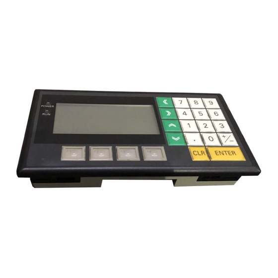
Page 34: Description Of Parts And Settings
Function keys Display Used for direct An LCD screen with a backlight. notifications to the PC. Reference The NT11S comes in two body colors. S NT11S-ST121 : Beige S NT11S-ST121B : Black... - Page 35 DIP switch Set various system statuses with these switches. Reset switch Initializes the NT11S statuses. Note that for the image data memory and the memory switch, the status before the initialization is retained. RS-422A terminal block Connect the PC cable here.
-
Page 36: Dip Switch Settings
Description of Parts and Settings Section 2-1 2-1-2 DIP Switch Settings Set the NT11S operation status with the DIP switches located in the bottom right corner on the rear side of the body. Switch # Function SW2-1 SW2-1 RS-422A terminal resistor connection... - Page 37 It the system program is erased, it will not be possible to use the functions of the NT11S unless another system program is transferred. If the DIP switch settings have been changed when the NT11S is powered, reset the power to the NT11S. The changes with the DIP switches become effective...
-
Page 38: Installation
The panel must not be soiled or warped, and must be able to support an installation that will remain secure and strong. (1) Open a hole, shown below, in the panel and install the NT11S from the front side of the panel. -
Page 39: Power Supply Connection
24 VDC Power Supply S Noise prevention The NT11S has a noise preventive feature against the power supply line noise. To further reduce noise, connect a noise filter to the power line. This will drasti- cally reduce the ground noise. -
Page 40: Grounding
Grounding wire length should be less than 20 m. Note that if grounding wire is used in common with other equipment, or if it is con- nected to a beam of a building, for example, the NT11S might be adversely af- fected by this grounding. -
Page 41: Connecting To The Support Tool
Appendix E “Making the Cable for Connection to the Support Tool”. Reference It is impossible to connect a computer and a PC at the same time to the NT11S. Connect a computer only to transfer the screen data. -
Page 42: Connection To A Pc By The Host Link (Rs-232C Type)
Connection to a PC by the Host Link (RS-232C Type) Connect the NT11S to an OMRON PC by using RS-232C type the host link meth- In order to make a connection to the PC using the host link method (RS-232C type), the “Comm. -
Page 43: Connecting The Nt11S
Connecting to a PC with a 25-pin Connector Use a connector cable with a 25-pin connector on one end and a 9-pin connector on the other end (NT11S side) to connect the NT11S to a PC with a 25-pin connec- tor. -
Page 44: Pc Switch Settings
2-4-3 PC Switch Settings When the NT11S and PC are connected to each other, set the conditions at the PC host link unit or the CPU as given in the table below. The following is a general description of switch settings. - Page 45 Connection to a PC by the Host Link (RS-232C Type) Section 2-4 Connecting to a Host Link Unit S C200H rack-mounting type: C200H-LK201(--V1) [Setting the front switches] Set each switch with a flat blade screwdriver so that the values or symbols in the setting value window agree with the following.
- Page 46 S C-series C200HS, CQM1 Set the operating conditions to the PC system setting area when a C200HS or CQM1 CPU is connected to the NT11S. The PC system setting area (data memory) can be directly accessed from the peripheral tool (LSS etc.).
-
Page 47: Connection To A Pc By The Host Link (Rs-422A Type)
Connect the NT11S to an OMRON PC by using the RS-422A type host link meth- If the distance between the NT11S and the PC is greater than 15 m, this method should be used. The maximum distance over which a connection can be made is 500 m. -
Page 48: Parts Required For Connection
One connector and one connector cover is supplied with the PC. However, a cable of the type recommended by OMRON must be prepared. For details on making the cable, refer to “Making the Cable for Connection to the PC (RS-422A Type)”... -
Page 49: Method For Connection
(max. cable length : 500 m) Reference Carry out class 3 grounding at the FG terminal of the PC. For details, refer to the manual for the PC. Caution Switch off the NT11S power supply before connecting or disconnecting a connec- tor. -
Page 50: Connector Specifications And Wiring For Each Unit
Recive data A RDA (RD--) Recive data B RDB (RD+) S Connecting an NT11S to a C-series host link unit [C-series host link connector specifications] - Applicable host link units: C200H-LK202 (-V1) - Electrical characteristics: Conform to EIA RS-422A - Signal direction: Signal input and output is relative to the host link unit. -
Page 51: Pc Switch Settings
2-5-5 PC Switch Settings When the NT11S and PC are connected to each other, set the conditions at the PC host link unit or the CPU as given in the table below. The following is a general description of switch settings. - Page 52 Connection to a PC by the Host Link (RS-422A Type) Section 2-5 [Setting the rear switches] C200H-LK201(-V1) S 1-to-1/1-to-N selection (DIP switch) Set No. 3 to “ON”. selector switch External S CTS selection (selector switch) 0V (ON) Set this always to “0V” (ON). C200H-LK202(-V1) This type has an RS-422A connector.
-
Page 53: Connection To A Pc By The Nt Link
Connect the NT 11S to an OMRON PC by the NT link method. To connect the NT11S to a PC by the NT link method, the NT11S memory switch for “host communication” must be set for the NT link. For the “host communication”... -
Page 54: Pc Switch Settings
Section 2-6 2-6-3 PC Switch Settings when the NT11S and PC are connected to each other, set the conditions at the PC CPU so as to enable the NT link communications. S C-series C200HS, CQM1 Set the operating conditions to the PC system setting area when a C200HS or CQM1 CPU is connected to the NT11S. -
Page 55: Connecting A Printer
Caution If the connection cable is connected or disconnected while the power of the printer is on, the NT11S may malfunction. Make sure to turn off the power of the printer before connecting or disconnecting the connection cable. EPSON ESC/P... -
Page 57: System Menu Operation
This section describes the operation of the System Menu focusing on the procedure to start up the NT11S. Functions which will be convenient to use the NT11S and those which are useful for the system maintenance are also ex- plained here. -
Page 58: Operation Flow By The System Menu
Follow the procedure below when using the NT11S for the first time or when changing the system. Create the Screen Data Create the screen data to be displayed on the NT11S by using a support tool. For the screen data creation, refer to the “NT-series NT11S Support Tool Opera- tion Manual” (V030-E1-1). -
Page 59: Starting The Nt11S
Follow the procedure below to change the system settings or screen data con- tents. Procedure 1. Switch on the power to the NT11S with two function keys held down to display the System Menu, then change the system settings. For the method for calling the System Menu, refer to the “Operations with the System Menu”... -
Page 60: Operation Modes And The System Menu
Operation Modes and the System Menu Section 3-3 Operation Modes and the System Menu The NT11S operates in either “RUN”, “Transmit”, or “Maintenance” mode. The op- eration modes can be switched by using the System Menu. 3-3-1 System Menu and the Operation Modes Select an operation mode by locating the cursor on the required item with the ["] [#]... -
Page 61: Menu Tree
Section 3-3 3-3-2 Menu Tree The System Menu allows to effect various NT11S functions by using the System keys. The NT11S’s functions with respect to the System Menu are related as shown below. For the operations with the System Menu, refer to the “Operations with the System Menu”... -
Page 62: Operations With The System Menu
Selecting the Menu Items Press the key on the panel of the NT11S to move the highlighting up or down. When the required item is highlighted, press the “ENTER” key to select it. Menu items allow to make the ON/OFF selection or to call subsequent menu or screen. - Page 63 Maintenance Mode The Maintenance Mode menu will be displayed to allow the maintenance of the NT11S system. Switching from the System Menu to the RUN mode The NT11S will exit the System Menu and switch to the RUN mode in the cases mentioned below. S Selecting “Quit” in the System Menu.
-
Page 64: Initializing Memory
Section 3-4 Initializing Memory If the NT11S is used for the first time or if the screen data is ruined and the NT11S cannot be normally started, the memory needs to be initialized. The memory initialization is required in the cases mentioned below. - Page 65 Initializing Memory Section 3-4 Initialization by using the System Menu Initialize the image data memory by following the procedure given below. Select “Maintenance Mode” SYSTEM MENU with the key, then press “EN- Quit TER”. Transmit Mode Maintenance Mode Select “Initialize Memory” with PT Setting key, then press “ENTER”.
-
Page 66: Initialization By Using The Dip Switch (Forced Initialization)
Reference To change the system settings or to register the screen data, set DIP-SW2-2 to OFF and call the System Menu screen by turning on the power to the NT11S while pressing two of the four function keys. The NT11S DIP-SW2-2 is used to set “Screen data forced initialize effective/inef-... -
Page 67: Transferring The System Program
Reference The NT11S uses one connector for the connection to both a PC and a computer. If it has been connected to a PC, disconnect the PC and connect the system trans- fer tool (computer) to the NT11S, and then, transmit the screen data. - Page 68 NT11S correctly. S The power to the NT11S is switched off, or the NT11S is reset, during transfer. S The power to the personal computer that is running the system transfer tool is switched off, or the personal computer is reset, during transfer.
- Page 69 S Transfer is terminated by pressing the ESC key of the personal computer run- ning the system transfer tool. In the event of any of the above, there is a possibility that the NT11S will not oper- ate or that unpredictable malfunctions will occur.
-
Page 70: Registering The Screen Data
Reference The NT11S uses one connector for the connection to both a PC and a computer. If it has been connected to a PC, disconnect the PC and connect the support tool (computer) to the NT11S, and then, transmit the screen data. - Page 71 Registering the Screen Data Section 3-6 Operation 1. Connect the NT11S to the computer on which the support tool is being used, and turn ON the NT11S. 2. Turn ON the computer and start up the support tool. 3. Enter the “Transmit Mode” by operating the menu of the NT11S as mentioned below.
- Page 72 8. You can quit the Transmit Mode and return to the RUN mode by simultaneous- ly pressing any two of the four function keys on the panel of the NT11S. The same result is achieved when the NT11S receives a transfer end instruction from the support tool.
-
Page 73: Setting The Conditions Of Communications With The Pc By Using The Memory Switches
The communications between the NT11S and a PC are called the host commu- nications. The NT11S can be connected to a PC by the host link or NT link. The link can be selected by setting the memory switch. Also, the host link baud rate, automatic reset function, etc. -
Page 74: Selecting The Host Communication Method
3-7-1 Selecting the Host Communication Method The NT11S can be connected to a PC by the host link or NT link. Either link can be selected by setting the “Comm. Type” memory switch. The factory setting has been made to the “Host link”. -
Page 75: Selecting The Host Link Communication Speed
Setting the Conditions of Communications with the PC by Using the Memory Switches Section 3-7 3-7-2 Selecting the Host Link Communication Speed When the host link is used, the baud rate of the communications with the PC can be set. Use the “Baud Rate” switch and select 9600 bps or 19200 bps. The factory setting has been made at 9600 bps. -
Page 76: Selecting The Automatic Reset Function
Setting the Conditions of Communications with the PC by Using the Memory Switches Section 3-7 3-7-3 Selecting the Automatic Reset Function The “Auto-restart” memory switch is used to set whether or not the communication is automatically reset after the occurrence of a communication error. The factory setting has been made at “OFF”. -
Page 77: Selecting The Channel For Communication With The Pc
3-7-4 Selecting the Channel for Communication with the PC The NT11S allows selection of RS-232C or RS-422A as the channel (communica- tion port) for communication with the PC. The channel to be used is selected at the “Comm. Port” item in the memory switch menu. -
Page 78: Starting The Operation
Reference If the NT11S has failed to start correctly; e.g., the start-up screen is not displayed, an error message is displayed, or the screen is not displayed at all, refer to Section 6-2 “Responding to Displayed Error Messages” (page 133) and take appropriate action. -
Page 79: Backlight Off
Section 3-9 Backlight OFF In order to prevent the formation of an afterimage on the screen, and to maximize the service life of the backlight, the NT11S has a function for turning off the back- light. 3-9-1 Turning the Backlight Back ON... - Page 80 Back light OFF Section 3-9 Pressing the [+/--] key while Page: “Backlight OFF” is highlighted Backlight OFF 10min will cause the selection for this item to change cyclically in the Auto-restart sequence “10m” “1h” “None”. S To quit after setting the selection made, press the “ENTER” key. To quit without setting the selection made, press any two function keys simulta- neously.
-
Page 81: 3-10 System Maintenance
System Maintenance Section 3-10 3-10 System Maintenance In order to facilitate maintenance, the NT11S is provided with functions including the I/O check function and a function for confirming the NT11S settings. 3-10-1 I/O Check The I/O check function checks whether the inputs and outputs for the following items are normal. - Page 82 System Maintenance Section 3-10 LCD check Check the LCD of the NT11S by performing the following operations, starting from the system menu. Select “Maintenance Mode” SYSTEM MENU with the key, then press “EN- Quit TER”. Transmit Mode Maintenance Mode Select “I/O Check” with the PT Setting key, then press “ENTER”.
- Page 83 System Maintenance Section 3-10 Key input check Check the numeric keys, arrow keys, and function keys of the NT11S by perform- ing the following operations, starting from the system menu. Select “Maintenance Mode” SYSTEM MENU with the key, then press “EN- Quit TER”.
- Page 84 System Maintenance Section 3-10 Check on communication with the support tool Check the communication between the NT11S and support tool by performing the following operations, starting from the system menu. Select “Maintenance Mode” SYSTEM MENU with the key, then press “EN- Quit TER”.
-
Page 85: Pt Setting Check
Section 3-10 Note The NT11S uses the same connector for connection to the support tool to the PC. If this cable is connected to equipment other than the personal computer running the support tool, disconnect it from this equipment and connect it to the support tool before starting the communications check. -
Page 87: Nt11S Functions
......... . . 4-1-1 Setting the Support Tool for Use with the NT11S . -
Page 88: Creating And Transmitting Screen Data
For the details of the support tool and screen data creation, refer to the “NT-series NT11S Support Tool Operation Manual” (V030-E1-j). 4-1-1 Setting the Support Tool for Use with the NT11S To create the screen data for the NT11S, make settings with the support tool for use with the NT11S. Select “Tool Settings”. -
Page 89: Creating Screen Data
á Select “Tool Settings” in the Main Menu to display the “Tool Settings” screen. Settings of Auto Refresh, Communication Port, etc. are made in this screen. Refer to “Setting the support tool for use with the NT11S” on the previous page. - Page 90 Creating and Transmitting Screen Data Section 4-1 Select “Edit Screen”. á Select a file used for storing the screen data for the NT11S in the “File List” screen. To create a new file, select “New File”. To edit an existing file, select a file to edit.
- Page 91 Creating and Transmitting Screen Data Section 4-1 S PT status control area: Section 5-4 NT11S Status Control (page 122) S PT status notify area: Section 5-5 Notification of the Operating Status to the PC (page 126) S Numeral memory table: 5-2 Memory Tables and Bar Graph (page 106)
- Page 92 Transmit the screen data created by using the support tool to the NT11S screen data memory. Connect the NT11S to the support tool and set the NT11S to Transmit Mode. Then, press the [F6] (Transmit) key in the “File List” screen to transmit the created screen...
-
Page 93: Outline Of Functions
Outline of Functions 4-2-1 NT11S Screen This section gives the outline of the screen which is the basis of all NT11S func- tions. For specific operation procedure using host link/NT link such as screen switching, refer to Section 4-3 Screen Display” (page 80). -
Page 94: Characters And Figures Which Can Be Displayed
Section 4-2 4-2-2 Characters and Figures Which can be Displayed The NT11S screen can display characters, bar graphs, and other various ele- ments. This section describes the types and attributes of the characters and figures which can be displayed and do not need to be changed at all. - Page 95 Outline of Functions Section 4-2 S Enlarged display of the characters and marks The characters and marks can be enlarged to the following scales. Double x1 scale width scale S Reverse and flashing display Reverse display: The display brightness of the character and the background is reversed comparing with the normal display.
-
Page 96: Screen Display
It is possible to set more than one of the following attributes for a screen. Numeral setting attribute This attribute makes it possible to use numeric keys on the panel of the NT11S to input numerical values on screens on which numerical values have to be set. -
Page 97: Memory Tables
[4] enables switching to these screens by numeric key input. Memory Tables The NT11S has the “character-string memory table” for the character data and the “numeral memory table” for numeric data which can be written and updated by the The contents of the memory tables can be set by using the support tool when dis- playing the memory tables on the screen or by editing the table. -
Page 98: Numeral Memory Table
4-4-2 Numeral Memory Table The numeral memory table is an NT11S internal memory used to store the numer- al data. Up to 128 numeral memory tables can be used, and up to eight digits (four bytes) of numeral data (including signs) can be stored in one numeral memory table. -
Page 99: Bar Graphs
Bar Graphs Section 4-5 Bar Graphs The contents of the numeral memory tables of the NT11S can be displayed as bar graphs as well as numeral data. 4-5-1 Bar Graph Functions The bar graph function displays a value in a bar graph form as a percentage to the specified value according to the contents of a numeral memory table. - Page 100 Bar Graphs Section 4-5 S Setting the 100 % value and % display Set a value which corresponds to 100 % for the “100 % value”. The available value range is “0 to 99999999” (max. eight digits). For the “% display”, whether or not the proportion (percentage) of the reference numeral memory table value to the “100 % value”...
-
Page 101: Numeral Setting
Numeral Setting Section 4-6 Numeral Setting The NT11S features a numeral setting function which makes it easy to input nu- merical value on the screen. 4-6-1 The Numeral Setting Function The numeral setting function is used to enter numerical values directly into a nu- meral memory table from the screen. -
Page 102: Using Numeric Keys
Numeral Setting Section 4-6 The details for numeral attributes etc., are largely the same as for numeral display (refer to “Numerals which can be Displayed” (page 82)). 4-6-2 Using Numeric Keys To input numerical data at a numeral setting area during operation, first select the numeral setting at which the data is to be input, and then input the numerical value by pressing the numeric keys. -
Page 103: Menu Screen Function
Section 4-7 Menu Screen Function The NT11S has a function whereby screens can be switched even in the absence of a screen switching instruction from the PC, by using numeric keys on the screen. This function is called the menu screen function. -
Page 104: Password Screen Display Function
Password Screen Display Function Section 4-8 Password Screen Display Function For the purposes of security, the NT11S has a function that requires a password to be input before the specified screen can be displayed. This section explains how to set and use passwords. - Page 105 Password Screen Display Function Section 4-8 Procedure for displaying the password screen Explained here is the procedure for displaying the password screen by specifica- tion from the PC. The password screen is displayed by writing the screen number of the screen for which the password setting was made into the screen switch setting word of the PT status control area.
-
Page 106: Display History Screen Function
If the recorded data is required, print it out before switching the power OFF. Printing out the display history The recorded display history can be printed out at a printer connected to the NT11S. For details on how to do this, see section 4-10 “Daily Report/Display Histo- ry Printing Function” (page 91). -
Page 107: 4-10 Daily Report/Display History Printing Function
Daily Report/Display History Printing Function Section 4-10 4-10 Daily Report/Display History Printing Function The NT11S can print daily reports and display histories in response to instructions from the PC. This section describes the procedure for printing daily reports and display histo- ries. - Page 108 NT20S Production qty: 23 Variable characters LINE2 Variable characters Fixed characters Machine: NT11S Fixed characters Production qty: Numerical value Printing procedure Explained here is the procedure for printing a daily report in response to an instruc- tion from the PC.
-
Page 109: Printing Display Histories
02/06--13:17 0040 PRESS Reference The NT11S does not incorporate a clock. Time data is recorded by referring to the PC clock data. Printing procedure Explained here is the procedure for printing a display history in response to an instruction from the PC. - Page 110 Daily Report/Display History Printing Function Section 4-10 S PC program Create the following PC ladder program: 0110 @ORW(35) PT status control word #0020 Set the display history printing bit only to “1”. PT status control word 0111 @ANDW(34) PT status control word Set the display history printing bit only to “0”.
-
Page 111: Using Host Link/Nt Link
SECTION 5 Using Host Link/NT Link This section describes how the NT11S can be used when using the host link/NT link. Outline of Host Link / NT Link Operation ......... -
Page 112: Outline Of Host Link / Nt Link Operation
5-1-2 Allocatable Bits and Words The following bits and words are allocated to the PC and used for the NT11S op- eration. The range of respective area varies with the type of PC. Refer to Appendix H PC Memory Map (page 160). -
Page 113: Nt11S Status Control And Notification To Pc
NT11S functions. For the detail method of use of the PT status control area and the PT status notify area, refer to Sections 5-4 NT11S Status Control (page 122) and 5-5 Notification of the Operating Status to the PC (page 126). - Page 114 Outline of Host Link / NT Link Operation Section 5-1 Controlling the NT11S Status by Using Allocated Bits and Words ..PT Status Control Area (PC to PT) The PT status control area (PC to PT) is provided to control the NT11S status from the PC.
- Page 115 First word : DM0110 Notifying the NT11S Status by Using Allocated Bits and Words ..PT Status Notify Area (PT to PC) The PT status notify area (PT to PC) is provided to notify the NT11S status changes to the PC. When any NT11S status has changed, such change is written to this area in the PC, and the PC will read the data from this area to check the NT11S status.
- Page 116 Note that this function is not available with the character-string memory table. S PT status (refer to page 126) The NT11S operation status and other information are written with the ON or OFF of the bits as shown below. PT status notify bits...
-
Page 117: Switching The Screen Display
For this function, refer to the “4-7 Menu Screen Function” (page 87). To switch the NT11S screen display by controlling from the PC, write a screen number at the “screen switch setting” in the PT status control area. - Page 118 “screen switch setting word” at the leading edge of the “screen switching strobe” of the PT status notify area. This program enables screen switching by using the Menu screen on the NT11S and eliminates re- peated setting of the same screen number. If the screen switching is not executed on the NT11S, the screen switching strobe does not need to be checked.
-
Page 119: Notifying The Display Screen To The Pc (To Display The Number Of Currently Displayed Screen)
(3) When the screen switch strobe flag turns ON, the number of the currently dis- played screen is read and written to the currently displayed screen word in the PT status notify area. In this case, the NT11S will not write the same screen twice. - Page 120 Outline of Host Link / NT Link Operation Section 5-1 By reading the currently displayed screen word when the screen switch strobe flag has turned ON, the number of the currently displayed screen on the NT11S is dis- played. NT11S...
- Page 121 (bit 11212) turns ON, the contents of DM0100 are transferred to DM0101. The number of the previously displayed screen is stored in word 0101. (2) The new screen number notified by the NT11S is read and transferred to DM0100. The number of the currently displayed screen is stored in DM0100.
-
Page 122: Memory Tables And Bar Graph
Since the character-string memory tables can be allocated to the words in the PC, the PC can write data to the character-string memory tables or the initial values can be set when creating the screen data. Display area where the character-string NT11S memory table No. 2 is allocated Character-string memory table Word The contents are the same while they are displayed. - Page 123 Since numeral memory tables can be allocated to PC words, it is possible to write data into the numeral memory tables from the PC and to set the initial values dur- ing screen data creation. The numeral display area where the NT11S numeral memory table No. 2 is allocated Numeral memory table Word Defect = The contents are the same while they are displayed.
-
Page 124: Allocation Words And Display Of The Memory Tables
Memory Tables and Bar Graph Section 5-2 Setting the Words of the Numeral Memory Table When creating the screen data by using the support tool, make the following set- tings for each numbered numeral: S Initialization setting Set whether or not the PC words are initialized with the numeral memory table initial value registered to the screen data memory when the main power supply is turned ON or reset. - Page 125 Memory Tables and Bar Graph Section 5-2 S Available allocation words The memory tables can be allocated to the following PC areas: Allocation Symbol Symbol Area Name Area Name Numeral Character Data Memory Internal/Special Relay Timer × Counter × Holding Relay Auxiliary Relay Link Relay f: OK...
- Page 126 1 digit. Reference The actual display will vary according to the “zero suppress” setting and decimal fraction setting as well as the contents mentioned above. Refer to the “NT-series NT11S Support Tool Operation Manual” (V030-E1-j).
-
Page 127: Changing Displayed Numerals Or Character Strings (Changing The Contents Of Allocated Words
To change the numerals or character-strings displayed on the NT11S, make changes with the numeral or character-string memory table. To make changes with the numeral or character-string memory table of the NT11S, change the con- tents of words by the PC. - Page 128 Application Example of the Numeral Memory Tables Allocated to the PC Words This example gives the procedure to directly display the contents of the words allo- cated as the numeral memory tables in the PC memory. The NT11S screen dis- play will change as the contents of the PC word change.
- Page 129 S Program operation (1) The contents of word DM0000 are incremented by 1 each second. The value displayed on the NT11S in numeral memory table entry No.1 increases by 1 each second. (2) When the counter in (1) above causes an increase in the most significant dig- its, the contents of word DM0001 are incremented by 1 each second.
-
Page 130: Copying The Memory Table
Refer to “Changing displayed numerals or character -strings” explained before. To change the numerals or character-strings displayed on the NT11S, copy the data between the numeral or character-string memory tables by using the “copy memory table setting” of the PT status control area. - Page 131 Memory Tables and Bar Graph Section 5-2 S Available allocation words The PT status control area can be allocated to the following PC areas: Symbol Area Name Allocated Data memory Internal/Special Relay Timer × Counter × Holding Relay Auxiliary Relay Link Relay f: OK ×: NG...
- Page 132 “copy source memory table number” to the PT status control area (PC to PT). The NT11S reads the area sometimes when the PC is writing the settings. If the “copy source memory table number” has been written first and is changed, unex- pected memory table may possibly be changed.
- Page 133 Copy source memory table No. #0011 Copy source word S Program operation (1) When an error occurs (bit 09000 turns ON), the NT11S displays the message “Error”. (2) When the error is cleared (bit 09000 turns OFF), the NT11S display message reverts to “Normal”.
-
Page 134: Upgrading Bar Graphs (Changing The Contents Of Allocated Words)
The following describes the procedure to upgrade the bar graph display on the NT11S by changing the contents of the allocated words. To change the bar graph display on the NT11S, change the contents of the PC words to which the numeral memory tables have been allocated. -
Page 135: Numeral Setting
This section describes how the numerical data input at an NT11S is ascertained by the PC. In order to determine when numerical data has been input at the NT11S, the nu- meral setting strobe flag in the PT status notify area is used. In order to determine the upgraded numeral memory table number, the “content upgrade memory table”... - Page 136 Numeral Setting Section 5-3 [“Content upgrade memory table” in the PT status notify area and PT status] 15 1413 12 11 10 9 8 7 6 5 4 3 2 1 0 Bit Word Numerl memory table No. (BCD, 3 digits) Content upgrade memory table PT status PT status...
- Page 137 Application Example This example shows the reading of the numeral memory table number after a val- ue has been changed by inputting numerical data at the NT11S. S Setting at the support tool Make the following settings using the support tool.
-
Page 138: Nt11S Status Control
NT11S Status Control Section 5-4 NT11S Status Control The statuses of the NT11S can be controlled from the PC by writing control data to the “PT status control bits” of the PT status control area allocated in the PC memory. - Page 139 ”Display history printing” designates printing of the display history data recorded in the NT11S at a printer. When bit 5 is set ON (set to “1”), all the recorded display history data is printed out once. To print it out a second time, bit 5 must be switched OFF (set to “0”) and then switched back ON (to “1”).
-
Page 140: How To Control Nt11S Functions
S Control timing of PT status control bits The PT status control area (PC ® PT) is not read when the NT11S starts up. It is only read, and control is only executed, when the contents of the PT status con- trol area are changed after the NT11S has been started up. - Page 141 NT11S Status Control Section 5-4 Example use of the PT status control bits The example below shows how the PT status control bits are used to execute daily report printing. S Setting at the support tool Perform the following setting with the support tool.
-
Page 142: Notification Of The Operating Status To The Pc (Determining The Nt11S Operating Status)
Notification of the Operating Status to the PC (Determining the NT11S Operating Status) The status (operating statuses, etc.) of the NT11S can be determined from the PC by reading the “PT status” word in the PT status notify area allocated in the PC memory. - Page 143 Section 5-5 S PT operation status (bit 15) When the NT11S is in the RUN mode this bit is ON (“1”). In other modes, and when the system menu is displayed, it is OFF (“0”). When it is OFF (“0”), the allocated bits and words cannot be read or written to.
-
Page 144: Reading The Nt11S Operating Statuses
This section explains the actual procedures used to determine the NT11S sta- tuses and operating statuses. In order to ascertain the NT11S operating statuses, the PT status notification bits are used. The NT11S automatically notifies information such as operating statuses to the PT status notification bits in the PT status notify area (PT -->... - Page 145 (1) When “PT operating status” (contact 11215) goes OFF (“0”), “1” (NT11S stopped) is sent to DM0001. (2) If “password input error” (contact 11209) comes ON (“1”), while “PT operating status” (contact 11215) is ON (“1”) , “2” (NT11S operating, password input er- ror) is sent to DM0001.
-
Page 147: Troubleshooting And Maintenance
SECTION 6 Troubleshooting and Maintenance This section describes the action to take when NT11S errors occur, and how to carry out maintenance and inspections to prevent the occurrence of errors. Hardware Faults ............. -
Page 148: Hardware Faults
Hardware Faults Section 6-1 Hardware Faults When a fault relating to the operation of the NT11S occurs, find the symptoms in the table below and respond by following the corresponding “Remedy” indicated in the table. NT11S Symptoms Cause Remedy Nothing is displayed on Screen No.0 has been read at the... -
Page 149: Responding To Displayed Error Messages
Responding to Displayed Error Messages Section 6-2 Responding to Displayed Error Messages When the NT11S displays one of the messages indicated below, determine the cause by referring to the table below, and take the action indicated in the “Remedy” column. - Page 150 Transfer the screen corresponding to the specified number from the support tool. 6-2-3 Errors Occurring on Screen Data Initialization and Transfer The table below shows the errors that can occur when data is written to the NT11S screen data memory, and their remedies. Message Cause...
- Page 151 Some error messages are displayed even if the “Automatic Reset” memory switch is set (ON). S Procedure when a communication error occurs When an error message is displayed, press any key on the panel of the NT11S. The screen display will return to the RUN mode. S Display of communication errors...
- Page 152 Overflow Error Overflow Error PC match the settings of the NT11S. Noise caused data corruption during Use a noise-resistant cable if communication occurs communication. in an environment with high levels of noise.
-
Page 153: Inspection And Cleaning
Inspection and Cleaning Section 6-3 Inspection and Cleaning Clean and inspect the NT11S regularly to ensure that it is always used in its opti- mum condition. Cleaning Method If the display is dirty the screen is difficult to see. Clean the screen from time to time as follows. - Page 154 S Be sure to switch the power OFF before replacement. S After replacement, check that the new NT11S is not subject to the same error. S If a faulty unit is returned for repairs, write as detailed a description of the fault as possible and send this description together with the unit to the OMRON address indicated on the back cover of this book.
-
Page 155: Appendices
Specifications Appendix A APPENDIX A Specifications General Specifications Item Specification Power supply voltage 24 VDC Allowable power supply voltage range 20.4 VDC to 26.4 VDC (24 VDC --15% +10%) Power consumption Less than 10W Ambient operating temperature 0 to +50_C (with no freezing) Storage temperature --20 to +70_C (with no freezing) Ambient operating humidity... - Page 156 Numeral setting, password, display history recording, menu screen Max. number of registered screens Screen registration method Transfer screen data created using the support tool to the NT11S. Screen saving method Saved to flash memory (recording format unique to NT11S) (screen data memory)
- Page 157 Specifications Appendix A Display Element Specifications Item Specification Display characters Display characters Normal characters (8 x 16 dots): Alphanumerics and symbols Marks (16 x 16 dots): User-defined pictographs Enlargement function Horizontal magnifications Character display attributes Normal, inverse, flashing, inverse flashing Data Quantities Item Specification...
- Page 158 Specifications Appendix A Communications Specifications [For a Host Link] Item Specification Communications standard EIA RS-232C, RC-422A Communications settings Start-stop synchronization Baud rate: 9600, 19,200 bps Data length: 7 bits Stop bit: 2 bits Parity: Even Connector Connector RS-232C 9-pin, D-SUB connector (male) RS-422A 4-pin terminal block Number of units connected...
- Page 159 GROUND BUSY GROUND PAPER EMPTY GROUND +SELECT [Signal Timing] The NT11S executes communication with a 2-wire handshake system using the STROBE signal and the ACK sig- nal. DATA STROBE BUSY t1, t2 and t3 are each 0.5 msec or longer.
-
Page 160: Dimensions
Dimensions Appendix B APPENDIX B Dimensions Body (NT11S-ST121) (7.99) (4.45) (3.86) 7.5 (0.30) (8.58) 38.2 (1.50) Unit : mm (inch) -
Page 161: Nt11S Installation Environment
NT11S Installation Environment Appendix C APPENDIX C NT11S Installation Environment When installing the PT in the operation panel, observe the following points. See also the section “Getting Starting”. Note S The view angle of the LCD screen is 35_ to the left and 35_ to the right. Install it at a position and height where operators will be able to see it well. -
Page 162: Method For Making The Cable For Connection To The Pc
9-pin, manufactured by OMRON cover When connecting the NT11S to an OMRON PLC CjjH , the connector and the connector cover must be prepared separately since they are not supplied with the CjjH. The connector provided in the CPU unit of the CjjH is a 9-pin connector. For the connection, the following con- nector and connector hood should be prepared. - Page 163 (*1) FG is not used. Correct Use Pin 6 is used to supply the internal 5V source of the NT11S to external destina- tions. Pay special attention to this pin when wiring. Incorrect wiring could cause malfunction or failure of the NT11S.
- Page 164 “0V” (see in the figure). Connect the cable shielding wire to the connector cover and pin 1 at the host link unit end of the cable only. NT11S PC (host link unit) Abbrevi-...
- Page 165 Method for Making the Cable for Connection to the PC Appendix D Connecting an NT11S to a C-Series CQM1, C200HS Series CPU S C-Series CQM1, C200HS Series CPU Unit 9-pin Connector Specifications Applicable CPU: CQM1-CPU21-E C200HS-CPU21-E CQM1-CPU41-E C200HS-CPU23-E CQM1-CPU42-E C200HS-CPU31-E...
- Page 166 C200H-LK202 9-pin, manufactured by JAE When connecting the NT11S to an OMRON PLC CjjH , the connector and the connector cover must be prepared separately since they are not supplied with the CjjH. The connector provided in the CPU unit of the CjjH is a 9-pin connector. For the connection, the following con- nector and connector hood should be prepared.
- Page 167 Method for Making the Cable for Connection to the PC Appendix D Connector Specifications and Wiring for OMRON Units (RS-422A Type) Connecting an NT11S to a C-Series Host Link Unit S C-Series Host Link Connector Specifications S Applicable Host Link Unit:...
- Page 168 Method for Making the Cable for Connection to the PC Appendix D Making the Cable The procedure to make up the cable is described below. Cable Preparation The preparation of the cable differs according to whether or not the shielding wire is to be connected to the FG. S Cable with Shielding Wire Connected to FG (1) Cut the cable to the required length.
- Page 169 Method for Making the Cable for Connection to the PC Appendix D S Cable with Shielding Wire Not Connected to FG (1) Cut the cable to the required length. (2) Remove the external vinyl insulation from the cable with a razor blade. Take care not to damage the shielding underneath.
- Page 170 Method for Making the Cable for Connection to the PC Appendix D Connector Cover Assembly Assemble the connector covers as shown in the diagram below. Aluminum foil tape End connected to FG End not connected to FG...
-
Page 171: Making The Cable For Connection To The Support Tool
The table below indicates the recommended parts for making the connection cable. Name Model Remarks Connector Connector XM2A-2501 25-pin, manufactured by OMRON XM2A-0901 9-pin (Plug), manufactured by OMRON Connector cover Connector cover XM2S-2511 25-pin, manufactured by OMRON XM2S-0911 9-pin, manufactured by OMRON Cable AWG28¢5P... -
Page 172: Nt11S Internal Processing
Periodic Processing When the NT11S is in the RUN mode it executes the following internal processing cyclically. The contents of all the allocated bits and words used for screen display are read from the PC at one time, allowing high-speed processing. - Page 173 Appendix F Event Processing When the status of the NT11S changes during operation, the processing for writing the changed data to the relevant area of the PC memory is executed. This kind of processing is only executed when statuses change. When changes occur simultaneously, the proces- sings are executed in accordance with the order of priority.
-
Page 174: Model List
Features a 9-pin connector for RS-232C connections C-series CQM1-CPU42-E CQM1 CQM1-CPU43-E CQM1-CPU44-E C200HS-CPU21-E Features a 9-pin connector for RS-232C connections C200HS C200HS-CPU23-E C200HS-CPU31-E C200HS-CPU33-E Related Parts and Equipment for PT Name Model Remarks Support Tool NT11S-ZA3AT-EV1 3.5 inch FD for NT11S series... - Page 175 (CO-HC-ESV-3P¢7/0.2) Applicable connectors Name Model Remark Connector Connector XM2A-2501 25-pin, manufactured by OMRON XM2A-0901 9-pin (Plug), manufactured by OMRON DE-9P 9-pin, manufactured by JAE Connector cover Connector cover XM2S-2511 25-pin, manufactured by OMRON XM2S-0911 9-pin, manufactured by OMRON DE-C1-J6 9-pin, manufactured by JAE...
-
Page 176: Pc Memory Map
PC Memory Map Appendix H APPENDIX H PC Memory Map OMRON C-Series Memory Map Link Relay Timer/Count- Area IR Area HR Area AR Area DM Area Area er Area Ladder type Ladder type C200H 0000 to 0255 0000 to 0099 0000 to 0027 0000 to 0063 0000 to 0511... -
Page 177: Special Characters
Special Characters Appendix I APPENDIX I Special Characters English Character Codes Pin 2 of SW2 must be ON to enable English language messages to use the following codes. Example: Hex code is represented by 30, decimal code by 48, and character by 0. Code 20 and 32 in the table represents a space, as indicated by “SP”. - Page 178 Special Characters Appendix I Hex Digits á º í ó ³ ú £ ñ ó Ñ õ ¸ » ¿ Ö ¥ ¡ ø « » Ç : Used as the prefix for mark data codes (2 bytes).
-
Page 179: Index
....Communications with PCs ....Error message when NT11S is started ..Compatible PCs . - Page 180 ........NT11S cannot be normally started ... .
- Page 181 ....... Screen data display on the NT11S ... . .
- Page 182 Tool settings ....... Transferring the system program ... . . Transmit .
- Page 183 Revision History A manual revision code appears as a suffix to the catalog number on the front cover of the manual. Cat. No. V029-E1-2 Revision code The following table outlines the changes made to the manual during each revision. Page numbers refer to the previous version.