Table of Contents
Advertisement
Advertisement
Chapters
Table of Contents
Troubleshooting

Related Manuals for Omron NT11 - 01-2004


Summary of Contents for Omron NT11 - 01-2004
- Page 1 Cat. No. V084-E1-01 NT11 Programmable Terminal USER’S MANUAL...
- Page 2 NT11 Programmable Terminal User’s Manual Produced January 2004...
- Page 4 Ó OMRON, 2004 All rights reserved. No part of this publication may be reproduced, stored in a retrieval system, or transmitted, in any form, or by any means, mechanical, electronic, photocopying, recording, or otherwise, without the prior written permission of OMRON.
-
Page 6: Table Of Contents
Connection to a PLC by the Host Link (RS-422A Type) ......Connection to a PLC by the NT Link (RS-232C Type) ...... - Page 7 Display History Screen Function..........4-10 Daily Report/Display History Printing Function........
- Page 8 Section 3 describes the operation of the System Menu and the maintenance of the NT11. Section 4 describes the functions of the NT11 when it is connected to a PLC. Section 5 describes how to use the NT11 when it is connected to the PLC using the host link or NT link.
- Page 9 [Creating and transferring screen data] • NT-series Support Tool Operation Manual (V061-E1-@) The screens displayed on the NT11 are created with the support tool and transferred to the NT11. This manual describes how to create and transfer screen data.
-
Page 10: Precautions
General Precautions ........ -
Page 11: Intended Audience
This manual provides information for using the Programmable Terminal. Be sure to read this manual before attempting to use the software and keep this manual close at hand for reference during operation. - Page 12 Safety Precautions Caution Indicates information that, if not heeded, could result in relatively serious or mi- nor injury, damage to the product, or faulty operation. WARNING Do not attempt to take the Unit apart and do not touch any internal parts while the power is being supplied. Doing either of these may result in electrical shock.
- Page 13 Safety Precautions...
-
Page 14: Functions Of The Nt11
Operations of NT11 ........ -
Page 15: Getting Starting
• Disassemble or modify the NT11 Cautions on Cleaning To clean the front panel, use a soft, dry cloth. If it is very dirty, use diluted (2%) neutral detergent. Do not use volatile solvents such as benzene, thinner, or a chemically treated cloth. -
Page 16: Operations Of Nt11
PLC or System keys operation is displayed. Receives Data from a PLC NT11 can be connected to a PLC by a host link or NT link and receive neces- sary data from the PLC. Host link, NT link... -
Page 17: Functions Of Nt11
1-3-1 Features Downsized Body • The NT11 has the thinnest depth (31 mm or less in the panel) in the NT series. • It is very compact, with a width of 218 mm and a height of 113 mm. • Features three ports: for RS-232C, RS-422A, and printer output. -
Page 18: Principal Functions Of Nt11
PLC. Other Functions • Communications with a PLC The host link, NT link is used to connect to a PLC for data communication. • System function The system setting and maintenance can be executed by using the System Menu on the screen. -
Page 19: Displays
Section 1-3 1-3-3 Displays The NT11 can display elements such as characters, numeric value, and bar graphs on a screen. The screen data displayed on the NT11 are created by using support tools on a computer. Characters Line 1 Status... -
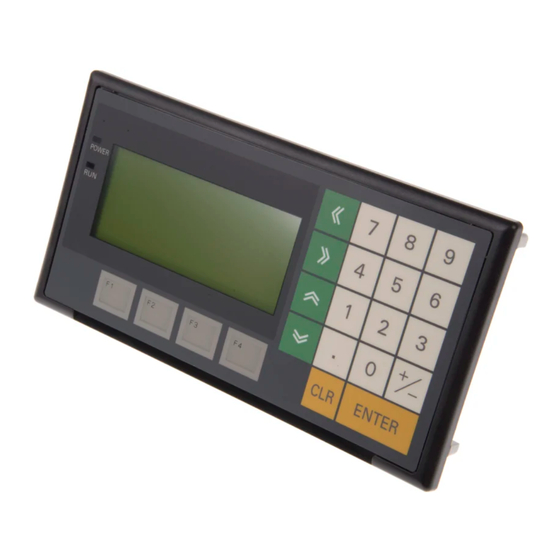
Page 20: System Keys
Numeric keys Arrow keys • Numeric keys These are the numeral keys from [0] to [9], the decimal point key [.], the sign key [+/–], the [CLR] key and the [ENTER] key. These keys are used for inputting numerical values. -
Page 21: System Configuration
System Configuration Section 1-4 System Configuration This section shows the configuration of a system that uses an NT11. For details on product models, refer to Appendix G Model List (page 159). 1-4-1 Peripheral Devices That Can Be Connected The following peripheral devices can be connected to an NT11. -
Page 22: Direct Connection Function
This function allows to read the information to be displayed on the NT11 from the memory area in the PLC and to write it to the memory table in the NT11. Also, the data input on the NT11 can be written to the PLC’s memory area. -
Page 23: Functions Of The Allocated Bits And Words
PLC. By changing the contents of the bits and words, the NT11 can be controlled by the PLC. It is also possible to send data to the PLC by pressing the function keys on the panel of the NT11. - Page 24 The “PT status notify area” is used to notify the changes of the NT11 status. When a change is made in the NT11 status, the change is written to this area in the PLC. By reading the data from the area, the NT11 status can be...
-
Page 25: Before Operating
Before Operating Section 1-6 [Example of the PT status notify area application] When a change is made in the NT11 status, such change will be notified to the PT status notify area as mentioned below. NT11 Numeral memory table entry 13... - Page 26 Section 1-6 Reference Use support tool NT-series Support Tool (NT-ZJCAT1-EV4.7). !Caution Carefully check the operation of all screen data and host programs before using them. Otherwise the system may operate unpredictably. Refer to the following manuals for the equipment and software.
- Page 27 Before Operating Section 1-6...
-
Page 28: Hardware Settings And Connections
Description of Parts ........ -
Page 29: Description Of Parts And Settings
Description of Parts and Settings Section 2-1 Description of Parts and Settings Before getting to the operation, confirm the names and functions of parts. Also set the DIP switches on the NT11. 2-1-1 Description of Parts Front View POWER LED Lit when the power is supplied. - Page 30 Connector for parallel interface connection Contrast control Connect the printer cable here. Use a fine phillips screwdriver. (Interface conforms to Centronics specifications) Turn clockwise to increase the brightness. DIP switch Set various system statuses with these switches. RS-422A terminal block Connect the PLC cable here.
-
Page 31: Dip Switch Settings
Otherwise the system may operate unpredictably. Correct Use Use the “System program erase” function only when changing the system program. It the system program is erased, it will not be possible to use the functions of the NT11 unless another system program is transferred. -
Page 32: Installation
Also confirm that there is no abnormal noise on shaking the unit lightly. The product may malfunction if it is damaged. !Caution During work at the panel, take care to ensure that no metal scraps enter the unit. -
Page 33: Power Supply Connection
NT11. Fit the hook of the fitting in the square hole in the body and tighten the screw with a Phillips head screwdriver while lightly pulling the fitting. -
Page 34: Wiring The Ground Wire
Wire the FG terminal according to the following conditions. 1. Ground according to Figure when there is difference in potential between the PT and host. Do not ground the functional ground of the PT if it is far from the host and one-point grounding is difficult. -
Page 35: Connecting To The Nt Support Tool
Ground correctly to prevent malfunctions caused by noise. Connecting to the NT Support Tool In order to install the system program in the NT11, or to transmit screen data created with the NT Support Tool to the NT11, the NT11 must be connected to a personal computer with an RS-232C cable. -
Page 36: Compatible Plcs
Compatible PLCs Some models and series of OMRON PLCs have the host link function built in. Check the model and series of the PLC against the type of host link unit before making the connections. The compatible PLCs are listed in the table below. -
Page 37: Connecting The Nt11
Connection to a PLC by the Host Link (RS-232C Type) Section 2-4 *2: The CQM1H-CPU11 does not have a built-in RS-232C port, so connect to the PT at the peripheral port with a CS1W-CN118 Connecting Cable. *3: CPU Units of CVM1/CV-series PLCs without the suffix -EV@ cannot be connected. - Page 38 XW2Z-200T 9-pin Û 9-pin XW2Z-500T Note The cable’s tensile load is 30 N. Do not subject it to loads greater than this. Otherwise a discontinuity may occur, causing operation to fail. Wiring for a Host Link Unit Applicable Units: C200H-LK201-EV1...
- Page 39 RS-232C interface interface (9-pin type) (25-pin type) * For Units that have a CTS setting selector switch, RS and CS do not have to be shorted if this switch is set to 0 V. Wiring for Other Applicable Units: Connections...
-
Page 40: Plc Switch Settings
Level 1, 2, 3 Unit No. *1 Set the host link baud rate up to 115,200 bps with the memory switch for “host link baud rate”. For the details, refer to 3-7-2 Selecting the Host Link Communication Speed (page 74). - Page 41 Communication port 2 is a 9-pin connector that allows selection of the RS-232C or RS-422A method. When this port is used with the RS-232C method, the I/O port selector switch on the front of the Unit must be set to RS-232C (the upper position).
- Page 42 Command level Level 1, 2, 3 *1 Set the Host Link baud rate up to 115,200 bps with the memory switch at the NT11. For details, refer to Setting the Host Link Method (page 74). *2 The 1-to-N setting enables BCC (Block Check Character). It is not actually possible to connect more than one NT11 in a single Host Link.
- Page 43 2 stop bits Parity Even Data length ASCII 7 bits Unit # *1 Set the Host Link baud rate at 9,600 bps with the memory switch at the NT11. For details, refer to Setting the Host Link Method (page 74).
- Page 44 Connect to the CPU Unit’s built-in RS-232C port. C200HX/HG/HE(-Z)E • Connect to the CPU Unit’s built-in RS-232C port. • Connect to one of the RS-232C ports (port A or port B) on a Serial Communications Board. CQM1H • Connect to the CPU Unit’s built-in RS-232C port.
- Page 45 Data length ASCII 7 bits Unit # *1 Set the Host Link baud rate at 9,600 bps or 19,200 bps with the memory switch at the NT11. For details, refer to Settings the Host Link Method (page 74). Set the PLC Setup settings directly from a Programming Device (e.g., the CX- Programmer Support Software).
- Page 46 Unit # 00 Connecting to a CPM2C The CPM2C PLCs do not have the same kind of port connectors found on CS1-series PLCs. The CPM2C’s communication port handles both RS-232C and peripheral port connections, which are divided internally. Therefore, when...
- Page 47 Setting the DIP Switches of a C200HX/HG/HE(-Z)E, CQM1, or CQM1H When using a C200HX/HG/HE(-Z)E, CQM1, or CQM1H, the DIP switches on the front panel must be set as shown below in order to make the settings in the PLC Setup (in the DM Area) effective.
- Page 48 ASCII 7 bits Unit No. for the Host Link *1 Set the Host Link baud rate up to 115,200 bps with the memory switch at the NT11. For details, refer to Settings the Host Link Method (page 74). When the baud rate is set to 19,200 bps, the PLC Setup of the CPU Unit need to be changed.
- Page 49 Connection to a PLC by the Host Link (RS-232C Type) Section 2-4 For details on PLC Setup, refer to the SYSMAC CS Series Operation Manual (W339-E1-@) or SYSMAC CJ Series Operation Manual (W393-E1-@). When using the built-in RS-232C port of a CS1G/H, CS1G/H-H, or CJ1G...
- Page 50 Connection to a PLC by the Host Link (RS-232C Type) Section 2-4 Setting the Front Switches Set pins 4 and 5 of the CPU Unit DIP switch in accordance with the port that the NT11 is connected to. CS1G/H, CS1G/H-H...
-
Page 51: Connection To A Plc By The Host Link (Rs-422A Type)
RS-422A method, the host computer and PLC are usually connected in a 1 to N ratio (more than one PLC), but in the special case of the connection between the NT11 and PLC, the ratio is 1 to 1. - Page 52 Connection to a PLC by the Host Link (RS-422A Type) Section 2-5 The following table lists the Units that are equipped with an RS-422A Host Link function compatible with the NT11. Units with Built-in Host Link Function CPU Units Connectable with...
-
Page 53: Parts Required For Connection
OMRON. Make this cable in accordance with the environment (PLC used and transmission distance between the NT11 and PLC). One connector, one connector cover and one cable are required to make up a connecting cable. One connector and one connector cover is supplied with the PLC. -
Page 54: Connector Specifications And Wiring For Each Unit
(max. cable length : 500 m) Reference Carry out class 3 grounding at the FG terminal of the PLC. For details, refer to the manual for the PLC. !Caution Switch off the NT11 power supply before connecting or disconnecting a con- nector. -
Page 55: Plc Switch Settings
NT11 in a single host link. Connecting to a C-series Host Link Unit C200H/C200HS/C200HE(-Z)E/C200HG(-Z)E/C200HX(-Z)E Rack-mounting model: C200H-LK201-V1 Setting the Front Switches Set each switch with a flat blade screwdriver so that the values or symbols in the setting value window agree with the following:... - Page 56 Communication port 2 is a 9-pin connector that allows selection of the RS- 232C or RS-422A method. When this port is used with the RS-422A method, the I/O port selector switch on the front of the Unit must be set to RS-422A (the lower position).
- Page 57 Setting the Front Switches Set the unit number of the Serial Communications Unit with the rotary switch on the front of the Unit. Set the unit number with a flat blade screwdriver. Also, set the communications mode switch to select 4-wire (RS-422A) communica- tions and turn ON the terminator switch to enable the terminating resistance.
- Page 58 Data length ASCII 7 bits Unit # *1 Set the Host Link baud rate at 9,600 bps or 19,200 bps with the Comm. Speed memory switch at the NT11. For details, refer to Setting the Host Link Method (page 74).
- Page 59 RS-232C port and a peripheral port.) Reference • There are no Serial Communications Boards for the C200HX/HG/HE(-Z)E in which port B is the RS-422A port. • There are no Serial Communications Boards for the CQM1H in which port 1 is the RS-422A port.
- Page 60 Data length ASCII 7 bits Unit # *1 Set the Host Link baud rate at 9,600 bps or 19,200 bps with the Comm. Speed at the NT11. For details, refer to Setting the Host Link Method (page 74). Set the PLC Setup settings directly from a Programming Device (e.g., CX- Programmer).
- Page 61 Unit # 00 Connecting to a CPM2C Only the CPM2C PLCs do not have the same kind of port connectors found on CS/CJ-series PLCs. The CPM2C’s communication port handles both RS- 232C and peripheral port connections, which are divided internally. Therefore,...
- Page 62 Settings are written from the Programming Device (a Programming Console or CX-Programmer) directly into the allocated DM Area settings (PLC Setup) of the CPU Unit. After the settings are written, they become effective by turn- ing the power ON, restarting the Unit, restarting the communication port, or executing the STUP instruction.
-
Page 63: Connection To A Plc By The Nt Link (Rs-232C Type)
Connect the NT11 to an OMRON PLC by the NT link method. To connect the NT11 to a PLC by the NT link method, the NT11 memory switch for “host communication” must be set for the NT link. For the “host communication”... - Page 64 Connection to a PLC by the NT Link (RS-232C Type) Section 2-6 The hosts that can be connected to the NT11 by the 1:1 NT Link using the RS-232C ports of both Units are indicated in the table below. PLC Series...
- Page 65 DM6650 *1 RS-232C port of the Communication Board *2 RS-232C port of the Serial Communications Board For details on operations relating to the PLC Setup, refer to the manual for the PLC that is used. Connecting to a CPM2C The CPM2C PLCs do not have the same kind of port connectors found on CS/ CJ-series PLCs.
- Page 66 Setting the DIP Switches on the Front of a C200HX/HG/HE(-Z)E, CQM1, CQM1H When using a C200HX/HG/HE(-Z)E, CQM1, or CQM1H, the DIP switches on the front panel must be set as shown below in order to make the settings in the PLC Setup (data memory) effective. C200HX/HG/HE(-Z)E...
-
Page 67: Connecting The Nt11
!Caution After connecting a communication cable, always secure it with the screws. Otherwise the cable may disconnect, causing operation to fail. !Caution The cable’s tensile load is 30 N. Do not subject it to loads greater than this. Otherwise a discontinuity may occur, causing operation to fail. -
Page 68: Connection To A Plc By The Nt Link (Rs-422A Type)
• The CQM1H CPU Units can be connected by the RS-422A 1:1 NT Link method by installing a Serial Communications Board. Check the model and series of the PLC and the type of installed Serial Com- munications Board before making connections. - Page 69 Connection to a PLC by the NT Link (RS-422A Type) Section 2-7 The 1:1 NT Link method cannot be used using RS-485. To use the 1:1 NT Link method, connect by RS-422A. NT link connection using RS-422A/485 is not possible with the CPM1, CPM2A, and CPM2C.
-
Page 70: Connecting A Printer
3 meters. !Caution If the connection cable is connected or disconnected while the power of the printer is on, the NT11 may malfunction. Make sure to turn off the power of the printer before connecting or disconnecting the connection cable. - Page 71 Connecting a Printer Section 2-8...
-
Page 72: System Menu Operation
Initialization by Using the DIP Switch (Forced Initialization)..Transferring the System Program ........ -
Page 73: Operation Flow By The System Menu
Follow the procedure below when using the NT11 for the first time or when changing the system. Create the Screen Data Create the screen data to be displayed on the NT11 by using a support tool. For the screen data creation, refer to the “NT-series NT11 Support Tool Oper- ation Manual” (V030-E1-1). -
Page 74: Operation Modes And The System Menu
Select an operation mode by locating the cursor on the required item with the [ ] [ ¯ ] keys, then press [Enter] to confirm the selection. The operation modes with respect to the System Menu are related to each other as shown below. -
Page 75: Menu Tree
System Menu. Note Make sure that DIP SW2-4 “Switching to the System Menu enabled/disabled” is set to OFF (enabled). If the setting is ON (disabled), the System Menu will not be displayed by following the procedure given below. Displaying the System... - Page 76 Mode nance of the NT11 system. Switching from the System Menu to the RUN mode The NT11 will exit the System Menu and switch to the RUN mode in the cases mentioned below. • Selecting “Quit” in the System Menu.
-
Page 77: Initializing Memory
Section 3-4 Initializing Memory If the NT11 is used for the first time or if the screen data is ruined and the NT11 cannot be normally started, the memory needs to be initialized. The memory initialization is required in the cases mentioned below. -
Page 78: Initialization By Using The Dip Switch (Forced Initialization)
(Quit:F3+F4) You can quit without initializing the memory by simultaneously pressing any two of the function keys while the “Initialize Screen Memory?” screen is dis- played. When the screen data memory initialization has been completed, transfer the screen data from the support tool. -
Page 79: Transferring The System Program
Reference To change the system settings or to register the screen data, set DIP-SW2-2 to OFF and call the System Menu screen by turning on the power to the NT11 while pressing two of the four function keys. The NT11 DIP-SW2-2 is used to set “Screen data forced initialize effective/ ineffective”. - Page 80 Transferring the System Program Section 3-5 Note An NT11 which has no system program registered in it will be able to execute only installation function. For details on system transfer tool operations, refer to the NT-series Support Tool Operation Manual (V061-E1-@).
- Page 81 • Transfer is terminated by pressing the ESC key of the personal computer running the system transfer tool. In the event of any of the above, there is a possibility that the NT11 will not operate or that unpredictable malfunctions will occur.
-
Page 82: Registering The Screen Data
Registering the Screen Data Section 3-6 2. Press the “return” key if you want to quit without erasing the program. If you do want to erase the program, press any two of the function keys simulta- neously: this will start erasure of the program. - Page 83 Transmitting the Screen Data from the Support Tool To transmit the screen data from the support tool to the NT11, connect the NT11 to the computer on which the support tool is being used, and follow the procedure below. Reference The NT11 uses one connector for the connection to both a PLC and a com- puter.
-
Page 84: Setting The Conditions Of Communications With The Plc By Using The Memory Switches
The communications between the NT11 and a PLC are called the host com- munications. The NT11 can be connected to a PLC by the host link or NT link. The link can be selected by setting the memory switch. Also, the host link baud rate, auto- matic reset function, etc. - Page 85 Setting the Conditions of Communications with the PLC by Using the Memory Switches Section 3-7 [ Memory switch menu ] [Memory SW1] Page: [Memory SW2] Page: Backlight OFF: 10min Com. Type: Host Link Auto-restart: Baud Rate: 9600BPS History Data: Keep Com.
-
Page 86: Selecting The Host Communication Method
3-7-1 Selecting the Host Communication Method The NT11 can be connected to a PLC by the host link or NT link. Either link can be selected by setting the “Comm. Type” memory switch. The factory set- ting has been made to the “Host link”. -
Page 87: Selecting The Host Link Communication Speed
3-7-2 Selecting the Host Link Communication Speed When the host link is used, the baud rate of the communications with the PLC can be set. Use the “Baud Rate” switch and select 9,600 bps or 19,200 bps. The factory setting has been made at 9,600 bps. -
Page 88: Selecting The Automatic Restart Function
“No” and “Yes”. To quit after setting the selection made, press the “ENTER” key. To quit with- out setting the selection made, press any two function keys simultaneously. • “Yes”: If a communication error has occurred, corresponding error mes- sage is displayed and the operation stops. -
Page 89: Selecting The Channel For Communication With The Plc
Port: RS-232C alternate between “RS- 232C” and “RS-422”. To quit after setting the selection made, press the “ENTER” key. To quit with- out setting the selection made, press any two function keys simultaneously. Reference Select the system that is supported by the PLC to be connected. -
Page 90: Starting The Operation
The “History Data” memory switch is used to set whether to erase the history data when the power supply is turned ON. The history data is backed up by a capacitor in the NT11. (The backup time is 5 minutes minimum and 16 hours at 25 °... -
Page 91: Backlight Off
After the backlight has been switched off by actuation of the backlight OFF function, it will come back on in response to any key operation on the panel of the NT11, if a screen is switched or redisplayed by the PLC, or if a backlight ON instruction is received from the PLC. - Page 92 OFF function is used, and - if it is used - what length of time will elapse before the backlight goes OFF. The setting on shipment specifies that the backlight will go OFF after a period of ten minutes during which there are no operations.
-
Page 93: 3-10 System Maintenance
Select “LED Check” with [Device Check] key, then press “ENTER”. LED Check LCD Check Key Input Check The “RUN” LED on the panel of the NT11 will blink. • To quit the LED check, press any two of the function keys simultaneously. - Page 94 LCD Check Key Input Check • In the LCD check, all of the dots that comprise the screen are displayed, one at a time, starting at the top left corner of the screen. The LCD check is completed when all the dots are displayed.
- Page 95 NT11 in turn. If the corresponding key in the display is highlighted when the panel key is pressed, it indicates that the key is operating normally. • To quit the key input check, press any two of the function keys simulta- neously.
- Page 96 Tool I/F Input Check Print Out Check TOOL I/F INPUT CHECK • The data received from the connected support tool is displayed in hexa- decimal notation. • To quit the check on communication with the support tool, press any two function keys simultaneously.
-
Page 97: 3-10-2 Pt Setting Check
Section 3-10 Note The NT11 uses the same connector for connection to the support tool to the PLC. If this cable is connected to equipment other than the personal computer running the support tool, disconnect it from this equipment and connect it to the support tool before starting the communications check. -
Page 98: Nt11 Functions
Screen Attributes ........ -
Page 99: Outline Of Functions
Outline of Functions 4-1-1 NT11 Screen This section gives the outline of the screen which is the basis of all NT11 func- tions. For specific operation procedure using host link/NT link such as screen switching, refer to 4-2 Screen Display (page 87). -
Page 100: Screen Display
Screen Display Section 4-2 Types and Attributes of Characters and Figures The following types of characters can be input by using the support tool and be displayed during operation. Character Dots Character Set Maximum Number of Type (vertical x Characters Displayed in One... -
Page 101: Screen Attributes
Assigning an attribute to a screen makes it capable of a special function when it is displayed. For example, when an attempt is made to display a screen for which the “password” attribute is set, a message requesting input of the pass- word will be displayed and the specified screen will not be displayed until the password has been input. -
Page 102: Areas For Control/Notification
The allocations must be made without exceeding respective area range. [OMRON PLCs] Words Allocated for the PT Status Control Area Words can be allocated for the PT status control area (host « PT) in the fol- lowing host (PLC) areas. Symbol... -
Page 103: Nt11 Status Control And Notification To Plc
NT11 functions. For the detail method of use of the PT status control area and the PT status notify area, refer to 5-5 NT11 Status Control (page 129) and 5-6 Notification of the Operating Status to the PLC (Determining the NT11 Operating Status) (page 132). - Page 104 Areas for Control/Notification Section 4-3 Controlling the NT11 Status by Using Allocated Bits and Words ..PT Status Control Area (PLC to PT) The PT status control area (PLC to PT) is provided to control the NT11 status from the PLC. When data is written to this area in the PLC, the NT11 will read the data and operates according to the data.
- Page 105 First word: DM0110 Notifying the NT11 Status by Using Allocated Bits and Words ..PT Status Notify Area (PT to PLC) The PT status notify area (PT to PLC) is provided to notify the NT11 status changes to the PLC. When any NT11 status has changed, such change is written to this area in the PLC, and the PLC will read the data from this area to check the NT11 status.
- Page 106 ON (1). After this is notified to the PLC, this flag reverts to OFF (0). Checking the status of this flag will provide a sim- ple method of checking if a number has been input from the NT11.
-
Page 107: Memory Tables
The range of each memory area differs according to the PLC. Refer to Appen- dix D Making the Cable on page 153. !Caution Set so that there is no overlap between the PT status control area and PT sta- tus notify area. Otherwise the system may operate unpredictably. -
Page 108: Numeral Memory Table
The numeral data are displayed in designated display areas as right-aligned. If the number of digits of a numeral data is smaller than that of the display area, number “0”s will be displayed at the vacant digits. These “0”s will not be... -
Page 109: Bar Graphs
4-5-1 Bar Graph Functions The bar graph function displays a value in a bar graph form as a percentage to the specified value according to the contents of a numeral memory table entry. Up to 4 bar graphs can be registered in one screen. -
Page 110: Numeral Setting
Numeral Setting Section 4-6 • Display of negative values (less than 0%) The bar graph is displayed in the range of 0% to 100%. The end of the bar graph indicates 0%. Values below 0% are indicated as 0%. % display... -
Page 111: Using Numeric Keys
To select other numeral setting areas, use the arrow keys. By using these keys, the cursor can be shifted between multiple numeral set- ting areas (to select the one where data is to be input) in the way shown in the figure below. 6563... -
Page 112: Menu Screen Function
1 through 4. If one of these numeric keys is pressed during operation, the screen whose number was assigned to the key will be displayed. At the same time, the screen number of the destination screen is notified to the PLC. -
Page 113: Password Screen Display Function
• The password for a password screen is input using the numeric keys on the panel of the NT11. • When a password is input, it is not displayed on the screen. Only a box shaped cursor is displayed. • The input password is checked after input of the fourth digit. There is no need to press the “ENTER”... -
Page 114: Display History Screen Function
The display history screen function is a function that records the display times, screen numbers, and screen comments of screens for which the dis- play history attribute has been set using the support tool, in the order in which they were displayed. -
Page 115: 4-10 Daily Report/Display History Printing Function
• Printers of the following type can be connected to the NT11: Models compatible with EPSON standard code (ESC/P) • The history data can be backed up by a capacitor for 16 hours at 25 ° C. To enable backing up the history data, the setting must be changed from the System Menu. - Page 116 To designate printing, bit 4 of the PT status control area is set to “1”. One report is printed each time bit 4 is set to “1”. To print the report again, the bit status must be returned to “0” and then set to “1” again.
-
Page 117: 4-10-2 Printing Display Histories
To designate printing, bit 5 of the PT status control area is set to “1”. One report is printed each time bit 5 is set to “1”. To print the report again, the bit status must be returned to “0” and then set to “1” again. - Page 118 1,2,3... 1. When CIO/IR 0110 comes ON, the display history printing bit (bit 5) of the PT status control area is set to “1”. The status of bits other than bit 5 re- mains unchanged. When bit 5 is set to “1”, the display history is printed.
- Page 119 Daily Report/Display History Printing Function Section 4-10...
-
Page 120: Using Host Link/Nt Link
Screen Creation Procedure ........ -
Page 121: Screen Creation Procedure
Screen Creation Procedure Follow the procedure shown below to create screens for the NT11. The following gives the procedure assuming that the setting for the PT has been completed. The operating procedure for a Support Tool is not given here. For the operating procedure for the Support Tool, refer to the NT-series Support Tool Version 4.7 for Windows Operation Manual (V061-E1-@). -
Page 122: Outline Of Host Link/Nt Link Operation
Setting the Clock Data Area (NT21 only) Set the address of the first word to allocate as the Clock Data Area in the host so that the clock data can be read from the host. SECTION 4 NT11 Functions. Creating and Correcting a Screen After designating a screen, set the screen properties and register elements for the screen or correct the screen. -
Page 123: Switching The Screen Display
PT status control setting [Screen switch setting in the PT status control area] PT status notify bits 15 14 13 12 11 10 9 8 7 6 5 4 3 2 1 0 Bit Screen No. (4-digit BCD) Screen switch setting... - Page 124 Outline of Host Link/NT Link Operation Section 5-2 Words Allocated for the PT Status Control Area Words can be allocated for the PT status control area (host « PT) in the fol- lowing host (PLC) areas. Symbol C-series PLCs Allocation...
-
Page 125: Notifying The Display Screen To The Plc
3. When the screen switch strobe flag turns ON, the number of the currently displayed screen is read and written to the currently displayed screen word in the PT status notify area. In this case, the NT11 will not write the same screen twice. - Page 126 [Currently displayed screen] and [PT status] words in the PT status notify area 15 14 13 12 11 10 9 8 7 6 5 4 3 2 1 0 Bit Word Screen No. (4-digit BCD)* Screen switch setting...
- Page 127 D Making the Cable on page 153. Procedure 1. Use the support tool to allocate the PT status notify area (PT to PLC) to the PLC memory. 2. Create a PLC program to read the “currently displayed screen word” in the PT status notify area when the “screen switch strobe flag”...
-
Page 128: Memory Table Entries And Bar Graph
PLC using the host link/NT link. For the functions relating to memory tables and bar graphs, refer to 4-3 Areas for Control/Notification (page 89) and 4-5 Bar Graphs (page 96), respectively. - Page 129 • Number of registration words Set the number of words within 2 words required for registering the numer- al data. One word can store up to 4 digits. Two words can store up to 8 dig- its. • Setting the words for the numeral memory table entries...
-
Page 130: Allocation Words And Display Of Memory Table Entries
Set the word type and the first word. The number of words required for allocat- ing a memory table entry and the areas to which a memory table entry can be allocated vary between the character-string memory table and the numeral memory table. - Page 131 Memory Table Entries and Bar Graph Section 5-3 Allocated Words Either one or two words can be allocated at the host for each numeral mem- ory entry. Words can be allocated in the following host (PLC) areas. Symbol C-series PLCs...
- Page 132 Numerals can be displayed in three different ways according to the con- tents of the numeral memory table entry, as mentioned below. The most significant digit (digit 4 of a single word or digit 8 of a double word) is processed in different ways.
- Page 133 The following describes the procedure to change displayed numerals or char- acter-strings by changing the contents of the allocated words.Numerals and character-strings can be changed also by making a copy of the memory table entries. Refer to “Copying a memory table entry” explained later.
-
Page 134: Copying Memory Table Entries
DM0002 Word for No. 2 • Program operation 1. The contents of word DM0000 are incremented by 1 each second. The val- ue displayed on the NT11 in numeral memory table entry No. 1 increases by 1 each second. 2. When the counter in (1) above causes an increase in the most significant digits, the contents of word DM0001 are incremented by 1 each second. - Page 135 [“Copy memory table setting” of the PT status control area] 15 14 13 12 11 10 9 8 7 6 5 4 3 2 1 0 Bit Word Copy source memory table No.
- Page 136 The range of respective area varies with the type of PLC. Refer to Appendix H Special Characters (page 163). Reference 1. Use the support tool to allocate the PT status control area (PLC to PT) to the PLC memory. 2. Register the memory table entries for the numerals and character-strings to be displayed when creating the screen data by using the support tool.
- Page 137 #0011 Copy source word • Program operation 1. When an error occurs (bit 09000 turns ON), the NT11 displays the mes- sage “Error”. 2. When the error is cleared (bit 09000 turns OFF), the NT11 display mes- sage reverts to “Normal”.
-
Page 138: Upgrading Bar Graphs (Changing The Contents Of Allocated Words)
The following describes the procedure to upgrade the bar graph display on the NT11 by changing the contents of the allocated words. To change the bar graph display on the NT11, change the contents of the PLC words to which the numeral memory table entries have been allocated. -
Page 139: Numeral Setting
Start + 1 [“Content upgrade memory table entry” in the PT status notify area and PT status] 15 14 13 12 11 10 9 8 7 6 5 4 3 2 1 0 Bit Word Content upgrade memory table entry Numeral memory table entry No. - Page 140 *2 The EM Area is supported only by the C200HX/HG/HE (-Z)E PLCs. The range of each memory area differs according to Appendix H Special Characters (page 163) for more details. 1. Use the support tool to allocate the PT status notify area (PT ® PLC) to the Procedure PLC memory.
- Page 141 DM 0105 (in this case it is 003 or 004). If the numeral memory table entry is allocated to a PLC word, the value in- put to it can be read easily by referring to the allocated word.
-
Page 142: Nt11 Status Control
5-5-1 Controllable NT11 Functions [“PT status control bits” of the PT status control area] PT status control bits 15 14 13 12 11 10 9 8 7 6 5 4 3 2 1 0 Bit Word PT status control designations... -
Page 143: How To Control Nt11 Functions
”Display history printing” designates printing of the display history data re- corded in the NT11 at a printer. When bit 5 is set ON (set to “1”), all the recorded display history data is printed out once. To print it out a second time, bit 5 must be switched OFF (set to “0”) and then switched back ON... - Page 144 • Program operation 1. When CIO/IR 00110 comes ON, the daily report printing bit (bit 4) of the PT status control area is set to “1”. The status of bits other than bit 4 re- mains unchanged. When bit 4 is set to “1”, the daily report is printed.
-
Page 145: Notification Of The Operating Status To The Plc (Determining The Nt11 Operating Status)
Section 5-6 2. When CIO/IR 00111 comes ON, the daily report printing bit (bit 4) of the PT status control area is set to “0”. The status of bits other than bit 4 re- mains unchanged. Notification of the Operating Status to the PLC (Determining the NT11 Operating Status) The status (operating statuses, etc.) of the NT11 can be determined from the... -
Page 146: Reading The Nt11 Operating Statuses
The PT status notify area (PT ® PLC) can be allocated to the PLC memory areas listed in the following table. Words can be allocated for the PT status notify area (PT ® host) in the follow- Words Allocated of the PT Status Notify Area ing host (PLC) areas. - Page 147 The range of each memory area differs according to the PLC type. Appen- dix H Special Characters (page 163) for more details. 1. Use the support tool to allocate the PT status notify area (PT ® PLC) to the Procedure PLC memory.
-
Page 148: Troubleshooting And Maintenance
Inspection and Cleaning ........ -
Page 149: Troubleshooting
Troubleshooting Section 6-1 Troubleshooting When a fault relating to the operation of the NT11 occurs, find the symptoms in the table below and respond by following the corresponding Remedy indi- cated in the table. Note 1. Confirm system safety before turning the power ON/OFF. - Page 150 Remedy The memory table display Since the memory table entry is allo- When the contents of the memory table entry are set contents differ from the ini- cated to the host memory, the display as a fixed values, do not allocate the memory table...
-
Page 151: Responding To Displayed Error Messages
6-2-1 Errors Occurring at Start of Operation and Their Remedies The table below shows the errors that can occur when the power to the NT11 is turned ON and when operation starts, and their remedies. Message Cause Remedy [No Comm. -
Page 152: Errors Occurring During Operation And Their Remedies
NT11. 6-2-3 Errors Occurring on Screen Data Initialization and Transmission The table below shows the errors that can occur when the NT11 data is initial- ized, and during data setting and transmission, and their remedies. Message Cause... -
Page 153: Errors In The System Installer Mode And Their Remedies
Operation When When an error message is displayed, press the OK touch switch displayed on Communication Errors the screen. The NT11 will return to the screen that was displayed before the Occur error occurred, and operation will restart. Display of Communication... - Page 154 • Time out error • Data over flow error • PLC unit number error (host link only) • NAK received (in the case of the host link, the end code is also displayed) • Undefined command error Send Errors The following errors can occur when receiving data.
-
Page 155: Inspection And Cleaning
If the display is dirty the screen is difficult to see. Clean the screen from time to time as follows. • In daily cleaning, wipe the display with a soft dry cloth. If the soiling is par- ticularly heavy, attempting to remove it by wiping with a dry cloth may damage the front sheet of the Unit. - Page 156 • After replacement, check that the new NT11 is not subject to the same error. • If a faulty unit is returned for repairs, write as detailed a description of the fault as possible and send this description together with the unit to the OMRON address indicated on the back cover of this book.
- Page 157 Inspection and Cleaning Section 6-3...
-
Page 158: A Specifications
Noise resistance Conforms to IEC61000-4-4, 2K (power lines) Vibration resistance 10 to 57 Hz with 0.075 mm amplitude and 57 to 150 Hz with 9.8 m/s acceler- ation for 30 min in each of X, Y, and Z directions Shock resistance... - Page 159 Specifications Appendix A Display/Panel Specifications Note In order to improve the performance of displays, liquid crystal devices may be changed without notice. Item Specification Display screen Dot matrix of STN liquid crystal display panel Backlight • Number of dots: 160 ´ 64 •...
- Page 160 CD-ROM (for Windows 95, 98, Me, NT-ZJCAT1-EV4 XP, NT, 2000) Function Key Sheets 10 sheets for replacement for beige NT11-CKF01 10 sheets for replacement for black NT11-CKF01B The PT body incorporated the communication interface, screen memory, and a flash ROM that downloads the system program.
- Page 161 GROUND -ACK GROUND BUSY GROUND PAPER EMPTY +SELECT [Signal Timing] The NT11 executes communication with a 2-wire handshake system using the STROBE signal and the ACK signal. DATA STROBE BUSY t1, t2 and t3 are each 0.5 µs or longer.
-
Page 162: B Dimensions
Appendix B Dimensions Body (NT11-SF121(B)-EV1) 38.2... - Page 163 Dimensions Appendix B...
-
Page 164: Transporting And Storing The Nt11
Appendix C Transporting and Storing the NT11 • When transporting the NT11, use the packaging intended for it. • When storing the NT11, observe the following conditions. –20 to 70 ° C Storage ambient temperature: 0 to 70 ° C: 85%... - Page 165 Transporting and Storing the NT11 Appendix C...
-
Page 166: Making The Cable
Also refer to this procedure for making a connecting cable for use with RS-422A/485 type connections. Cable Preparation The preparation of the cable differs according to whether or not the shielding wire is to be connected to the FG. Cable with Shield Connected to FG 1. - Page 167 Soldering iron Heat-shrink tube (F, 1.5 mm dia., l = 10 mm) 4. Push the heat shrink tube over the soldered joint and heat the tube to shrink it in place. Heat-shrink tube Hood Assembly Assemble the connector hood as shown below.
-
Page 168: Making The Cable For Connecting A Personal Computer
Refer to the following when making a cable for connecting the NT Support Tool. Assembly of Connecting Cables Wiring should be carried out in one of the following ways, depending on the type of RS-232C connector. 25-pin Connector Personal computer... - Page 169 (1) One XM2S-0911 (for PT) and either one XM2S-0911 or -0913 (for your personal computer) are needed. (2) Check that the current capacity of the equipment to be supplied is within 150 mA before using the +5 V output of pin No.6. Otherwise, the product may malfunction. The +5 V output of the unit delivers...
-
Page 170: Nt11 Internal Processing
Periodic Processing When the NT11 is in the RUN mode it executes the following internal processing cyclically. The contents of all the allocated bits and words used for screen display are read from the PLC at one time, allowing high-speed processing. - Page 171 Appendix F Event Processing When the status of the NT11 changes during operation, the processing for writing the changed data to the rel- evant area of the PLC memory is executed. This kind of processing is only executed when statuses change. When changes occur simultaneously, the pro- cess is executed in accordance with the order of priority.
-
Page 172: Model List
Model Specification Applicable PLC CS1W-SCU21 RS-232C (2 ports) CS-series Rack-mounting Unit CS1G/H, CS1G/H-H CJ1W-SCU41 Features an RS-422A/485 port (port 1) and an RS-232C port CJ-series (port 2). CJ1G CPU Units for Connection via Host Link Model Specification PLC Type CPM1-10CDR-@... - Page 173 Features a connector for RS-232C connections (9-pin) CS-series, high-speed CS1H-CPU64H CS1H-H CS1H-CPU65H CS1H-CPU66H CS1H-CPU67H CJ1G-CPU44 Features a connector for RS-232C connections (9-pin) CJ-series CJ1G-CPU45 CJ1G CVM1-CPU01-EV2 Features a connector for RS-232C connections (select- CVM1/CV-series CVM1-CPU11-EV2 able/9-pin) CVM1 CVM1-CPU21-EV2 * One of the Serial Communications Boards C200HW-COM02/COM04/COM05/COM06-EV1 is required.
- Page 174 Connector and Connector hood Cable AWG28´5P IFVV-SB Multi-core shielded cable, made by Fujikura Ltd. CO-MA-VV-SB 5P´28AWG Multi-core shielded cable, made by Hitachi Cable, Ltd. * One XM2S-0911 (for PT) and either one XM2S-0911 or -0913 (for your personal computer) are needed.
- Page 175 Links the RS-232C port of an NT11 and the peripheral port of a CPM1, CPM2A, CPM2C, SRM1 (compatible with host link, and NT Link (1:1)) CPM1-CIF11 Links the RS-422A port of a Link Adapter and the peripheral port of a CPM1, CPM2A, CPM2C, SRM1 (compatible with host link) Related Parts and Equipment for PT...
-
Page 176: Special Characters
Special Characters English Character Codes Pin 2 of SW2 must be ON to enable English language messages to use the following codes. Example: Hex code is represented by 30, decimal code by 48, and character by 0. Code 20 and 32 in the table represents a space, as indicated by “SP”. - Page 177 Special Characters Appendix H Hex Digits á ± í ³ ó £ ú ó ñ õ Ñ ¸ » ° ¿ · Ö ¥ ¡ « Ç » * Used as the prefix for mark data codes (2 bytes).
-
Page 178: Index
Block Check Character Serial Communications Boards settings startup direct connection function cables display assembly display history preparation printing characters display history screen function character codes display screen cleaning notifying Programmable Controller communication port switching selecting examples Communications Units DM Area models... - Page 179 System Installer mode LCD check event processing LED check features maintenance Function Key Sheet maintenance mode key operations function keys marks functional ground (FG) terminal memory switches auto-restart history data memory tables history data allocations selecting character-string Host I/F Unit changing...
- Page 180 NT11S Programmable Terminals numeral setting function models numeric keys Programming Tools numeric values manuals PT settings PT status control area allocations PT status control bits operating status application example notifying Programmable Controller reading PT status notification bits application example operation modes...
- Page 181 Support Software switch settings Programmable Controllers See also DIP switches. system configuration System Installer errors manual system keys precautions System Menu displaying functions initializing system program erasing...
-
Page 182: Revision History
Revision History A manual revision code appears as a suffix to the catalog number on the front cover of the manual. Cat. No. V084-E1-01 Revision code The following table outlines the changes made to the manual during each revision. Page numbers refer to the previous version. - Page 183 Revision History...
- Page 184 Regional Headquarters OMRON EUROPE B.V. Wegalaan 67-69, NL-2132 JD Hoofddorp The Netherlands Tel: (31)2356-81-300/Fax: (31)2356-81-388 OMRON ELECTRONICS LLC 1 East Commerce Drive, Schaumburg, IL 60173 U.S.A. Tel: (1)847-843-7900/Fax: (1)847-843-8568 OMRON ASIA PACIFIC PTE. LTD. 83 Clemenceau Avenue, #11-01, UE Square,...
- Page 185 Authorized Distributor: Cat. No. V084-E1-01 Note: Specifications subject to change without notice Printed in Japan This manual is printed on 100% recycled paper.