Omron NT21 - SETUP MANUAL 10-2001 Setup Manual
Programmable terminal
Hide thumbs
Also See for NT21 - SETUP MANUAL 10-2001:
- Datasheet (4 pages) ,
- Reference manual (480 pages)
Table of Contents
Advertisement
Quick Links
Download this manual
See also:
Reference Manual
Advertisement
Chapters
Table of Contents

Related Manuals for Omron NT21 - SETUP MANUAL 10-2001


Summary of Contents for Omron NT21 - SETUP MANUAL 10-2001
- Page 1 Cat. No. V068-E1-01 NT21 Programmable Terminal Setup Manual...
- Page 2 NT21 Programmable Terminal Setup Manual Produced October 2001...
-
Page 3: Table Of Contents
..........Setting Conditions for Communications with Host by Using Memory Switches . - Page 4 ............E Making the Cable for Connecting a Personal Computer .
- Page 6 1. Indicates lists of one sort or another, such as procedures, checklists, etc. OMRON, 2001 All rights reserved. No part of this publication may be reproduced, stored in a retrieval system, or transmitted, in any form, or by any means, mechanical, electronic, photocopying, recording, or otherwise, without the prior written permis- sion of OMRON.
- Page 8 PT and those that are useful for system maintenance are also explained here. Section 7 describes the action to take when errors occur in the PT, and how to carry out maintenance and inspection to prevent the occurrence of errors.
- Page 9 The screens displayed on the NT21 are created with the NT Support Tool and transferred to the PT. This manual describes how to create and transfer screen data. It also describes how to download a system program to a PT using the Sys- tem Installer.
-
Page 10: Precautions
This section provides general precautions for using the Programmable Terminal. The information contained in this section is important for the safe and reliable application of the Programmable Ter- minal. You must read this section and understand the information contained before attempting to set up or operate a Programmable Terminal. -
Page 11: Intended Audience
This manual provides information for using the Programmable Terminal. Be sure to read this manual before attempting to use the software and keep this manual close at hand for reference during operation. - Page 12 Safety Precautions WARNING Do not attempt to take the Unit apart and do not touch any internal parts while the power is being supplied. Doing either of these may result in electrical shock. xiii...
-
Page 13: General
SECTION 1 General This section provides fundamental information about the functions and features of the PTs, types of connection, communica- tion methods, etc. This information will enable you to understand the applications of the PTs. Role and Operation of the NT21 . -
Page 14: Role And Operation Of The Nt21
2. Position of dog M2 3. Mounting of photosensor P5 Panel Switch Functions Setting touch switches on the NT21 allows workers to use the NT21 as an oper- ating panel; the results of the operations are transmitted to the host. Electroplating control Corr. -
Page 15: Role And Operation Of The Nt21
Receives Data from a The NT21 can be connected to the host by a Host Link or NT link and receive Host necessary data from the host. Host Link, NT link... -
Page 16: Comparison Between Nt20S And Nt21
NT Support Tool used NT-ZJCAT1-EV4 or NT-ZA3AT-EV2 NT-ZJCAT1-EV4.6 Effective display area 112 x 56 mm (horizontal x vertical) 117 x 63 mm (horizontal x vertical) Number of screen dots (resolution) 256 x 128 dots (horizontal x vertical) 260 x 140 dots (horizontal x vertical) - Page 17 *2: An RS-232C command system is supported instead (NT20S-ST128 only) *3: The capacity of the flash memory that stores image data. *4: Only when communicating with a CS/CJ-series PC on a 1:N NT Link. (Access is not possible via a Host Link.)
-
Page 18: System Configuration
Section System Configuration System Configuration This section shows the configuration of a system that uses an NT21. For details on product models, refer to Appendix F Model List (page 201). 1-3-1 Peripheral Devices That Can Be Connected The following peripheral devices can be connected to an NT21. -
Page 19: Before Operating
The NT21 has the following two communication ports. • Serial port A: D-SUB 9-pin connector (female) For RS-232C only (The NT Support Tool and bar code readers can be con- nected here, but an NS-AL002 Link Adapter cannot be connected.) • Serial port B:... - Page 20 Section Before Operating S For the system program, use the NT21 system program supplied as an acces- Reference: sory with the NT-series Support Tool (NT-ZJCAT1-EV4.6). S For the NT Support Tool, use NT-series Support Tool for Windows (Ver. 4.6). Refer to the following manuals for the devices and software.
-
Page 21: Preparing For Connection
SECTION 2 Preparing for Connection This section describes the connection methods that are possible with the PTs, and the functions of the parts of PTs, as the required knowledge before connecting to the host and to other devices. Method for Connection to the Host . -
Page 22: Method For Connection To The Host
• NT-AL001 Link Adapter The RS-232C port is insulated from the RS-422A/485 terminals. An RS-232C cable (2 m max.) can be connected to either serial port A or B on the NT21. • NS-AL002 Link Adapter The RS-232C port is not insulated from the RS-422A/485 terminals. The NS- AL002 Link Adapter can be connected directly to serial port B on the NT21. - Page 23 Link Adapter Link Adapter RS-232C RS-485 RS232C (total length 500 m) (max. 2 m) f: Connection possible : Connection not possible Note *An RS-232C Cable (not shown in the diagram) is required when connecting an NT-AL001 Link Adapter to a PT.
- Page 24 • A +5-V power supply is output from pin 6 of serial ports A and B in the NT21. It is possible to use the power from both ports simultaneously, but the maximum capacity is 150 mA max.
-
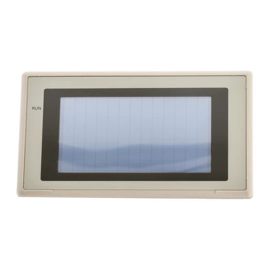
Page 25: Names And Functions Of Parts
Section Names and Functions of Parts Names and Functions of Parts Before starting operation, the names and functions of the parts of the NT21 are described here as a confirmation. A method of hardware settings is also de- scribed. Front View... - Page 26 Connect the cable for connection to the host or NT Support Tool here. A bar code reader can also be connected here. This is a 9-pin connector for RS-232C only. Note Before turning the power ON/OFF, confirm system safety, otherwise the system may operate unpredictably.
-
Page 27: Hardware Installation And Connections
This section describes the installation of the PTs and methods for connection to other devices. For details on connecting to the host, refer Section 4 Connecting to the Host from the RS-232C Port or Section 5 Connecting to the Host from the RS-422A/485 Port. -
Page 28: Installation
Installation Note On unpacking the NT21 check the external appearance and confirm that there is no damage. Also confirm that there is no abnormal noise on shaking the PT light- Installation Install the NT21 in the operation panel and connect the power to the NT21 as described below. -
Page 29: Power Supply Connection
Section Installation Fit the hook of the fitting in the square hole in the body and tighten the screw with the Philips head screwdriver while lightly pulling the fitting. Note 1. During work at the panel, do not allow any metal filings or wire strands to enter the NT21. -
Page 30: Connecting Link Adapters
Carry out wiring under the following conditions. 1, 2, 3... 1. In cases where the distance between the NT21 is short and it is assumed that there is no potential difference between grounds, ground as shown in Fig. (a) below. - Page 31 Section Connecting Link Adapters power to the Link Adapter through pin 6 of the RS-232C connector, so an exter- nal power supply is not required. Note 1. The RS-232C connector is not insulated from the RS-422A/RS-485 connec- tor within the NS-AL002 Link Adapter.
- Page 32 The NS-AL002 Link Adapter has a 4-pin DIP switch that sets the RS-422A/ RS-485 communication conditions. Set the DIP switch before connecting the communications cable. The following table shows the functions of the DIP switch pins. The factory de- faults are OFF for all 4 pins. Pin(s)
- Page 33 We recommend grounding the shield at one end, as shown in the following diagram.
-
Page 34: Connecting An Nt-Al001 Link Adapter
3-2-2 Connecting an NT-AL001 Link Adapter The NS-AL001 Link Adapter connects to serial port A or B of the NT21 with an RS-232C cable and converts the RS-232C communications to RS-422A or RS-485. (Serial ports A and B cannot be used simultaneously.) The NT21 supplies +5 V power (150 mA max.) to the Link Adapter through pin 6... - Page 35 Latch the hook (a) on the rear of the Link Adapter onto the top edge of the DIN Track, and pivot the Link Adapter downwards (b) as shown in the diagram below. Next, fit End Plates at the right and left of the Link Adapter to secure it so that it cannot shift laterally.
- Page 36 (4.33) 2-M4 holes (0.83) Units: mm (inch) Note The control panel must be at least 2 mm (5/64 inch) thick for a secure and strong mount. Specifications The following tables list the NT-AL001 Link Adapter’s general and communica- tions specifications.
- Page 37 500 m max. Terminal block configuration 8-terminal detachable terminal block, M3.0 DIP Switch Settings The NT-AL001 Link Adapter has a 6-pin DIP switch that sets the RS-422A/ RS-485 communication conditions. Set the DIP switch before connecting the communications cable. (Factory settings)
- Page 38 “RS/CS control” by turning ON either pin SW1-5 or SW1-6. Note 1. Do not turn ON both SW1-5 and SW1-6 at the same time. This may damage internal circuits. 2. The power supply to the device supplying +5 V must be turned OFF before starting wiring work.
- Page 39 When using RS-422A or RS-485 cables for long-distance communications, do Shield Connections not ground the shield at both ends of the communications line because large cur- rents can flow through the shield due to the difference in potential at the two...
-
Page 40: Connecting The Nt Support Tool
Connecting the NT Support Tool In order to install the system program in the NT21, or to transmit screen data created with the NT Support Tool to the NT21, the NT21 must be connected to a personal computer with an RS-232C cable. -
Page 41: Connecting A Bar Code Reader
3-7 Input of Numeric Values and Character Strings in the NT31/NT31C/ NT631/NT631C/NT21 Programmable Terminal Reference Manual. Note Make sure that the power supply to the bar code reader and the power supply to the PT are both OFF before connecting or disconnecting the cable. -
Page 42: Data Format
During bar code reading, the NT21 performs RS/CS control. When the Input Method setting of the NT21 is set to Auto, the RS signal is turned OFF, prohibit- ing the next input, until the read data is notified to the host. -
Page 43: Using A Memory Unit
One Memory Unit can store the screen data for two PTs. Note 1. Make sure that the power supply to the PT is OFF before connecting or dis- connecting a Memory Unit. After mounting a Memory Unit, be sure to tighten its two screws. -
Page 44: Installation Method
Mounting screws Screw hole 3-5-2 Method of Use As shown in the figure below, a Memory Unit has 2 four-pin DIP switches, and the operation is determined by the DIP switch settings at startup. Factory setting is turned all to OFF. - Page 45 Reference: When screen data is written to the Memory Unit, the data that has been stored in the specified Area up until that point is lost (if the data is written into only one Bank, the other Bank will not be affected).
- Page 46 NT21, this mode becomes conve- nient. Reference: When data is written to the NT21, the data that has been stored up until that point is lost. When the system program is changed, the operation of NT21 also chan- ges.
- Page 47 NT21. Transmission can be executed while checking the settings. Reference: When data is written to the NT21 or Memory Unit, the data that has been stored up until that point is lost.
- Page 48 S When transmitting the system program and screen data simultaneously from Reference: the PT to the Memory Unit, the setting of banks is Bank 0: system program, Bank 1: screen data, and when transmitting them from the Memory Unit to the PT, either of the following combinations must be used.
- Page 49 Memory Unit manual transmission screen by pressing the OK touch switch, but in the case of other errors, the status described above re- mains in effect until the NT21 power is turned OFF or reset.
-
Page 50: Connecting To The Host From The Rs-232C Port
SECTION 4 Connecting to the Host from the RS-232C Port This section describes how to connect the host directly to the NT21’s RS-232C port. Connecting to the RS-232C Port at the Host ........ -
Page 51: Connecting To The Rs-232C Port At The Host
1:N NT Link (page 60). 4-1-1 Host Types and Settings The types of host that can be connected to a PT by using the RS-232C ports of both devices, and the settings to be made at the host, are described here. - Page 52 *1: Use a CPM2C-CN111 or CS1W-CN114/118 Connecting Cable, CPM1-CIF01 RS-232C Adapter, or CPM1-CIF11 RS-422A Adapter to connect. *2: The CQM1H-CPU11 does not have a built-in RS-232C port, so connect to the PT at the peripheral port with a CS1W-CN118 Connecting Cable.
- Page 53 Level 1, 2, 3 Unit # *1 Set the Host Link baud rate at 9,600 bps or 19,200 bps with the memory switch at the NT21. For details, refer to Setting the Host Link Method (page 127). *2 The 1-to-N setting enables BCC (Block Check Character). It is not actually possible to connect more than one NT21 in a single Host Link.
- Page 54 Section Connecting to the RS-232C Port at the Host od, the I/O port selector switch on the front of the Unit must be set to RS-232C (the upper position). CPU Bus Unit Settings When connecting to a CVM1/CV-series Host Link Unit, set the following commu- nication conditions for the CPU Bus Unit settings.
- Page 55 Data length ASCII 7 bits Unit # *1 Set the Host Link baud rate at 9,600 bps or 19,200 bps with the memory switch at the NT21. For details, refer to Setting the Host Link Method (page 127). Either set PC Setup directly from a Programming Device (e.g., SYSMAC Sup- port Software), or transmit the PC Setup made at a Programming Device to the CPU Unit.
- Page 56 Connect to the CPU Unit’s built-in RS-232C port. • Connect to the CPU Unit’s built-in RS-232C port. C200HX/HG/HE(-Z)E • Connect to one of the RS-232C ports (port A or port B) on a Serial Communications Board. • Connect to the CPU Unit’s built-in RS-232C port.
- Page 57 Data length ASCII 7 bits Unit # *1 Set the Host Link baud rate at 9,600 bps or 19,200 bps with the memory switch at the NT21. For details, refer to Settings the Host Link Method (page127). Set the PC Setup settings directly from a Programming Device (e.g., the CX- Programmer Support Software).
- Page 58 CPM2C, it is necessary to select RS-232C or peripheral port connections, according to the kind of cable and port (on the cable) used, as shown in the fol- lowing table. Refer to the CPM2C Operation Manual for more details.
- Page 59 When using the CQM1H’s built-in peripheral port, turn ON SW7. Setting the Switches of a CPM2A When using a CPM2A, the switches on the front panel must be set as shown below in order to make the PC Setup settings effective.
- Page 60 *1 Set the Host Link baud rate at 9,600 bps or 19,200 bps with the memory switch at the NT21. For details, refer to Settings the Host Link Method (page 127). When the baud rate is set to 19,200 bps, the PC Setup of the CPU Unit need to be changed.
- Page 61 Section Connecting to the RS-232C Port at the Host Setting the Front Switches Set pins 4 and 5 of the CPU Unit DIP switch in accordance with the port that the NT21 is connected to. CS1G/H, CS1G/H-H ERR/ALM PRPHL/COMM SYSMAC CS1G...
- Page 62 Check the model and series of the PC against the model of CPU Unit before making the connections. The hosts that can be connected to the NT21 by the 1:1 NT Link using the RS-232C ports of both Units are indicated in the table below.
- Page 63 CPM2C, it is necessary to select RS-232C or peripheral port connections, according to the kind of cable and port (on the cable) used, as shown in the fol- lowing table. Refer to the CPM2C Operation Manual for more details.
- Page 64 Setting the DIP Switches on the Front of a C200HX/HG/HE(-Z)E, CQM1, CQM1H When using a C200HX/HG/HE(-Z)E, CQM1, or CQM1H, the DIP switches on the front panel must be set as shown below in order to make the settings in the PC Setup (data memory) effective. C200HX/HG/HE(-Z)E...
- Page 65 Connecting to the RS-232C Port at the Host Setting the Switches of a CPM2C When using a CPM2C, the switches on the front panel must be set as shown below in order to make the PC Setup settings effective. The settings for SW1 and SW2 depend upon the usage of the peripheral port and RS-232C port.
- Page 66 1:N NT Link using a CS1W-SCU21 or CJ1W-SCU41 Serial Communications Unit. Check the model and series of the PC as well as the model of Serial Commu- nications Board or Unit being used before making the connections. The hosts that can be connected to the NT21 by the 1:N NT Link using the RS-232C ports of both Units are indicated in the table below.
- Page 67 Setting the DIP Switches of a C200HX/HG/HE(-Z)E When using a C200HX/HG/HE(-Z)E, the DIP switches on the front panel must be set as shown below in order to make the settings in the PC Setup (in the DM Area) effective. RS-232C port communication condition setting Set pin 5 to OFF to make the settings made in PC Setup effective.
- Page 68 PT (0 – 7) *1 Set any value between 0000 and 0009 Hex for the communications baud rate. The same baud rate will be used regardless of the value as long as it is between 0000 and 0009 Hex.
- Page 69 Section Connecting to the RS-232C Port at the Host Setting the Front Switches Set pins 4 and 5 of the CPU Unit DIP switch in accordance with the port that the NT21 is connected to. CS1G/H, CS1G/H-H ERR/ALM PRPHL/COMM SYSMAC CS1G...
- Page 70 PT (0 – 7) *1 Set any value between 0000 and 0009 Hex for the communications baud rate. The same baud rate will be used regardless of the value as long as it is between 0000 and 0009 Hex.
- Page 71 = The largest model number of the 000j connected PT (0 – 7) When connecting PTs with model numbers 0, 2, 3, 4, and 5 to the built-in RS-232C port, for example, set 160 to 8200 Hex, CIO 161 to 000A Hex, and CIO166 to 0005 Hex.
- Page 72 Reference: When using the CX-Programmer to set the high-speed 1:N NT Link, set the com- munications baud rate to 115,200 bps. Setting the Front Switches Set pins 4 and 5 of the CPU Unit DIP switch in accordance with the port that the NT21 is connected to. CS1G/H, CS1G/H-H...
- Page 73 For example, when connecting PTs with model numbers 3, 4, 5, and 6 to port 1, set DM 32000 to 8200 Hex, DM 32001 to 000A Hex, and DM 32006 to 0006 Hex. Connecting to a CS/CJ-series Serial Communications Unit A CS-series Rack-mounted Unit: CS1W-SCU21 CJ-series: CJ1W-SCU41 (Port 2 is an RS-232C port.)
- Page 74 Link Method with RS-232 and an FA computer, etc. When connecting to the host in the memory link method, it is necessary to create a program for the memory link at the host side. The following are the communication conditions that can be used in the memory link method.
- Page 75 Connector Specification 9-pin ⇔ 9 pin XW2Z-S002 Note The cable’s tensile load is 30 N. Do not subject it to loads greater than this. Otherwise a discontinuity may occur, causing operation to fail. Wiring for a Host Link Applicable Units: C200H-LK201-EV1...
- Page 76 (9-pin type) – – – (25-pin type) * For Units that have a CTS setting selector switch, RS and CS do not have to be shorted if this switch is set to 0V. Wiring for Other Applicable Units: Connections CV500-LK201 (communication port 2)
- Page 77 Connecting to the RS-232C Port at the Host Compatible cables with attached connectors: XW2Z-200T (9-pin ⇔ 9-pin, 2 m) XW2Z-500T (9-pin ⇔ 9-pin, 5 m) CPU Units of CVM1/CV-series PCs without the suffix -EVj cannot be con- nected by any connection method. NT21 PC (Host Link Unit)
-
Page 78: Connecting To The Host From The Rs-422A/485 Port
SECTION 5 Connecting to the Host from the RS-422A/485 Port This section describes how to connect to the host using RS-422A/485 cable. Link Adapters convert communication signals between RS-232C cable and RS-422A/RS-485 cable. Connecting to the Host’s RS-422A/485 Port ........ -
Page 79: Connecting To The Host's Rs-422A/485 Port
NS-AL002.) • Method 3 This is a 1:N connection between the RS-232C ports on several PTs and the host’s RS-422A terminals (using RS-422A cable) through Link Adapters. The communications cable can be up to 500 m long with this method. -
Page 80: Host Types And Settings
(2 m max., not required with the NS-AL002.) Note One end of the wire must always be connected to the host (PC), and there must be no branching. Branching will cause problems such as transmission delays and communication failures. (Terminated) - Page 81 Settings at the Host When using the RS-422A type Host Link method, the settings shown below must be made at the host (depending on the Unit, some of these settings may not be necessary, or settings not shown here may be necessary).
- Page 82 Section Connecting to the Host’s RS-422A/485 Port *1 Set the Host Link baud rate at 9,600 bps or 19,200 bps with the Comm. Speed memory switch at the NT21. For details, refer to Setting the Host Link Method (page 125).
- Page 83 1-to-N Command level Level 1, 2, 3 *1 Set the Host Link baud rate at 9,600 bps or 19,200 bps with the Comm. Speed memory switch at the NT21. For details, refer to Setting the Host Link Method (page 125).
- Page 84 Data length ASCII 7 bits Unit # *1 Set the Host Link baud rate at 9,600 bps or 19,200 bps with the Comm. Speed memory switch at the NT21. For details, refer to Setting the Host Link Method (page 125).
- Page 85 S There are no Serial Communications Boards for the C200HX/HG/HE(-Z)E in Reference: which port B is the RS-422A port. S There are no Serial Communications Boards for the CQM1H in which port 1 is the RS-422A port. PC Setup Settings...
- Page 86 ASCII 7 bits Unit # *1 Set the Host Link baud rate at 9,600 bps or 19,200 bps with the Comm. Speed at the NT21. For details, refer to Setting the Host Link Method (page 125). Set the PC Setup settings directly from a Programming Device (e.g., CX-Pro- grammer).
- Page 87 CPM2C, it is necessary to select RS-232C or peripheral port connec- tions, according to the kind of cable and port (on the cable) used, as shown in the following table. Refer to the CPM2C Operation Manual for more details.
- Page 88 • The C200HX/HG/HE(-Z)E CPU Units can be connected by the RS-422A 1:1 NT Link method by installing a Serial Communications Board. • The CQM1H CPU Units can be connected by the RS-422A 1:1 NT Link method by installing a Serial Communications Board.
- Page 89 *3 CPU Units of CVM1/CV-series PCs without the suffix -EVj cannot be connected. The 1:1 NT Link method cannot be used using RS-485. To use the 1:1 NT Link method, connect by RS-422A. NT link connection using RS-422A/485 is not possible with the CPM1, CPM2A, and CPM2C.
- Page 90 *1 RS-422A port of the Serial Communications Board *2 RS-422A port of the Serial Communications Board For details on operations relating to the PC Setup, refer to the manual for the PC you are using. Setting the DIP Switches on a C200HX/HG/HE(-Z)E Serial Communica-...
- Page 91 Check the model and series of the PC against the CPU Unit model or Serial Communications Board before making the connections. The Units that can be connected as hosts to the NT21 by the 1:N NT Link method using a RS-422A/485 port are listed in the following table.
- Page 92 PTs (0 to 7) *1 Set any value between 0000 and 0009 Hex for the communications baud rate. The same baud rate will be used regardless of the value as long as it is between 0000 and 0009 Hex.
- Page 93 CPU Unit. After settings are written, they become effective by turning the power ON, restarting the Unit, restarting the communication port, or executing the STUP instruction. The following table shows the words allocated in the DM Area and the settings.
- Page 94 PTs (0 to 7) *1 Set any value between 0000 and 0009 Hex for the communications baud rate. The same baud rate will be used regardless of the value as long as it is between 0000 and 0009 Hex.
- Page 95 For example, when connecting PTs with model numbers 3, 4, 5, and 6 to port 1, set DM 32000 to 8200 Hex, DM 32001 to 000A Hex, and DM 32006 to 0006 Hex. Connecting to a CS-series Serial Communications Board...
-
Page 96: Direct 1:1 Connection To The Host's Rs-422A
PTs (0 to 7) For example, when connecting PTs with model numbers 3, 4, 5, and 6 to port 2, set DM 32010 to 8200 Hex, DM 32011 to 000A Hex, and DM 32016 to 0006 Hex. When using the Memory... - Page 97 A or B on the NT21. When an NS-AL002 Link Adapter is being used, the Link Adapter connects di- rectly to serial port B on the NT21, so an RS-232C cable is not required. Connecting the Link Adapter to the Host (RS-422A)
- Page 98 Section Connecting to the Host’s RS-422A/485 Port To avoid an FG ground loop, do not connect the functional ground of the Link Adapter to the shielding of the RS-422A cable. Wiring to one of the following Serial Communications Boards/Units • CS-series CS1G/H(-H) Serial Communications Board •...
-
Page 99: Direct 1:1 Connection To The Host's
A Link Adapter (NT-AL001 or NS-AL002) is required to convert communications methods between the RS-232C and RS-485 formats. Reference: RS-485 can be used between the Link Adapter and host only when the 1:N NT Link method (standard or high-speed) is selected at the host. -
Page 100: 1:N Connection To The Host's Rs-422A Port
Pins 5 OFF NS-AL002: All pins ON To avoid an FG ground loop, do not connect the functional ground of the Link Adapter to the shielding of the RS-485 cable. 5-1-4 1:N Connection to the Host’s RS-422A Port This section explains how to connect the RS-232C ports of two or more NT21s with the host’s RS-485 port through Link Adapters. - Page 101 (Turn ON pin 4 to enable the terminator in the last Unit.) terminator in the last Unit.) To avoid an FG ground loop, do not connect the functional ground of only one of the Link Adapters to the shielding of the RS-422A cable.
- Page 102 Pins 1 and 6 ON Pins 2 to 5 OFF NS-AL002: Pin 1 ON Pins 2 to 4 OFF To avoid an FG ground loop, do not connect the functional ground of the Link Adapter to the shielding of the RS-422A cable.
-
Page 103: 1:N Connection To The Host's Rs-485 Port
RS-485 port through Link Adapters. NS-AL002 Link Adapters are required to convert communications methods be- tween the RS-232C and RS-485 formats. S The RS-485 standard 1:N NT link method can be used only when the follow- Reference: ing Boards/Units are installed:... - Page 104 NT21 Host NS-AL002) (Total length 500 m max.) Wiring to one of the following Serial Communications Boards/Units • CS-series CS1G/H(-H) Serial Communications Board • CJ-series CJ1G Serial Communications Unit • C-series C200HX/HG/HE(-Z)E Serial Communications Board • CQM1H Serial Communications Board...
-
Page 105: Connecting To The Host's Rs-232C Port
Section Connecting to the Host’s RS-232C Port To avoid an FG ground loop, do not connect the functional ground of the Link Adapters to the shielding of the RS-485 cable. 5-1-6 Recommended Connectors, Cables and Crimp Terminals Connectors and Cables Recommended for RS-422A/485 When making an RS-422A/485 connecting cable, as far as possible use the rec- ommended parts indicated in the table below. -
Page 106: Host Types And Settings
Section Connecting to the Host’s RS-232C Port Note One end of the wire must always be connected to the host (PC), and there must be no branching. Branching will cause problems such as transmission delays and communications failures. (Terminated) Relay Terminal Block Relay Terminal Block Max. - Page 107 A or B on the NT21. When an NS-AL002 Link Adapter is being used, the Link Adapter connects di- rectly to serial port B on the NT21, so an RS-232C cable is not required. Connecting the NT21-side Link Adapters to the Host-side Link Adapter (RS-422A)
- Page 108 NS-AL002: Pins 1 to 3 ON Pin 4 OFF To avoid an FG ground loop, do not connect the functional ground of the Link Adapter at the NT21 to the RS-485 cable shielding. Connecting between the NT21-side Link Adapters (RS-422A)
- Page 109 Section Connecting to the Host’s RS-232C Port To avoid an FG ground loop, connect the functional ground of only one of the Link Adapters at the NT21 to the RS-422A cable shielding. Connecting between the NT21-side Link Adapters (RS-485) Link Adapters...
-
Page 110: Recommended Connectors, Cables, And Crimp Terminals
C200HX-CPU64-(Z)E C200HX-CPU65-ZE C200HX-CPU85-ZE Usable Cables with Attached Connectors: • For Host Link, 1:1 NT Link, or 1:N NT Link (+5 V power supplied from PC) XW2Z-070T-1 (9-pin to 9-pin, 0.7 m) XW2Z-200T-1 (9-pin to 9-pin, 2 m) SJ46006-102 (9-pin to 9-pin, 1 m) - Page 111 SJ46006-202 (Use when the PC has a +5 V output.) Note 1. The maximum tensile load of the recommended cable is 30 N. Do not ex- ceed this load. 2. After connecting a connecting cable, always tighten the connector screws.
-
Page 112: System Menu Operation
System Menu Operation This section describes the operation of the System Menu, focusing on the procedure to start the PT. Functions that are conve- nient when using the PT and those that are useful for system maintenance are also explained here. - Page 113 Section 6-12 Programming Console Function ..........
-
Page 114: System Menu Operation Flow
Create the Screen Data Create the data to be displayed on the NT21 by using the NT Support Tool. For details on creating screen data, refer to the NT-series Support Tool Ver. 4.6 for Windows Operation Manual (V061-E1-j). -
Page 115: Starting The Nt21
DIP switch settings (page 31). Screen Data and System If there is an error in the screen data stored in the NT21, an error screen is dis- Program Checks played. Pressing the OK touch switch on the error screen will return the display to that just before the error occurred. -
Page 116: Operation Modes And The System Menu
In addition, the NT21 also features the System Installer mode, which is used specifically for installing the system program. The System Installer mode is selected by operation at the panel when the NT21 power is switched ON. 6-3-1 Relationships among Modes The relationships among the System Menu, each of the operation modes, and the System Installer mode, are indicated in the figure below. - Page 117 Section Operation Modes and the System Menu Items in the System The items displayed in the system menu and their functions are as follows. Menu Menu Item Function Quit Clear the System Menu screen and return to the RUN mode screen.
-
Page 118: Menu Tree
For details on System Menu operations, refer to 6-3-3 Operations with the Sys- tem Menu (page 108). The menu tree may differ according to the system program installed in the NT21. The menu tree for the system program that is installed in the NT21 on shipment is shown below. SYSTEM INSTALLER MODE... -
Page 119: Operations With The System Menu
To suc- cessfully call the System Menu, first press a corner where no touch switch is dis- played, and then press any other corner regardless of the presence of a touch switch. - Page 120 Maintenance Mode in the System Menu. Press Maintenance Mode. Returning from the Return to the RUN mode by selecting Quit in the System Menu and other menus. System Menu to the RUN Mode Reference: The NT21 does not return to the RUN mode automatically if no operations are...
-
Page 121: Memory Initialization
Page 113 • Initializing recipe tables Page 117 Reference: If writing to the screen data memory is prohibited by the System Setting setting in the System Installer mode, memory initialization is not possible. 6-4-1 Clearing Screen Data Use this function if the screen data has been corrupted and the NT21 cannot be started up correctly. -
Page 122: Clearing Screen Data
On completion of screen data clearance, the NT21 returns to the MEMORY INIT. MENU screen. After the screen data has been cleared, if an attempt is made to set the NT21 to the RUN mode before screen data has been transmitted from the NT Support Tool or Memory Unit, an error message will be displayed and the RUN mode will not be established. -
Page 123: Initializing Display History Record Data
Use the display history record initialization function to clear the history record data to 0, for example when the screen data has been changed, etc. Also, if Dis- play History (Use Ring Buffer) under History Setting of System in PT Configura-... -
Page 124: Initializing Alarm History Record Data
The alarm history record function continually checks the status of host bits that have been designated in advance in the bit memory table, and records the time when any of the bits is set to 1 (comes ON), and the number of times that each bit comes ON. -
Page 125: Initializing The Memory Tables
PT Status Control Area from the host. For details, refer to 2-2-1 PT Status Control Area in the Reference Manual. S If the optional battery is not installed, the alarm history record data will be initial- ized when the PT’s power is turned OFF. - Page 126 NT21 power OFF and back ON again (page 140). S The bit memory table merely reflects the status of bits at the host and therefore cannot be initialized. S If the optional battery is not installed, the memory tables will be initialized when the PT’s power goes OFF even if the Resume Function memory switch is ON.
-
Page 127: Initializing The Memory Switches
Section Memory Initialization 6-4-5 Initializing the Memory Switches Initialization returns all the memory switches of the NT21 to their status on ship- ment. Initialize the memory switches by following the menu operations from the Main- tenance Mode Menu as shown below. -
Page 128: Initializing The Recipe Tables
NT Support Tool, you do not upload the data even once, initial- ization will restore the initial values set using the NT Support Tool. The values will not be cleared. Reference: If the optional battery is not installed, the recipe data will be initialized when the PT’s power is turned OFF. -
Page 129: Operations In The System Installer Mode
• Clearing screen data (page 121) 6-5-1 Calling the System Installer Mode If the NT21 has no system program installed, or if the system program is cor- rupted, the System Installer mode is automatically established when the power is switched ON. -
Page 130: Clearing/Installing The System Program
Operations in the System Installer Mode When it is necessary to install the system program or make settings for data management, press and hold the touch switch in the top left corner of the touch panel (size: 9 mm 9 mm) and turn ON the NT21. -
Page 131: Changing The System Settings
Transfer the screen data and proceed. Reference: If the new system program is not downloaded successfully after deleting a sys- tem program, it is not possible to use the NT21 at all. After deleting the system program, be sure to download a new one. -
Page 132: Clearing Screen Data
The settings remain as they were before the op- eration was started. • If writing of the settings fails, a screen asking whether you wish to try again is displayed. After the settings have been written, the System Installer mode menu screen is redisplayed. - Page 133 • If Return to Menu is selected, the NT21 returns to the MEMORY INIT. MENU screen without clearing the screen data. • If screen data clearance fails, a screen asking if you wish to try again is dis- played. On completion of screen data clearance, the NT21 returns to the System Install- er mode menu screen.
-
Page 134: Transmitting The Screen Data
• Image/library data • Recipe table data It is possible to transmit the screen data (data for all the screens) in file units, or to transmit individual data or the data of individual screens in data units. (It is not possible to transmit mathematical table data in data units.) - Page 135 • The power to the NT21 is interrupted. • The power to the personal computer on which the NT Support Tool is running is interrupted or the computer is reset. • The cable connecting the NT21 to the personal computer on which the NT Support Tool is running is disconnected or has a broken wire.
-
Page 136: Setting Conditions For Communications With Host By Using Memory Switches
• Screen data transmission is stopped by operation at the NT Support Tool. Note When transferring the data in units of screens, if there are changes in memory table and/or direct access, transfer such data along with the screen data. - Page 137 Combinations other than those indicated above cannot be set. Reference: When using serial port B for communication with the host, and serial port A for the transmission of screen data from the NT Support Tool, set the settings of serial...
-
Page 138: Setting The Host Link Method
Setting Conditions for Communications with Host by Using Memory Switches 6-7-2 Setting the Host Link Method Set the communication conditions for the host link method at serial port A or seri- al port B by following the menu operations from the Maintenance Mode Menu as shown below. - Page 139 Quit touch switch. The settings made last will be set and the NT21 will return to the MAINTENANCE MODE MENU screen. If the combination of settings for serial port A and serial port B is not allowed, an error message (indicating that the protocol settings are incorrect) will be dis- played when the Quit touch switch is pressed.
-
Page 140: Setting The 1:1 Nt Link Method
Quit touch switch. The settings made last will be set and the NT21 will return to the MAINTENANCE MODE MENU screen. If the combination of settings for serial port A and serial port B is not allowed, an error message (indicating that the protocol settings are incorrect) will be dis- played when the Quit touch switch is pressed. - Page 141 Section Setting Conditions for Communications with Host by Using Memory Switches The baud rate determines whether the 1:N NT Link is standard or high-speed. Standard: Standard 1:N NT Link High-speed: High-speed 1:N NT Link Select Memory Switch. Display the fourth memory switch screen by pressing the [↓] (next screen) or [↑] (previous...
- Page 142 • To confirm the settings and quit the memory switch setting screen, press the Quit touch switch. The settings made last will be set and the NT21 will return to the MAINTENANCE MODE MENU screen. If the combination of settings for serial port A and serial port B is not allowed, an...
-
Page 143: Setting The Memory Link Method
MENU screen with the previous settings still in effect. 6-7-5 Setting the Memory Link Method Set the communication conditions for the host link method at serial port A or seri- al port B by following the menu operations from the Maintenance Mode Menu as shown below. -
Page 144: Starting Operation
Quit touch switch. The settings made last will be set and the NT21 will return to the MAINTENANCE MODE MENU screen. If the combination of settings for serial port A and serial port B is not allowed, an error message (indicating that the protocol settings are incorrect) will be dis- played when the Quit touch switch is pressed. -
Page 145: System Settings
System initialization screen. Transmission of the Contents of Memory Tables If the Resume Function memory switch is set to ON, or if the initial values of the memory tables are used, the contents of the numeral/character-string memory tables are copied to the allocated words at the host. - Page 146 Section System Settings The following diagrams show how to display the memory switch setting screens and move between the screens. Select Maintenance Mode. Select Memory Switch. [ ] (next screen) [ ] (previous screen) (next screen) [ ] [ ] (previous screen)
-
Page 147: Setting The Start-Up Wait Time
The Start-up Wait Time is the time lapse until the NT21 switches to the RUN mode after it has been turned ON. Set this item if it takes some time for the host to start operation. Nothing is displayed during the Start-up Wait Time. -
Page 148: Setting The Buzzer Sound
6-9-4 Setting the Buzzer Sound The NT21 has a function for sounding a buzzer in response to a command from the host, or when an error occurs. It is possible to set whether or not the buzzer actually sounds with the memory switches. -
Page 149: Setting The Screen Saver Timer
S Do not turn ON the the “Battery Low Check” memory switch when a Battery is not installed. The battery low indicator will remain ON constantly. S Bit 13 (Battery Status) in the PT Status Notify Bits in the PT Status Notify Area will turn ON when the Battery voltage drops. -
Page 150: Setting The History Display Method
S If a battery is installed, the contents of the history record will be retained even when the NT21 is turned OFF, but the data will be lost if the battery fails and the NT21 is turned OFF. -
Page 151: Setting The Resume Function (Battery Required)
The NT21 has a function to retain the contents of the memory tables even when the power to the NT21 is OFF and write back them to the host when the power is turned ON. The optional battery must be installed to use the resume function. -
Page 152: Setting The Automatic Reset Function
[ ] (previous screen) touch switch, then make the setting. • To confirm the settings and quit the memory switch setting screen, press the Quit touch switch. The settings made last will be set and the NT21 will return to the MAINTENANCE MODE MENU screen. -
Page 153: Setting The Time-Out Interval
[ ] (previous screen) touch switch, then make the setting. • To confirm the settings and quit the memory switch setting screen, press the Quit touch switch. The settings made last will be set and the NT21 will return to the MAINTENANCE MODE MENU screen. - Page 154 [ ] (previous screen) touch switch, then make the setting. • To confirm the settings and quit the memory switch setting screen, press the Quit touch switch. The settings made last will be set and the NT21 will return to the MAINTENANCE MODE MENU screen.
-
Page 155: Setting The Bar Code Reader Input Function
3-7 Input of Numeric Values and Character Strings in the Reference Manual. S The bar code reader is connected to serial port A. This means that serial port B must be used for communications with the host. - Page 156 Press Quit. Pressing Abort on the communication condition/confirmation method setting screen causes the NT21 to return to the memory switch setting screen (4/4) with- out executing setting (with the previous settings still effective). On completion of communication condition/confirmation method setting, the...
- Page 157 [ ] (previous screen) touch switch, then make the setting. • To confirm the settings and quit the memory switch setting screen, press the Quit touch switch. The settings made last will be set and the NT21 will return to the MAINTENANCE MODE MENU screen.
-
Page 158: System Maintenance
The NT21 has a clock function that displays the date and time. When the NT21 is in RUN mode, it regularly reads the clock data from the speci- fied area in the host and stores that data in numeral memory table entries 247 to 253. - Page 159 Section 6-11 System Maintenance Display clock data by following the menu operations from the System Menu as shown below. Select Maintenance Mode. Select Calendar Check. Press Quit The NT21 will return to the MAINTENANCE MODE MENU screen.
-
Page 160: Checking The Pt Setting Status
Screen Configuration and Display Contents There are four different screens that show the PT setting status. Select the Down Arrow or Up Arrow as shown below to go to the next or to the previous screen. The display methods and contents are shown below. -
Page 161: Displaying The Display History Record
S Install an optional battery in the NT21 when using the display history record Reference: function. S When a battery is not installed or the battery fails, the contents of the history record will be unpredictable when the NT21 is turned OFF and will be initial- ized. -
Page 162: Displaying The Alarm History Record
The alarm history record function is a function that continually monitors during operation, the status of bits at the host designated in advance with bits in the bit memory table, and records the time when these bits come ON, and the number of times they come ON. - Page 163 S Install an optional battery in the NT21 when using the alarm history record Reference: function. S When a battery is not installed or the battery fails, the contents of the history record will be unpredictable when the NT21 is turned OFF and will be initial- ized.
-
Page 164: Checking Screen Data
The NT21 allows the registered screens (Nos. 1 to 3999) to be displayed and checked by operation from the System Menu. S Window screens cannot be displayed by operation from the System Menu. Reference: S Only the user screens (Nos. 1 to 3999) can be displayed. Screens for system use cannot be displayed. - Page 165 Setting Item Function Options Display of Lamp/ Allows designation of whether the bit number of the lamp bit set for a lamp or touch ON, OFF* Touch SW No. switch is displayed or not. The display format is as follows Ljfffffff (j: area type, fffffff: bit number).
- Page 166 Section 6-11 System Maintenance Displaying the SCREEN Display the SCREEN DATA CHECK screen by following the menu operation DATA CHECK Screen from the System Menu shown below. Select Maintenance Mode. Select Screen Data Disp. Use the numerical input switches to input the number of the screen to be displayed.
-
Page 167: Device Check
Start Confirmation Stop Confirmation Error Occurrence If you wish to continue by checking another screen, repeat the operation, start- ing by specifying the screen number. To end the operation, press Quit on the screen number selection screen. The NT21 returns to the MAINTENANCE MODE MENU screen. - Page 168 Select Device Check. Checking the Buzzer Check if the buzzer sounds correctly. Reference: The buzzer will sound in this check regardless of the setting made with the Buzz- er Sound memory switch. Select Buzzer Check. Check the buzzer by following the menu operations from the Device Check Menu as shown below.
- Page 169 On completion of the display and clearance of all dots, the NT21 returns to the DEVICE CHECK MENU screen. • To abort the LCD check, press the top right corner of the touch panel. The NT21 will return to the DEVICE CHECK MENU screen.
- Page 170 Check if the screen data memory is functioning normally. Check S In the screen data memory check, a write test is performed on the screen data Reference: memory. Since all the screen data in the NT21 is lost in this check, confirm that the data has been backed up at the NT Support Tool or Memory Unit before executing it.
- Page 171 A touch switch is normal if it is dis- played in reverse video while pressed. To end the check, press the touch switch at the top right corner, which is dis- played in reverse video. The NT21 will return to the DEVICE CHECK MENU.
-
Page 172: Checking Interfaces
Section 6-11 System Maintenance After confirming the result of the check, press Quit. The NT21 returns to the DE- VICE CHECK MENU screen. Note If a battery is installed and low battery voltage is detected, replace the battery immediately. For details on the replacement method, refer to 7-3-1 Replacing the Battery (page 184). - Page 173 • If communication with the NT Support Tool is normal, data transmitted from the NT Support Tool is displayed as hexadecimal data when received by the NT21. After confirming the result of the test, press Quit. The NT21 returns to the I/F CHECK MENU screen.
- Page 174 Press Execute to start the check. The data for checking communication is sent to the host, and is displayed as the Sending Data in hexadecimal. • If communication with the host is normal, the reply from the host is displayed at Received Data in hexadecimal.
- Page 175 The check is started as soon as the check screen is displayed. Send the com- mand from the host. • If communication with the host is normal, the data received from the host is dis- played in hexadecimal text code at Received Data.
-
Page 176: Programming Console Function
Select Comm. Port A or Comm. Port B. The check screen is displayed (Check screen, page 163). After confirming the result of the check, press Quit. The NT21 returns to the I/F CHECK MENU screen. 6-12 Programming Console Function The NT21 has been equipped with a Programming Console function, which al-... - Page 177 Section 6-12 Programming Console Function Note When the Programming Console function is used, carefully check that the sys- tem is safe before carrying out the following operations. Otherwise the system may operate unpredictably. • Changing monitor data • Switching the operating mode •...
-
Page 178: Compatible Systems
Section 6-12 Programming Console Function 6-12-1 Compatible Systems The Programming Console function can communicate with the PC with the com- munication methods indicated in the following table. Communication Applicable PCs Connected Port Method (*1) C200HE-CPU42-(Z)E (*1) C200HG-CPU43-(Z)E (*1) C200HG-CPU63-(Z)E (*1) -
Page 179: Connection Method
C200HX/HG/HE PCs of the following lot numbers. CPM1: jjj5, jj*6 where * is a number in the range 1 to 9 or the letter X or Y. CQM1: jjj3, jjj4, jjj5, jj*6 where * is a number in the range 1 to 9 or the letter X or Y. -
Page 180: Method Of Use
Reference: When an error screen is displayed, press the Check touch switch on the screen to return to the system menu. In addition, pressing two of the four corners of the touch panel simultaneously in the error screen enables the display of the system menu. - Page 181 However, since there is a discrepancy between the size of the displayed keys and the size of the touch switches, take care to press as close to the center of the key as possible by referring to the figure below.
-
Page 182: Version Display
Programming Device. • It is not possible to adjust the volume of the key press sound. Whether or not the key press sound sounds is determined by the setting for the Key Press Sound memory switch of the NT21. -
Page 183: Method Of Use
After checking the version information, press the Quit touch switch to exit the Version Display screen and return to the Expansion Mode screen. S The PT model always shows the model number of the ivory model of the PT. Reference: The B suffix will not be displayed, even for black models. - Page 184 SECTION 7 Troubleshooting and Maintenance This section describes the action to take when errors occur in the PT, and how to carry out maintenance and inspection to prevent the occurrence of errors. Troubleshooting ............
-
Page 185: Troubleshooting
Section Troubleshooting Troubleshooting When a fault relating to the operation of the NT21 occurs, find the symptoms in the table below and respond by following the corresponding Remedy indicated in the table. Note 1. Confirm system safety before turning the power ON/OFF. - Page 186 Reference Manual. Create the screen data again The total of the element coefficients and then transmit all of the screen data in a batch to for the displayed screen is greater the NT21. than 1024.
-
Page 187: Responding To Displayed Error Messages
Remedy indicated in the table. For details of the error messages displayed when using Memory Unit and corrective action to take for them, refer to 3-5 Using a Memory Unit in page... -
Page 188: Errors Occurring At Start Of Operation And Their Remedies
Responding to Displayed Error Messages 7-2-1 Errors Occurring at Start of Operation and Their Remedies The table below shows the errors that can occur when the power to the NT21 is turned ON and when operation starts, and their remedies. - Page 189 B are Communication Method Settings on page Invalid Comm. Method mismatched. 126 and set the protocol of serial port A and serial port B so that their settings are matched. * Set serial port A to None when connecting the NT Support Tool and the host at the same time.
-
Page 190: Errors Occurring During Operation And Their Remedies
Section Responding to Displayed Error Messages 7-2-2 Errors Occurring during Operation and Their Remedies The table below shows the errors that can occur during operation of the NT21 and their remedies. Message Cause Remedy [Address Setting Error] The host side allocated words... -
Page 191: Errors Occurring On Screen Data Initialization And Transmission
Responding to Displayed Error Messages 7-2-3 Errors Occurring on Screen Data Initialization and Transmission The table below shows the errors that can occur when the NT21 data is initial- ized, and during data setting and transmission, and their remedies. Message... -
Page 192: Errors In The System Installer Mode And Their Remedies
Operation When When an error message is displayed, press the OK touch switch displayed on Communication Errors the screen. The NT21 will return to the screen that was displayed before the er- Occur ror occurred, and operation will restart. Display of... - Page 193 • Time out error • Data over flow error • PC unit number error (host link only) • NAK received (in the case of the host link, the end code is also displayed) • Undefined command error Send Errors The following errors can occur when receiving data.
-
Page 194: Maintenance Of The Nt21
Backing Up Screen Data Always back up the screen data and store it in a safe place in case a problem develops and the NT21 needs to be replaced or repaired. Preparing a Spare PT... -
Page 195: Installing Or Replacing The Battery
NT21 is shipped from the factory.) The battery life is about 5 years if the NT21 is used in a location where the ambi- ent temperature is 25_C. If the temperature at the location of use is higher than this, the battery life will be shorter. -
Page 196: Inspection And Cleaning
Cleaning Method If the display is dirty the screen is difficult to see. Clean the screen from time to time as follows. • In daily cleaning, wipe the display with a soft dry cloth. If the soiling is particular- ly heavy, attempting to remove it by wiping with a dry cloth may damage the front sheet of the Unit. - Page 197 S After replacement, check that the new NT21 is not subject to the same error. S If a faulty Unit is returned for repairs, write as detailed a description of the fault as possible and send this description together with the Unit to the OMRON ad-...
-
Page 198: A Specifications
D-type grounding (Ground to 100 Ω or less) Grounding International standards UL, cULus, EC directives, C-Tick Class 1 Division 2 * The NT21 may not be used at a location where it is exposed to splashing oil for a long period. - Page 199 Note When using the +5 V output of pin No. 6, check that the total current required by the devices connected to ports A and B is less than 150 mA. The NT21 supplies +5 V "5% (150 mA max.) to pin 6 of these ports.
- Page 200 ON (1). Resume function Retains the contents of the numeral and character string memory tables (i.e., they are not initialized) when the NT21 is turned ON or the operation mode is changed. (Operates only when the optional battery is installed.) Setting: Set “ON”...
- Page 201 1:1 to 8 Transmission distance Max. 15 m * NT-AL001 or NS-AL002 Link Adapters are required to connect two or more PTs. When using Link Adapters, the specifications are as follows: • RS-232C cable: Max. 2 m (Not required with the NS-AL002)
- Page 202 1:1 to 8 Transmission distance Max. 15 m * NT-AL001 or NS-AL002 Link Adapters are required to connect two or more PTs. When using Link Adapters, the specifications are as follows: • RS-232C cable: Max. 2 m (Not required with the NS-AL002) •...
-
Page 203: B External Dimensions And Mounting Dimensions
Appendix B External Dimensions and Mounting Dimensions 178 (7.01) Mounting panel Mounting fixture 15.5 (0.61) (0.18) 142 (5.59) 190 (7.48) Units: mm (inch) - Page 204 Appendix B External Dimensions and Mounting Dimensions Cable Connection Dimensions 39.5 (1.56) 19.5 (1.77) (0.77) 58.3 (2.30) 72.6 (2.86) 52.5 (2.07) Units: mm (inch) 39.5 19.5 (1.56) (0.77) 43.6 (1.72) 52.5 (2.07) 72.6 (2.86) Units: mm (inch)
-
Page 205: C Transporting And Storing The Nt21
Appendix C Transporting and Storing the NT21 • When transporting the NT21, use the packaging intended for it. • When storing the NT21, observe the following conditions. Storage ambient temperature: –20 to 70_C Storage ambient humidity: 0 to 40_C: 40 to 50_C:... -
Page 206: D Making The Cable
Also refer to this procedure for making a connecting cable for use with RS-422A/485 type connections. Cable Preparation The preparation of the cable differs according to whether or not the shielding wire is to be connected to the FG. Cable with Shield Connected to FG 1, 2, 3... - Page 207 Soldering iron Heat-shrink tube (F, 1.5 mm dia., = 10 mm) 4. Push the heat shrink tube over the soldered joint and heat the tube to shrink it in place. Heat-shrink tube Hood Assembly Assemble the connector hood as shown below.
-
Page 208: E Making The Cable For Connecting A Personal Computer
Refer to the following when making a cable for connecting the NT Support Tool. Assembly of Connecting Cables Wiring should be carried out in one of the following ways, depending on the type of RS-232C connector. 25-pin Connector Personal computer... - Page 209 Connector and Connector hood Cable AWG28 5P IFVV-SB Multi-core shielded cable, made by Fujikura Ltd. CO-MA-VV-SB 5P 28AWG Multi-core shielded cable, made by Hitachi Cable, Ltd. * One XM2S-0911 (for PT) and either one XM2S-0911 or -0913 (for your personal computer) are needed.
-
Page 210: F Model List
Model Specification Applicable PC CS1W-SCU21 RS-232C (2 ports) CS-series Rack-mounting Unit CS1G/H, CS1G/H-H CJ1W-SCU41 Features an RS-422A/485 port (port 1) and an RS-232C port CJ-series (port 2). CJ1G CPU Units for Connection via Host Link Model Specification PC Type CPM1-10CDR-j... - Page 211 Features a connector for RS-232C connections (9-pin) CS-series, high-speed CS1H-CPU64H CS1H-H CS1H-CPU65H CS1H-CPU66H CS1H-CPU67H CJ1G-CPU44 Features a connector for RS-232C connections (9-pin) CJ-series CJ1G-CPU45 CJ1G CVM1-CPU01-EV2 Features a connector for RS-232C connections CVM1/CV-series CVM1-CPU11-EV2 (selectable/9-pin) CVM1 CVM1-CPU21-EV2 * One of the Serial Communications Boards C200HW-COM02/COM04/COM05/COM06-EV1 is required.
- Page 212 CVM1-CPU01-EV2 Features a connector for RS-232C connections CVM1/CV-series CVM1-CPU11-EV2 (selectable/9-pin) CVM1 CVM1-CPU21-EV2 * One of the Serial Communications Boards C200HW-COM02/COM04/COM05/COM06-EV1 is required. CPU Units for Connection via 1:N NT Link Model Specification PC Type (*1) CQM1H-CPU51 Features a 9-pin connector for RS-232C connections...
- Page 213 Reference: Serial Communications Boards (CS1W-SCB41) and Serial Communications Units (CS1W-SCU21) with lot number 991220 (12/20/99) and later support the high-speed 1:N NT Link. Boards and Units with earlier lot numbers cannot be used to establish a high-speed 1:N NT Link.
- Page 214 Links the RS-232C port of a NT21 and the peripheral port of a CPM1, CPM2A, CPM2C, SRM1 (compatible with host link, and NT Link (1:1)) CPM1-CIF11 Links the RS-422A port of a Link Adapter and the peripheral port of a CPM1, CPM2A, CPM2C, SRM1 (compatible with host link) Related Parts and Equipment for PT...
-
Page 215: G Option List
Attached to the display to prevent irregular reflection or contamination. The entire sheet is colorless and transpar- ent. The five sheets make a set. Chemical-resistant Covers ... NT20S-KBA01 Covers the front panel and protects it from various chemical agents. The entire sheet is milky white and made of silicone rubber. - Page 216 Memory Unit ... NT-MF261 This is a special unit for reading/writing the screen data and the system programs in an NT21. Data is transmitted by DIP switch setting at the Memory Unit.
-
Page 217: Index
Clearing/installing the system program, 119 Effective display area, 188 clock, displaying the date and time, 147 Enclosure ratings, 187 Comm. A Method, 125 Error messages, 176 Comm. B Method, 125 Errors in the system installer mode and their remedies, 181... - Page 218 Life expectancy (display panel), 188 Power supply connection, 17 Life expectancy (touch panel), 188 precautions, xi Link Adapters, RS-232C/RS-422A, 205 Precautions to be observed when transmitting screen data, 124 maintenance, 173 Programming Console function, 165 Maintenance Mode, 106 Programming environment, 189...
- Page 219 Support Tool, 205 Connecting the NT Support Tool, 28 Selecting menu items, 108 Switching from the System Menu to the RUN mode, 109 Serial Communication Board, 40, 55, 60, 69, 83 Switching to the RUN mode, 133 Serial Communication Unit, 40...
-
Page 220: Revision History
Revision History A manual revision code appears as a suffix to the catalog number on the front cover of the manual. Cat. No. V068-E1-01 Revision code The following table outlines the changes made to the manual during each revision. Page numbers refer to the previous version. - Page 221 Regional Headquarters OMRON EUROPE B.V. Wegalaan 67-69, NL-2132 JD Hoofddorp The Netherlands Tel: (31)2356-81-300/Fax: (31)2356-81-388 OMRON ELECTRONICS LLC 1 East Commerce Drive, Schaumburg, IL 60173 U.S.A. Tel: (1)847-843-7900/Fax: (1)847-843-8568 OMRON ASIA PACIFIC PTE. LTD. 83 Clemenceau Avenue, #11-01, UE Square,...
- Page 222 Authorized Distributor: Cat. No. V068-E1-01 Note: Specifications subject to change without notice. Printed in Japan...