Table of Contents
Advertisement
Quick Links
Advertisement
Chapters
Table of Contents

Related Manuals for Omron NT4S


Summary of Contents for Omron NT4S
- Page 1 Cat.No. V056-E1-1 NT4S/NT15S/NT18S Programmable Terminal OPERATION MANUAL...
- Page 3 NT4S/NT15S/NT18S Programmable Terminal Operation Manual Produced March 1999...
- Page 5 OMRON Product References All OMRON products are capitalized in this manual. The word ‘Unit’ is also capitalized when it refers to an OMRON product, regardless of whether or not it appears in the proper name of the product. The abbreviation ‘Ch,’ which appears in some displays and on some OMRON products, often means ‘word’...
-
Page 7: Table Of Contents
NT4S-SF121B-E ........ - Page 8 SECTION 6 Linking to OMRON Controllers ......OMRON Host-Link ............. .
-
Page 9: About This Manual
About this Manual: This manual describes the basic functions and operation procedures of the NT-series programmable terminal NT4S/NT15S/NT18S, its operations when connected to a PC or a Host, and includes the sections described below. Please read this manual carefully and be sure you understand the information provided before attempting to install and operate the NT-series programmable terminal NT4S/NT15S/NT18S. - Page 10 [Connecting the NT4S/NT15S/NT18S to PLC’s other than Omron.] NT4S/NT15S/NT18S Programmable terminal, multi-vendor connections (V058-E1- ) The NT4S/NT15S/NT18S can also be connected to other PLC’s then Omron only. This manual describes how to connect to other PLC’s.
-
Page 11: Precautions
PRECAUTIONS This section provides general precautions for using the Programmable Terminal. The information contained in this section is important for the safe and reliable application of the Programmable Terminal. You must read this section and understand the information contained before attempting to set up or operate a Programmable Terminal. -
Page 12: Intended Audience
Safety Conventions and their Meanings This operation manual uses the following conventions and symbols to indicate cautions, warnings, and dangers in order to esure safe use of the NT4S/NT15S/ NT18S. The caustions, warnings, and dangers shown here contain important information related to safety. - Page 13 Precautions The conventions used and their meanings are presented below. WARNING Indicates information that, if not heeded, could possibly result in loss of life or seri- ous injury. CAUTION Indicates information that, if not heeded, could result in relatively serious or minor injury, damage to the product, or faulty operation.
-
Page 15: The Terminals Of The Nt-Series
NT4S-SF121B-E ........ - Page 16 Display ..................1.7.1 NT4S-SF121B-E, NT4S-SF122B-E, NT4S-SF123B-E ........1.7.2 NT15S-SF121B-E .
- Page 17 Section 1 The Terminals of the NT-Series The Terminals of the NT-Series This manual is only valid for the following operating terminals: - NT4S-SF121B-E - NT4S-SF122B-E - NT4S-SF123B-E - NT15S-SF121B-E - NT18S-SF121B-E The terminals of the NT-series are the favourite Man-Machine-Interfaces for all applications, where an optimum relation of size to function is needed.
-
Page 18: Front View
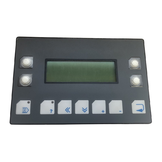
Section 1-1 The Terminals of the NT-Series Front View 1.1.1 NT4S-SF121B-E 1 Front Panel 11 Key Cursor Down 2 Front Cover 12 Key Cursor Left 3 Display 13 Status-LED Key Help 4 Status-LED Function Key (F3) 14 Key Help 5 Function Key (F3) -
Page 19: Nt4S-Sf122B-E
Section 1-1 The Terminals of the NT-Series 1.1.2 NT4S-SF122B-E 1 Front Panel 10 Key Scroll 2 Front Cover 11 Key Plus, Minus 3 Display 12 Key Enter 4 Function Key (F6) 13 Key Cursor Home 5 Status-LED Function Key (F6) -
Page 20: Nt4S-Sf123B-E
Section 1-1 The Terminals of the NT-Series 1.1.3 NT4S-SF123B-E 1 Front Panel 10 Key Enter 2 Front Cover 11 Key Clear 3 Display 12 Key Dot 4 Key Help 13 Keys 0 to 9 5 Status-LED Key Help 14 Key Cursor Home... -
Page 21: Nt15S-Sf121B-E
Section 1-1 The Terminals of the NT-Series 1.1.4 NT15S-SF121B-E 1 Front Panel 13 Key Dot 2 Front Cover 14 Keys 0 to 9 3 Display 15 Key Help 4 Status-LED Data Release 16 Key Cursor Home 5 Status-LED Help 17 Key Cursor Right, Left, Up, Down 6 Status-LED Print 18 Key Acknowledge 7 Status-LED Acknowledge... -
Page 22: Keyboard
The stroke length is approxi- mately 0.5 mm. The terminals NT4S-SF122B-E and NT15S-SF121B-E are equipped with a key- board made of membrane keys. The stroke length is approximately 0.3 mm. The key area of each key is 16 × 16 mm. The keys are covered by an embossed polyester sheet which is resistant to environmental effects. -
Page 23: Editing Keys
Section 1-2 The Terminals of the NT-Series 1.2.1 Editing Keys Key: 0 and ( ) ˚ is used to edit data within the editor. If the system variable Shift or ShiftCase is programmed, the characters ( and ) and ˚ can be entered. Key: 1 and STU is used to edit data within the editor. -
Page 24: Control Keys
Section 1-2 The Terminals of the NT-Series Key: Plus and = can be used to enter positive values within the editor. In the increment editor, the variable value is incremented by 1. When the key is held down, the function is repeated at a rate of repetition that is automatically increased. If the system variable Shift or ShiftCase is programmed, the characters and = can be entered. -
Page 25: Function Keys
Keys: Function Keys F1 to F16 with status-LEDs for functional feedback. In stan- dard mode, the key functions can be freely assigned to a soft key functionality; either as direct keys for menu control or to activate a function in the controller. 1.2.4.1 Function Key Arrangement 1.2.4.1.1 NT4S-SF121B-E... -
Page 26: Nt4S-Sf122B-E
Section 1-2 The Terminals of the NT-Series 1.2.4.1.2 NT4S-SF122B-E 1.2.4.1.3 NT4S-SF123B-E... -
Page 27: Nt15S-Sf121B-E
Section 1-2 The Terminals of the NT-Series 1.2.4.1.4 NT15S-SF121B-E 1.2.4.1.5 NT18S-SF121B-E... -
Page 28: Slide-In Identification Strips For The Function Keys
Various labeling methods are recommended, depending on the number of termi- nals involved. Suitable labeling methods for: single terminal: labeling with an indelible pen small number of terminals: transparency with laser printing large number of terminals: identification strips printed according to customer’s needs 1.2.5.1 NT4S-SF121B-E 1.2.5.2 NT4S-SF122B-E... -
Page 29: Nt4S-Sf123B-E
Section 1-2 The Terminals of the NT-Series 1.2.5.3 NT4S-SF123B-E 1.2.5.4 NT15S-SF121B-E 1.2.5.5 NT18S-SF121B-E... -
Page 30: Rear View
Section 1-3 The Terminals of the NT-Series Rear View 1.3.1 NT4S-SF121B-E 1 Fastening Screw for Enclosure 10 User-Mode Switch 2 Mounting Bolts 11 Switch Assignment User-Mode Switch 3 Front Panel 12 Ground Screw 4 Name Plate 13 Sign for Ground Srew... -
Page 31: Nt4S-Sf122B-E
Section 1-3 The Terminals of the NT-Series 1.3.2 NT4S-SF122B-E 1 Fastening Screw for Enclosure 10 Warning Note 2 Female Connector X3 11 Pin Assignment Connector X1 3 Terminator Switch (RS485) 12 Switch Assignment Terminator 4 Connector X1 (Power Supply) Switch... -
Page 32: Nt4S-Sf123B-E
Section 1-3 The Terminals of the NT-Series 1.3.3 NT4S-SF123B-E 1 Mounting Bolts 10 Pin Assignment Female Connector X3 2 Fastening Screw for Enclosure 11 Female Connector X3 3 Front Panel 12 Fastening Screw for Female Connector X3 4 Rubber Sealing... -
Page 33: Nt15S-Sf121B-E
Section 1-3 The Terminals of the NT-Series 1.3.4 NT15S-SF121B-E 1 Front Panel 12 Pin Assignment Connector X4 (Parallel Outputs) 2 Fastening Screw for Enclosure 13 Switch Assignment Terminator Switch 3 Rubber Sealing 14 Terminator Switch (RS485) 4 Warning Note 15 Female Connector X3 5 Mounting Bolts 16 Pin Assignment Female Connector X3 6 Note for Battery... -
Page 34: Nt18S-Sf121B-E
Section 1-3 The Terminals of the NT-Series 1.3.5 NT18S-SF121B-E 1 Mounting Bolts 10 Terminator Switch (RS485) 2 Fastening Screw for Enclosure 11 Pin Assignment Female Connector X3 3 Front Panel 12 Fastening Screw for Female Connector X3 4 Rubber Sealing 13 Female Connector X3 5 Warning Note 14 Switch Assignment User-Mode Switch... -
Page 35: Mounting The Terminals
1 to 10 mm. The front panels permit sealed installation of the units in accordance with the IP65 degree of protection. The terminals - NT4S-SF123B-E - NT18S-SF121B-E - NT15S-SF121B-E have a circumferential groove milled into the rear side of the front plate, containing a rubber sealing. -
Page 36: Front Panel Dimensions
Section 1-4 The Terminals of the NT-Series 1.4.1 Front Panel Dimensions 1.4.1.1 NT4S-SF121B-E 1.4.1.2 NT4S-SF122B-E... -
Page 37: Nt4S-Sf123B-E
Section 1-4 The Terminals of the NT-Series 1.4.1.3 NT4S-SF123B-E 1.4.1.4 NT15S-SF121B-E... -
Page 38: Nt18S-Sf121B-E
The Terminals of the NT-Series 1.4.1.5 NT18S-SF121B-E 1.4.2 Side View, Mounting Depth 1.4.2.1 NT4S-SF121B-E 1 Front Panel 4 Mounting Surface Thickness 1 to 6 mm 2 Foam Sealing 5 Spring Lock Washer B3 DIN127 Form B 3 Press-In Threaded Bolt M3 x 9... -
Page 39: Nt4S-Sf122B-E
Section 1-4 The Terminals of the NT-Series 1.4.2.2 NT4S-SF122B-E 1 Front Panel 4 Threaded Pin DIN 914 M4 x 35 2 Foam Sealing 5 Mounting Bracket 3 Monting Surface Thickness 1 to 14 mm... -
Page 40: Nt4S-Sf123B-E
Section 1-4 The Terminals of the NT-Series 1.4.2.3 NT4S-SF123B-E 1 Front Panel 5 Spring Lock Washer B4 2 Circumferential Rubber Sealing DIN127 Form B 3 Press-In Threaded Bolt M4 x 16 6 Nut M4 DIN934 4 Mounting Surface Thickness 1 to 10 mm... -
Page 41: Nt15S-Sf121B-E
Section 1-4 The Terminals of the NT-Series 1.4.2.4 NT15S-SF121B-E 1 Front Panel 5 Spring Lock Washer B4 DIN127 2 Circumferential Rubber Sealing Form B 3 Press-In Threaded Bolt M4 x 16 6 Nut M4 DIN934 4 Mounting Surface Thickness 1 to 10 mm... -
Page 42: Nt18S-Sf121B-E
Section 1-4 The Terminals of the NT-Series 1.4.2.5 NT18S-SF121B-E 1 Front Panel 5 Spring Lock Washer B4 DIN127 2 Circumferential Rubber Sealing Form B 3 Press-In Threaded Bolt M4 x 16 6 Nut M4 DIN934 4 Mounting Surface Thickness 1 to 10 mm... -
Page 43: Panel Cutout
Section 1-4 The Terminals of the NT-Series 1.4.3 Panel Cutout 1.4.3.1 NT4S-SF121B-E 1 4 Holes with a Diameter of 3.5 mm 1.4.3.2 NT4S-SF122B-E... -
Page 44: Nt4S-Sf123B-E
Section 1-4 The Terminals of the NT-Series 1.4.3.3 NT4S-SF123B-E 1 6 Holes with a Diameter of 4.5 mm 1.4.3.4 NT15S-SF121B-E 1 8 Holes with a Diameter of 4.5 mm... -
Page 45: Pin Assignments
Section 1-5 The Terminals of the NT-Series 1.4.3.5 NT18S-SF121B-E 1 10 Holes with a Diameter of 4.5 mm Pin Assignments The operating terminals are equipped with a universal interface by default. This universal interface combines several interface standards within one physical con- nector. -
Page 46: Pin Assignment X1 Supply Voltage
Section 1-5 The Terminals of the NT-Series 1.5.1 Pin Assignment X1 Supply Voltage The supply voltage is connected via the connector X1. Connector in the terminal: 3-pin male connector strip Phoenix COMBICON MSTBV 2,5/3-GF Designation Function Signal Ground Supply Voltage 0 V 24 VDC Supply Voltage 24 VDC The supply voltage is connected via a plug-in 3-pin female connector strip. -
Page 47: Pin Assignment X3 Ser1 Tty / 20 Ma Current Loop
Section 1-5 The Terminals of the NT-Series 1.5.2 Pin Assignment X3 SER1 TTY / 20 mA Current Loop TTY / 20 mA current loop, passive Designation Channel Function SER1 Transmit Data, Positive Polarity SER1 Receive Data, Positive Polarity SER1 Receive Data, Negative Polarity SER1 Transmit Data, Negative Polarity TTY / 20 mA current loop, active... -
Page 48: Pin Assignment X3 Ser1 Rs485
Section 1-5 The Terminals of the NT-Series 1.5.3 Pin Assignment X3 SER1 RS485 The interface RS485 is suitable for point-to-point connections and multipoint con- nections. Termination for point-to-point connection: For operation with point-to-point connection the termination must always be acti- vated. -
Page 49: Pin Assignment X3 Ser1 Rs232C
Section 1-5 The Terminals of the NT-Series 1.5.4 Pin Assignment X3 SER1 RS232c Interface for communication with controller. Designation Channel Function Shield SER1 Shield SER1 Transmit Data SER1 Clear To Send SER1 Request To Send SER1 Receive Data SGND SER1 Signal Ground A shielded cable with stranding in layers (cable type LiYCY) and with a minimum cross-section of 0.25 mm... -
Page 50: Shield
Section 1-5 The Terminals of the NT-Series 1.5.6 Pin Assignment X4 Parallel Outputs Open-collector-outputs, which switch the positive potential, are used as parallel outputs. These outputs are suitable for direct control of PLC inputs. The outputs can be activated by means of function keys or the controller. The assignment of these functions is carried out in the programming software. -
Page 51: Display
If the display is damaged, do not swallow or breathe in the liquids or gases being emitted and avoid direct contact with skin. Danger of Poisoning! Could Result in Burns! 1.7.1 NT4S-SF121B-E, NT4S-SF122B-E, NT4S-SF123B-E Overview of the technical data: Type : LCD-Module... -
Page 52: Nt18S-Sf121B-E
Section 1-7 The Terminals of the NT-Series 1.7.3 NT18S-SF121B-E Overview of the technical data: Type : LCD-Module Resolution: 240 x 128 Dots Graphics Capability: Full Graphics Capability Backlight : LED-Backlight Background Colour : White Lines (Font Normal) : Characters/Line (Font Normal) : Character Matrix (Font Normal) : 6 x 8 Dots Character Matrix (Font Zoom) :... -
Page 53: Character Attributes
Section 1-7 The Terminals of the NT-Series 1.7.6 Character Attributes The characters of the fonts Normal and Zoom can be displayed with different attributes. Operating Terminal Normal Flashing Underlined Inverse NT4S-SF121B-E NT4S-SF122B-E NT4S-SF123B-E NT15S-SF121B-E NT18S-SF121B-E 1.7.6.1 Font Normal 1.7.6.2 Font Zoom... -
Page 54: Ascii Character Set Table
Section 1-7 The Terminals of the NT-Series 1.7.6.3 ASCII Character Set Table... -
Page 55: User-Mode Switch
Section 1-8 The Terminals of the NT-Series User-Mode Switch The user-Mode switch is placed at the side of the terminal NT4S-SF122B-E and at the rear side of all other terminals. User-Mode Switch 4 Switches 8 Switches NT4S-SF121B-E NT4S-SF123B-E NT4S-SF122B-E NT15S-SF121B-E NT18S-SF121B-E The switches S5 to S8 can be used by the operator as needed. -
Page 56: Battery
The battery provides a minimum life of 5 years, even under unfavourable operating conditions. If the battery is drained the system message ‘change battery’ is generated. A new battery is supported by OMRON EUROPE. Replacing the battery: The battery can be replaced while the operating voltage is connected to ensure that the message data and time setting are not lost. -
Page 57: Fuse
Section 1-11 The Terminals of the NT-Series 1.10 Fuse A semiconductor fuse is used to prevent damage to the operating terminal. Once the fuse has been activated, the device must be disconnected from the supply voltage to allow the semiconductor fuse to regenerate. With an ambient tempera- ture of 20 C, the regeneration takes about 20 seconds. -
Page 59: Technical Data
NT4S-SF121B-E ........ -
Page 61: Nt4S-Sf121B-E
Section 2-1 Technical Data Technical Data NT4S-SF121B-E Keyboard a Total of 11 Keys, Mechanical with Tactile Feedback Divided into 2 Control Keys 4 Function Keys with LEDs and Slide-in Identification Strips 1 Special Key without LED 2 Special Keys with LEDs... -
Page 62: Nt4S-Sf122B-E
Mounting Depth 43 mm without Connector Enclosure Zinc-Coated Steel Plate Total Weight Approx. 400 g NT4S-SF122B-E Keyboard a Total of 30 Keys, Membrane with Tactile Feedback Divided into 6 Control Keys 6 Function Keys with LEDs and Slide-in Identification Strips... - Page 63 Section 2-2 Technical Data Central Unit Z80-CPU, 10 MHz, Watchdog Timer, Real-Time Clock, Programmable Interface Parameters, Temperature Compensation of the Display, Adjustment of Contrast, Battery Monitoring, User Mode Switch Memory 256 Kbyte Flash Memory, Application Memory 256 kByte Flash Memory, Firmware 128 Kbyte stat.
-
Page 64: Nt4S-Sf123B-E
Section 2-3 Technical Data NT4S-SF123B-E Keyboard a Total of 30 Keys, Mechanical with Tactile Feedback Divided into 5 Control Keys 8 Function Keys with LEDs and Slide-in Identification Strips 2 Special Key without LED 2 Special Keys with LEDs 13 Editing Keys... -
Page 65: Nt15S-Sf121B-E
Section 2-4 Technical Data Environmental Test DIN40040 Operation Storage Code Letter - Temperature Code Letter - Humidity Degrees of Protection DIN 40050 Mechanical Degrees of Protection Front: IP65 Rear: IP20 Front Panel Aluminum, Black Anodized with Affixed Polyester Cover, Circumferential Sealing Around Rear of Front Panel 150.0 ×... - Page 66 Section 2-4 Technical Data Fuse Semiconductor Fuse Connection System Plug-in Type, via SubminD Female Connector Strip Supply Voltage 24 V Direct Voltage, Residual Ripple Max. 10% Minimum Voltage 19.2 V Maximum Voltage 30.2 V Typ. Power Consumption 0.4 A Peak Current (10 ms) 0.6 A Connected Load 10 W...
-
Page 67: Nt18S-Sf121B-E
Section 2-5 Technical Data NT18S-SF121B-E Keyboard a Total of 34 Keys, Mechanical with Tactile Feedback Divided into 5 Control Keys 12 Function Keys with LEDs and Slide-in Identification Strips 2 Special Key without LED 2 Special Keys with LEDs 13 Editing Keys Display Backlit LCD Module, 16 Lines with 40 Characters Each, Display Area 72 ×... - Page 68 Section 2-5 Technical Data Environmental Test DIN40040 Operation Storage Code Letter - Temperature Code Letter - Humidity Degrees of Protection DIN 40050 Mechanical Degrees of Protection Front: IP65 Rear: IP20 Front Panel Aluminum, Black Anodized with Affixed Polyester Cover, Circumferential Sealing Around Rear of Front Panel 190.0 ×...
-
Page 69: Operating Modes
SECTION 3 Operating Modes This section describes the two available operation modes, the standard mode and the transparant mode and indicates how to select the operation mode. Setting the Operating Mode .............. -
Page 71: Setting The Operating Mode
The operating mode can be set by means of the User-Mode-Switch. The terminals are factory-set to the standard mode of operation. The user-mode switch is accessible at the side of the terminal NT4S-SF122B-E and at the rear side of all other operating terminals. - Page 72 Section 3-1 Operating Modes The switches S5 to S8 can be used by the operator as needed. The switch positions are stored at initialization time and afterwards they can be overtaken to the controll- S1 S2 S3 S4 S5 S6 S7 S8 Function X Standard-Mode with PLC (delivery state) X Standard-Mode without PLC X Transparent-Mode with start and stop code...
-
Page 73: Standard Mode
SECTION 4 Standard Mode This section describes the standard operation mode in detail. This section contains all detailed informa- tion to understand all features of the terminal in order to make a terminal application. Setting the Operating Mode ..............Startup Process. - Page 74 4.6.3.7 Parallel Message System ........... . 4.6.3.8 Printer Control .
- Page 75 4.9.2 External Messages ..............4.9.2.1 Structure of an External Message .
- Page 76 4.17 Image of the Mask Number..............4.18 Image of the Mode Selector Switch .
-
Page 77: Setting The Operating Mode
Section 4-1 Standard Mode Standard Mode The standard mode is the mode of operation in which the terminals are most com- monly used and that provides the highest performance. In this mode of operation, the terminals act as intelligent peripheral devices for the controller by performing controlled pre-processing of the visualization data, thus completely relieving the connected controller of all operating tasks. -
Page 78: Startup Process
Section 4-2 Standard Mode Startup Process All LEDs in the terminal are initially lit when the power is applied. A system-test is then performed that includes testing and initialization of the modules in the oper- ating terminal. Various system and error messages may be output during this sys- tem-test. -
Page 79: Communication In The Standard Mode
Section 4-4 Standard Mode 4.2.1 Startup Process without a Valid User Description The system-test performed on the application memory will detect whether a mo- dule is missing, defective or of the wrong type. This is then indicated to the operator by the following message: If the memory test establishes that the right type of Flash memory is used but that it does not contain a valid user description, the Flash memory will be erased and the... -
Page 80: External Mask Selection
Section 4-4 Standard Mode 4.4.2 External Mask Selection Mask calls from the controller are handled in the same way as messages. This requires simply that 8000H is added to the desired mask number prior to transfer. When the same number is assigned to a mask and message, both the mask and the message are called up during external mask selections. - Page 81 Section 4-4 Standard Mode Up to eight different passwords with a length of up to 11 characters can be defined. When defining the passwords, the access authorizations should be entered in a hierarchical structure. Example: - password for the manufacturer of the system, machine, etc. - password for servicing on site - password for the machine setter, master craftsman, foreman etc.
- Page 82 Section 4-4 Standard Mode The Data Release key will have no function if pressed with an insufficient edit level. The password can be entered in any I/O mask. Note that the Setup Mask is an exception. The system variable MskchgPasswd is designed to prompt for pass- word entry.
-
Page 83: Reactivating The Password Protection
Section 4-4 Standard Mode 4.4.3.1 Reactivating the Password Protection The access authorization for a mask or variable is reset whenever - the operating terminal is switched off and turned back on - an incorrect password is entered - bit 2 in the Write Coordination Byte is set - the system variable MskchgResPasswd is activated... -
Page 84: Masks
Section 4-5 Standard Mode Masks In conjunction with the operating system, the term ‘mask’ always refers to the con- tents of one screen. The size of masks therefore varies from operating terminal to operating terminal. Masks with a specific functionality form the basic elements of the operator guid- ance. -
Page 85: Setup Mask
Section 4-5 Standard Mode 4.5.2.1 Setup Mask Only terminal-specific parameters can be defined in the Setup Mask. This is be- cause no communication takes place with the connected controller while the Star- tup Mask and Setup Mask are displayed. The external data release therefore has no function. -
Page 86: Variables
Section 4-5 Standard Mode 4.5.2.3 Password Mask The password mask is an I/O type of mask. The functionality is as illustrated in the password description. 4.5.2.4 I/O Mask As a basic type of mask, the I/O mask offers a broad range of functions - enough in fact for configuring complete operator guidances based entirely on it. -
Page 87: Output Variables
Section 4-6 Standard Mode 4.6.1 Output Variables Output variables are numerical or alphanumerical data stored in the memory of the connected controller. The variables are retrieved from the controller whenever re- quired, and output on the display at the programmed location according to the defined method of representation, formatting and scaling. - Page 88 Section 4-6 Standard Mode The output is in millimeters, so a conversion in the controller is not necessary. The following format has been selected in the variable definition: PLC address: Data type Word Variable type: Decimal number (without sign) Length: 6 digits Post-decimal places: 2 digits...
- Page 89 Section 4-6 Standard Mode Formula for Scaling the Output: Scaling is always performed on the variable in the operating terminal. Through scaling, the measured values collected in the controller are adapted to the operator guidance. The output representation is determined by formula 1 only. Unlike the factor and divisor, the summand (representing an offset) can be set to the value 0.
-
Page 90: Decimal Number' Representation
Section 4-6 Standard Mode 4.6.1.1 ‘Decimal Number’ Representation The decimal representation of numbers is the most frequently used representation method. The operating concept differentiates between the following decimal number types of representation: Standard, Timer, Counter and BCD-Format. Decimal representation includes integers and floating point numbers. 4.6.1.1.1 ‘Standard’... -
Page 91: Counter' Variable Type
Section 4-6 Standard Mode The command sequence LC T (Load current time value as a BCD-number) MW 200 now causes the current time value to be loaded into flag word 200. Before being output, the operating terminal reads this value as a BCD-coded time value and interprets it. -
Page 92: Bcd-Number' Variable Type
Section 4-6 Standard Mode 4.6.1.1.4 ‘BCD-Number’ Variable Type The BCD format is partially used to represent numbers in the PLC. This output is required in special cases. The positional significance of the displayed digits in- creases from right to left. The numbers 0 to 9 are used for the representation; leading zeros can be included optionally. -
Page 93: Selection Image' Representation
Section 4-6 Standard Mode Multiple-line selection texts are primarily used for menu control. Unlike one-line selection texts, multiple-line selection texts display the text list either in full or in part. If the value for the selection text field height is less than the number of text elements to be displayed, the cursor keys can be used to scroll through the text elements. -
Page 94: Floating Point Number' Representation
Section 4-6 Standard Mode The names for the images represent the images in the image list. The actual list will look something like this: This image list has been defined with four entries. The graphic selected by the controller will be displayed. All of the images in an image list should have the same output size to ensure that they overwrite (overlap) each other completely. -
Page 95: Binary Number' Representation
Section 4-6 Standard Mode 4.6.1.7 ‘Binary Number’ Representation The binary format permits the representation of single bits, bytes, words or Lwords. The value for the ‘length’ entered in the variable definition corresponds to the num- ber of bits to be represented. Counting always begins with bit 0. The number of blanks indicates how many gaps (spaces) are inserted between each bit. -
Page 96: Curve Representation (Trendline)
Section 4-6 Standard Mode Bar charts can be output once only, cyclically or after defined events (event-con- trolled). They are used purely to indicate actual values. The range of values for outputs extends from -32768 to +32767. If your mask contains several bars, you should address the variables such that they can be transferred contiguously. -
Page 97: Input Variables
Section 4-6 Standard Mode If you need a width of more than 54 pixels, you can output several curves directly adjacent to one another. Fig. 7: Example of a curve representation The height information, in other words the variable values, is read from the controll- er in a contiguous field by means of one read job. - Page 98 Section 4-6 Standard Mode Counter When writing to a counter variable, any scaling that may have been performed is first reversed. The BCD-coded value is then computed and transferred to the PLC. Avoid writing to a counter word in the PLC, as this has uncontrolled results on the control bits.
-
Page 99: System Variables
Section 4-6 Standard Mode 4.6.3 System Variables System variables can be used to control terminal-internal functions. System variables can be referenced to function keys and soft keys. They can also be used in masks as normal variables for input and output processes. The following applies if a system variable is linked to a function key or soft key: - do not link a change of mask function and a system variable to the same key - it is not necessary that the same function key or soft key is used to set (1) and... - Page 100 Section 4-6 Standard Mode UserVersion Indicates the version number of the project description to the operator. The user enters this number into the programming system during programming time. Data type: Numeric Editor: Output: Numeric, 3 digits Possible values: Boot This variable can be used to initiate the terminal to boot (system restart). The vari- able is suitable for integrating the setup function into the regular operator guidance, making it possible to modify terminal parameters which require a subsequent rein- itialization (system restart) in any I/O mask.
-
Page 101: Communication Ser1
Section 4-6 Standard Mode TurnOnTemp Is used to ensure that the liquid crystal display of the operating terminal is not turned on until a certain ambient temperature is reached. This variable is only rele- vant for operating terminals provided with a corresponding functionality in conjunc- tion with the corresponding display. - Page 102 Section 4-6 Standard Mode ComStopBitsA Defines the number of stop bits for the communication via SER1. Data type: Numeric Editor: Selection text , positive decimal number Output: Possible values: 1 bit 1.5 Bits 2 bits ComBaudrateA Defines the baud rate for the communication via SER1. Data type: Numeric Editor:...
-
Page 103: Error Statistics Ser1
Section 4-6 Standard Mode ComTimeout Specifies the monitoring period for SER1. The value (0) deactivates the timeout monitoring function. Data type: Numeric Editor: Positive decimal number Output: Possible values: Inactive Initial state (1 to 65535) Timeout monitoring active (time in ComRetryTimeout Specifies the period of time, in milliseconds, that the terminal allows to elapse after an attempt to establish a connection via SER1 failed, before making another at-... -
Page 104: Communication Ser2
Section 4-6 Standard Mode ComFrameCount Error counter for monitoring of framing errors on SER1 to the PLC. Is erased on every download. Data type: Numeric Editor: (Possible) Output: Positive decimal number Possible values: 0 to 65535 ComStatisticsTab The system variable points to the beginning of the protocol statistics table with 6 elements of 4 bytes each. - Page 105 Section 4-6 Standard Mode ComParityB Determines the creation of and check method for the parity bit for SER2. Data type: Numeric Editor: Selection text , positive decimal number Output: Possible values: No parity Odd parity Even parity ComStopBitsB Defines the number of stop bits on SER2. Data type: Numeric Editor:...
-
Page 106: Real-Time Clock
Section 4-6 Standard Mode Data type: Numeric Editor: Selection text , positive decimal number Output: Possible values: Inactive Initial state Active The data entered into the associated system variables are accepted as the new parameters. Active The data stored in the Flash memo- ry by the programming software are accepted as the new parameters. -
Page 107: Serial Message System
Section 4-6 Standard Mode RTCYear This variable is used to display and set the year. Data type: Positive decimal number Editor: Positive decimal number Output: Positive decimal number Possible values: 0 to 99 (only the year and the decade are influenced) RTCDayofWeek This variable is used to display and determine the day of the week. - Page 108 Section 4-6 Standard Mode ClearRepBuf Is used to erase the entire serial message buffer. Optionally direct control via func- tion keys, soft keys or Editor. If necessary, passwords or special masks should be implemented to control erasure of the message buffer. Data type: Numeric Editor:...
- Page 109 Section 4-6 Standard Mode RepoutAnzYear Determines the number of digits that is to be used to represent the year. Data type: Numeric Editor: Selection text , selection image, decimal Output: Possible values: year represented by 2 digits year represented by 4 digits RepoutRepText Is used to display the most current serial message.
-
Page 110: Parallel Message System
Section 4-6 Standard Mode 4.6.3.7 Parallel Message System RepmanSortCritP This variable indicates to the terminal the sorting criterion according to which the messages are to be displayed. The default value is defined in the user description. This variable can be adapted during editing processes at a later date. Data type: Numeric Editor:... - Page 111 Section 4-6 Standard Mode RepoutAnzYearP Determines the number of digits that is to be used to represent the year. Data type: Numeric Editor: Selection text , selection image, alphanumeric, binary, decimal, hexadecimal Output: Possible values: year represented by 2 digits year represented by 4 digits RepoutRepTextP The terminal uses this variable to display the most current message of the parallel...
-
Page 112: Printer Control
Section 4-6 Standard Mode 4.6.3.8 Printer Control StopPrint When the system variable is activated, the print process currently in progress is terminated. Data type: Numeric Editor: Selection text , positive decimal number, soft key, function key Output: Possible values: Initial state Terminate print process BlockPrint Upon activation of this system variable, the block selected in the message mask is... -
Page 113: Menu Control / Keys
Section 4-6 Standard Mode BlockPrintLong Upon activation of this system variable, the entire area selected in a message mask is printed in full length. The settings chosen at programming are ignored. Data type: Numeric Editor: Selection text , positive decimal number, soft key, function key Output: Possible values:... - Page 114 Section 4-6 Standard Mode TabLeft In tables, this system variable can be used to shift to the column on the left. Data type: Numeric Editor: Soft key, function key Output: Possible values: Initial state To the left by one column TabRight In tables, this system variable can be used to shift to the column on the right.
- Page 115 Section 4-6 Standard Mode Letters (Characters) Point : ? ! . Minus \ * / - Plus ( ) ˚ 0 Zero S T U 1 V W X 2 Three Y Z % 3 Four J K L 4 Five M N O 5 P Q R 6...
- Page 116 Section 4-6 Standard Mode KeyCursRight This system variable allows soft keys to be used as a Cursor right key. Data type: Numeric Editor: Soft key, function key Output: Possible values: Initial state Treat soft key as a Cursor right key KeyCursUp This system variable allows soft keys to be used as a Cursor up key.
- Page 117 Section 4-6 Standard Mode KeyDot This system variable allows soft keys to be used as a Decimal point key. Data type: Numeric Editor: Soft key, function key Output: Possible values: Initial state Treat soft key as a Decimal point key KeyClear This system variable allows soft keys to be used as a Delete key.
- Page 118 Section 4-6 Standard Mode Key3 This system variable allows soft keys to be used as the key 3 . Data type: Numeric Editor: Soft key, function key Output: Possible values: Initial state Treat soft key as the key 3 Key4 This system variable allows soft keys to be used as the key 4 .
- Page 119 Section 4-6 Standard Mode Key8 This system variable allows soft keys to be used as the key 8 . Data type: Numeric Editor: Soft key, function key Output: Possible values: Initial state Treat soft key as the key 8 Key9 This system variable allows soft keys to be used as the key 9 .
-
Page 120: Password
Section 4-6 Standard Mode 4.6.3.10 Password MskchgPasswd Is used to enter the password into a mask. Data type: Numeric, alphanumeric Editor: Alphanumeric Output: Possible values: 11 characters MskchgResPasswd Is used to erase the password currently entered; resets the access authorization. The access levels are reset on every power-up. -
Page 121: Recipes
Section 4-6 Standard Mode 4.6.3.11 Recipes SelectDSNr This variable contains the number of the active data set. To edit the variable, the associated Selection Text Editor must be used. Data type: Numeric Editor: Selection text Output: Positive decimal number Possible values: 0 to 250 SelectDSName This variable contains the name of the active data set. - Page 122 Section 4-6 Standard Mode DSDelete This variable can be used to delete the active data set. The first data set from the same recipe will become the new active data set. Data type: Numeric Editor: Selection text , positive decimal number, soft key, function key Output: Possible values:...
- Page 123 Section 4-6 Standard Mode DSDnloadState This variable can be used to monitor the data transfer to the controller. Data type: Numeric Editor: Output: Selection text Possible values: Initial state Request for data transfer issued, but not yet re- leased by the controller Data transfer active LoadDSName This variable contains the name of the last data set which has been transferred to...
- Page 124 Section 4-6 Standard Mode StartRestore This variable controls the download from the PC to the Terminal. Data type: Numeric Editor: Selection text Output: Possible values: Initial state The terminal switches to the ready-to-receive state The terminal terminates a transmission currently in progress.
- Page 125 Section 4-6 Standard Mode StartUpload This variable can be used to read, for the active recipe, a data set from the controller and to store it in the terminal. Data type: Numeric Editor: Selection text Output: Possible values: Initial state Variables are read individually from their speci- fied addresses Variables are read as a block from the buffer...
-
Page 126: Running Time Meter
Section 4-6 Standard Mode 4.6.3.12 Running Time Meter Counter1 Counter2 Counter3 Counter4 Counter5 Counter6 Counter7 Counter8 Is used in conjunction with the start/stop function of the associated bit as a running time meter. The counter is incremented while the bit is set. Data type: Numeric Editor:... -
Page 127: Loadable Font
Section 4-6 Standard Mode 4.6.3.14 Loadable Font ChrsetName Is used to display the current font name. The name of the font is limited to a maximum length of 8 characters. Data type: Alphanumeric Editor: Output: Possible values: (Standard) Display using terminal font (Font name) Display using own font 4.6.3.15 Maintenance User1... -
Page 128: Editors
Section 4-6 Standard Mode 4.6.3.16 Editors EditInvers Specifies if the inverse representation is to be used for the Editor for inputs. Data type: Numeric Editor: Output: Possible values: Normal representation Inverse representation EditEnter Specifies the behavior of the Editor when the Data Release key is pressed. Data type: Numeric Editor:... -
Page 129: Editors
Section 4-6 Standard Mode QuitMessage Acknowledges the system message that is currently displayed by the system vari- able Message. Data type: Numeric Editor: Output: Possible values: Initial state Acknowledge 4.6.4 Editors Various Editors are available in I/O masks for the various data types. With the term Editor, we refer to program parts designed to provide a convenient method of ed- iting input variables. -
Page 130: Decimal Number Editor
Section 4-6 Standard Mode Key Functions in the Numerical Editor Key: Cursor up Moves the cursor up on the display by one editable variable and selects it in the process. After the cursor reaches the editable variable at the top, the variable at the bottom is selected next. -
Page 131: Floating Point Number Editor
Section 4-6 Standard Mode The variable type BCD-Number has a special feature. The Editor for BCD-numbers is also referred to as the ‘Decade Switch’. With scaled variables, the value in the PLC changes by +1/-1, although the input value which is actually displayed also depends on the defined scaling factor! This means that special care must be taken whenever scaling is required. -
Page 132: Hexadecimal Editor
Section 4-6 Standard Mode 4.6.4.3 Hexadecimal Editor The Hexadecimal Editor permits inputs of hexadecimal values. The sign keys have a special function here. Since there are no alphanumerical keys, alphanumerical characters can be entered with the sign keys instead. Key Functions in the Hexadecimal Editor Keys: 1 to 9 Direct entry of numerical values Key: Plus... -
Page 133: Selection Text Editor
Section 4-6 Standard Mode 4.6.4.5 Selection Text Editor The Selection Text Editor offers texts contained in a text list for selection. Every text in a text list is assigned to a numerical value. In the case of input variables, the numerical value associated with the corresponding text is written to the PLC vari- able. - Page 134 Section 4-6 Standard Mode Functional Description: - Every row variable is read from the PLC again just before being released for editing. - Input and cyclic output variables in the table are also continuously updated. An exception to this is the row variable that is currently being edited. One-time output variables are updated whenever the mask is refreshed (for example, when the Help key is released) or whenever the table offset changes.
-
Page 135: External Data Release
Section 4-6 Standard Mode Key: Cursor down Shifts to the next mask variable if the cursor is located at a single variable or at the last row variable. Shifts to the next row variable if the cursor is located at a variable other than the last row variable. - Page 136 Section 4-6 Standard Mode Fig.10: Pulse diagram - external data release DR Key Data Release key EA-Bit Editing request bit in the Read coordination byte ED-Bit External data release in the Write coordination byte EZ-Bit Editing status bit in the Read coordination byte DF-LED Status LED in the Data Release key A flashing status LED in the Data Release key always indicates that no external...
-
Page 137: Plc-Handshake
Section 4-6 Standard Mode 4.6.6 PLC-Handshake Handshake handling: - If the terminal writes to a variable for which the PLC handshake option has been selected, the RA bit (refresh request bit) in the Read coordination byte will be set and data entry inhibited. - The PLC can now, for example, provide a new data set for other input variables. -
Page 138: Graphics
Section 4-6 Standard Mode 4.6.8 Modified Data The conditions that determine the transfer of modified data from the operating ter- minal to the controller are preset by the user in the variable definition. The following options are available, allowing the user to select the point of time at which the data are transferred: - with the Enter key (standard) - with the +/- keys or the Enter key (Incremental Editor) -
Page 139: Graphics On Operating Terminals
Section 4-7 Standard Mode By double-clicking the image in the programming system with the mouse, the serv- er program used to create the image is opened automatically and the image can be edited. The scope of functions available to design the images depends on the fea- tures provided by the server program. -
Page 140: Recipes
Section 4-8 Standard Mode Recipes Various logically related variables can be organized into units known as recipes. Unlike mask variables, recipe variables are not transferred to the controller imme- diately after being entered, but are stored in the terminal as data sets. These data sets are protected against power failure. -
Page 141: Structure Of A Recipe
Section 4-8 Standard Mode - The recipe itself (texts and variables) - Data sets with data set number, data set name and variable offset - I/O mask for the recipe - Recipe field in the mask - Recipe buffer (address for the data area in the controller) - Variable Data Set Number for Transfer from the Terminal - Variable Recipe Number for Transfer from the Terminal - Variable Data Set Number for Request from the Controller... -
Page 142: Selecting A Recipe
Section 4-8 Standard Mode 4.8.2.1 Selecting a Recipe All recipes are assigned a number from 1 to 250 when they are programmed. You can select a recipe as follows: - By means of a fixed assignment between the recipe and a mask. Whenever this mask is opened, the recipe window will contain the recipe that was specified when the mask was originally programmed. -
Page 143: Deleting A Data Set
Section 4-8 Standard Mode The destination data set becomes the active data set after it has been copied. After it has been copied, the name of the destination data set consists merely of blanks. A new name can be defined with the system variable ActDSName. 4.8.2.4 Deleting a Data Set Only the active data set can be deleted. - Page 144 Section 4-8 Standard Mode Start Transfer recipe and data set numbers to PLC Recipe release flag set ? Request to terminate by operator ? Set Data Set-Download- Active-flag Transfer dataset to controller transfer checksum Reset Data Set- Download-Active-flag Reset recipe and data set number Fig.
-
Page 145: Transfer From A Controller
Section 4-8 Standard Mode 4. Sets the Data Download Active bit in the Read coordination byte. This bit can be used by the controller to identify an incomplete data set transfer (communication interrupted, power failure). An incomplete transfer is, however, repeated the next time the terminal is booted. -
Page 146: Transferring Data Sets To / From A Pc
Section 4-8 Standard Mode - The PLC issues a request for a data set read process. For this process, the controller writes the recipe number and data set number (the same as those for the transfer to the controller on request by the controller) of the destination data set to the variable specified for this purpose. -
Page 147: Transfer From A Pc
Section 4-8 Standard Mode 4.8.4.2 Transfer from a PC The terminal is placed to the Ready-to-Receive state when the system variable StartRestore is set to 1. The data sets can then be sent by the PC. The terminal recognizes the end of the data set transfer automatically by analyzing the data it has received. - Page 148 Section 4-8 Standard Mode The following are elements of this language: Key words: S + two further letters. They normally appear at the beginning of a line. Example: SDW or SFA Decimal number: Any number of the digits 0-9, preceded by a negative sign when required.
-
Page 149: Printing Data Sets
Section 4-8 Standard Mode Data set variables: Key: SDW Parameters: Offset of the variables in the recipe, variable size in bytes, value of the variables (as a hexadecimal string) End of data set identifier: Key: SDE Parameters: none Explanations: Recipe Version Number: On creating or changing the recipe description in the programming system, this version number is increased automatically whenever the structure of the data sets has changed. -
Page 150: Message System
Section 4-8 Standard Mode 4.8.6 Memory Requirements for Storing Data Sets The RAM in the terminal that is not required by the system (approximately 110,000 bytes) is used to store messages as well as data sets that have been stored in the RAM. - Page 151 Section 4-9 Standard Mode for as long as the Help key is held down. If several system messages are pending at the same time, they will be displayed in order of their system numbers, whereby the system message number ‘1’ represents the highest display priority. The user has the option of editing system message texts with the programming software.
- Page 152 Section 4-9 Standard Mode System Message 1 ..‘Wrong format’ This text indicates that an attempt has been made to enter an invalid data format into a variable field of the Numerical Editor. For example, the number of pre-deci- mal places entered exceeds the setting specified in the user description.
- Page 153 Section 4-9 Standard Mode System Message 11 ..‘Interface in use’ SER2 is already being used by another print job. An attempt has been made to transmit different types of data to the printer at the same time (e.g. to print recipes and messages).
-
Page 154: Suppressing The Display Of System Messages
Section 4-9 Standard Mode System Message 24 ..‘Data set format’ The size or internal version identifier of a data set loaded from the PC to the terminal and the corresponding values in the programming software do not match. System Message 25 . - Page 155 Section 4-9 Standard Mode ..This message is generated for all types of pro- tocol and interface errors. The error codes (CODE X) and SUBCODE (X) are protocol-spe- cific and are listed in the respective application documentation.
- Page 156 Section 4-9 Standard Mode ..The mode selector switch S4 was at the ‘on’ position when the supply voltage for the termi- nal was switched on. The Flash data will be re- tained if the following instructions are complied with.
- Page 157 Section 4-9 Standard Mode ..A self-test is performed when the terminal is switched on. This error message is generated if a key is pressed while the keyboard is being checked. Please release the key. If this mes- sage appears when no key is pressed, the message indicates a defective keyboard! .
- Page 158 firm- ware level and the hardware version and con- tact OMRON EUROPE B.V., Wegalaan 67-69, NL-2132 JD Hoofddorp, Tel.: +31 23 56 81 300..An unexpected interrupt has occurred. Make a...
- Page 159 Section 4-9 Standard Mode ..The user description stored in the FLASH con- tains errors. This error may occur at the end of a transmission, e.g. if the transmission is not complete or after a terminal is switched on that has a defective memory.
-
Page 160: External Messages
Section 4-9 Standard Mode 4.9.2 External Messages External messages are generated by the connected controller and forwarded to the operating terminal as information on the monitored process. The user can choose two separate message systems. Depending on the requirements, message trans- fers to the operating terminal can be either serial or parallel, regardless of whether the messages are process or fault messages. -
Page 161: Message Buffer Size
Section 4-9 Standard Mode 4.9.2.1.2 Message Buffer Size The total message buffer size is designed for management of up to 3000 mes- sages. Such a large number of data requires a corresponding computing capacity when the messages are sorted, resorted and initialized. Since this large number may not always be needed, the user has the option of setting the maximum system message buffer size to suit his own needs. -
Page 162: Sorting Messages
Section 4-9 Standard Mode 4.9.2.1.4 Sorting Messages Messages can optionally be displayed in the message mask according to their time of arrival or priority. The desired option can be selected when the system is pro- grammed. If both possible message systems are used, it is possible to select the settings separately. -
Page 163: Message Mask, Status Message Mask
Section 4-9 Standard Mode 4.9.2.2 Message Mask, Status Message Mask Message masks or status message masks are I/O-masks that contain a message field defined for serial or parallel messages. The key assignment for a message mask or status message mask is specifically designed to allow convenient naviga- tion within the extremely large message memory. -
Page 164: Direct Selection Of The Message Mask
Section 4-9 Standard Mode 4.9.2.2.1 Direct Selection of the Message Mask In the programming software, a function key can be linked to a message mask. This function key can then be used to switch to the message mask from within any mask. This provides another means to reach the message mask, in addition to the access via a selection menu. -
Page 165: Zooming Messages
Section 4-9 Standard Mode 4.9.2.2.3 Zooming Messages Messages are displayed in a one-line format in the message mask for the sake of clarity. In order to display a longer message in its full length, the message must first be selected and then the Enter key pressed. Message mask line, for example on the NT18S-SF121B-E: 1234 25:08:92 11:30:00 The measuring point in Zoomed view:... -
Page 166: Full-Page Message Output
Section 4-9 Standard Mode 4.9.2.3.1 Full-Page Message Output The full-page message is a combination of message processing and external mask selection. For a full-page message mask output, a mask and a message text must be programmed under the same number. The controller calls up the ‘external mask’... -
Page 167: Information About The Serial Message System
Section 4-9 Standard Mode 4.9.2.3.4 Information about the Serial Message System How do messages reach the terminal? In the controller, a word variable, as a part of the cyclic poll area, is reserved for the message number. This variable is polled by the operating terminal. If the variable value is greater than zero, this indicates that this is a numeric value of a message, i.e. -
Page 168: Parallel Message System (Status Messages)
Section 4-9 Standard Mode 4.9.2.4 Parallel Message System (Status Messages) The parallel message system complements the serial message system. The mess- ages are transmitted in parallel and are evaluated in the terminal. During this proc- ess, the current message status is compared with the prior status in the terminal. These messages are automatically deleted from the memory once they are no longer pending. -
Page 169: Help System
Section 4-10 Standard Mode Word-oriented assignment: Word address + 0 Bit 15 Bit 14 Bit 13 Bit 12 ..Bit 3 Bit 2 Bit 1 Bit 0 Word address + 1 Bit 15 Bit 14 Bit 13 Bit 12 ..Bit 3 Bit 2 Bit 1 Bit 0 Word address + 2... -
Page 170: Function Keys
Section 4-10 Standard Mode 4.10.2 Help Text For Masks A help mask can be created for every programmed mask. The link between the current mask and help text is specified in the parameter settings. All of the valid characters can be used to design the help mask. Help texts can be called up directly by means of the Help key. -
Page 171: Function Keys Of The Controller
Section 4-11 Standard Mode 4.11.2 Function Keys of the Controller In addition to being programmed as direct selector keys, function keys can also trigger a function in the PLC. This requires that instead of a change of mask, the symbolic name of a controller variable is assigned to the function key. This assign- ment is performed in the user description. -
Page 172: Reaction Time Of Function And Soft Keys
Section 4-11 Standard Mode 4. Create the PLC program to perform the following: O 32.0 is to be used to control the pump - Evaluate mask number (MW 110); (must have the value 10) - Create the edge evaluation for M 100.1 - Create the toggle function for pump output O 32.0 - Set flag M 100.0 to 0 when the pump is on - Set flag M 100.0 to 1 when the pump is off... -
Page 173: System Parameters
Section 4-12 Standard Mode This is not true if - a function key has been programmed for direct selection of a message mask (direct selector key) - a value greater than 0 (zero) has been entered for the message priority In this case, the LED in this function key can not be influenced by the PLC but is controlled entirely by the message system. -
Page 174: System Parameters: Terminal Clock
Section 4-12 Standard Mode 4.12.3 System Parameters: Terminal Clock System parameters that can be specified for the terminal clock are the symbolic addresses of the variable, the polling time, the transfer parameters (date, time of day, day of week) and the variables for setting the terminal clock from the controller end. -
Page 175: Version Number
Section 4-14 Standard Mode 4.12.9 System Parameters: Gateway Setting of the gateway parameters applies only to operating terminals that have been fitted with the corresponding firmware. Parameters that can be defined for these operating terminals are: - Smallest possible slave number - Largest possible slave number - Polling time for text list - Cache size... - Page 176 Section 4-14 Standard Mode Control-Byte Running Time Meter 1 Running Time Meter 2 Running Time Meter 3 Running Time Meter 4 Running Time Meter 5 Running Time Meter 6 Running Time Meter 7 Running Time Meter 8 Fig. 15: Structure of the control byte Example: A running time meter is to be set up for a maintenance interval of 50 hours.
-
Page 177: Parallel Outputs
Section 4-16 Standard Mode 4.15 Parallel Outputs The parallel outputs of the operating terminal can be addressed directly with the function keys and by the controller. To be able to operate the parallel outputs from the controller, a variable must be defined for the control word. The word must be divided into two single bytes if the controller is only capable of accessing in byte mode. -
Page 178: Image Of The Mask Number
Section 4-19 Standard Mode 4.17 Image of the Mask Number The mask number is a mask-specific code which the terminal writes to the controll- er variable entered here. The terminal writes the mask number of the currently displayed mask into this var- iable whenever a new mask is activated. -
Page 179: Image Of Date And Time
Section 4-20 Standard Mode 4.19.1 Image of Date and Time The time of day, the date and the day of week are stored in BCD-format. A maximum of 7 bytes of memory space is required. The address of the first byte is specified in the variable list. -
Page 180: Read Coordination Byte
Section 4-20 Standard Mode 4.20 Read Coordination Byte The term Read Coordination Byte indicates that the controller only reads this byte. It is only written to by the operating terminal. This byte is used for the handshake and data coordination with the controller. For this purpose, the terminal reports its current status to the controller in the symbolic name entered here. -
Page 181: Refresh Request Bit (Bit 'Ra')
Section 4-20 Standard Mode 4.20.3 Refresh Request Bit (Bit ‘RA’) The refresh request function is set up by using an input variable with the PLC- Handshake attribute. With this function, a data release for the next input variable in the same mask will not be set until a refresh acknowledgement has been received from the controller. -
Page 182: Write Coordination Byte
Section 4-21 Standard Mode 4.21 Write Coordination Byte The term Write Coordination Byte indicates that the controller writes to this byte. The operating terminal only reads this byte. Together with the Read Coordination Byte, this byte is used for the handshake and for data coordination with the controller. -
Page 183: Cyclic Poll Area
Section 4-22 Standard Mode 4.21.5 Data Set Download Release (Bit ‘DDF’) The Data Set Download Release (DDF) bit allows the controller to determine the point of time from which transfer of a data set to the controller can begin. 4.22 Cyclic Poll Area In addition to a random read and write access to controller variables, a 23-byte memory area is defined in the user description as the cyclic poll area. -
Page 184: Byte-Oriented
Section 4-22 Standard Mode 4.22.1 Byte-Oriented If the byte-oriented assignment method has been selected in the variable list for the cyclic data area, the data area will be allocated as shown below: Example: The cyclic poll area is set to flag byte MB 12 in the programming system. Access in the PLC is via: Byte Address Description... -
Page 185: Word-Oriented
Section 4-22 Standard Mode The structure of the byte-oriented cyclic poll area is as shown below: Bit 7 Bit 6 Bit 5 Bit 4 Bit 3 Bit 2 Bit 1 Bit 0 Byte address +0 not used not used not used Byte address +1 serial message channel low-byte Byte address +2... -
Page 186: Image Of The Leds
Section 4-22 Standard Mode Example: The cyclic poll area is set to DW 21 in the programming system: Word Address High Byte Low Byte Word address +0 DW21 Write coordination byte Reserved Word address +1 DW22 Message channel high-byte Message channel low- byte Word address +2 DW23 Status LEDs 1 to 4 Status LEDS 5 to 8... -
Page 187: Control Codes
Section 4-23 Standard Mode Values can be: - Message numbers - Mask numbers (mask number + 8000 - Control codes 4.22.5 Polling Time The polling time is the frequency with which the variables for the cyclic poll area are to be read by the operating terminal. This setting is specified in the system para- meters for the poll area. -
Page 188: Transferring Data Sets From The Controller To The Terminal
Section 4-23 Standard Mode 4.23.3 Transferring Data Sets from the Controller to the Terminal The following hex code can be used from the controller to initiate the transfer of a data set from the controller to the operating terminal. This requires that the recipe number and data set number are specified by the controller first. -
Page 189: Cyclic Variables
Section 4-26 Standard Mode 4.23.6 Refreshing the Message System The following hex code can be used from the controller to cause the operating terminal to read in the most recent parallel messages. This procedure can be used to achieve an event-controlled message system. Hexadecimal code: 7FFF 4.24... -
Page 190: Application Programming
Section 4-26 Standard Mode 4.26.1 Variable List The variable list contains the assignment of symbolic variable names to the desti- nation hardware. Due to its design and proximity to the PLC, this file is always manufacturer-specific. In the programming software, the variable list is a part of the database. The variable list contains only the required manufacturer-specific user description parts. -
Page 191: Configuring The System
Section 4-27 Standard Mode The functions of the system variables are briefly described in chapter 4.6.3. Some of these variables are mentioned in the following chapters to be able to explain the application programming. 4.27.1 Configuring the System To run the programming software, you will need a PC that complies with the re- quirements for a computer that runs with Windows95/WindowsNT (1) operating system. -
Page 192: Programming Systems
Section 4-27 Standard Mode 4.27.2 Programming Systems The programming system provides all of the capabilities required to conveniently and quickly program the entire range of functions offered by an operating terminal. The programming system requires either Windows95 or Windows NT 4.0. It offers Windows-conforming operability in conjunction with all of the means provided by Windows (OLE, COPY/CUT/PASTE, WYSIWYG). -
Page 193: Variants Of A Project
Section 4-27 Standard Mode The language can easily be selected on the operating terminal using a selection text. The language can then be selected with the Cursor up and Cursor down keys. Overview of the required steps: 1. Create a text list with the language name (Example: Deutsch, English, Fran- çaise) 2. -
Page 194: Downloading The User Description
Section 4-27 Standard Mode 4.27.5 Project Back-up A project is backed up by storing the source files onto various data mediums, as recommended by the PC manufacturers. For information on the available options refer to your PC’s operator system manual. In addition, we recommend that the projects are printed using the documentation functions. - Page 195 Section 4-28 Standard Mode load function, so a password is required to access the mask. If the mask has been assigned to a control key, the operator will not even know that such a mask exists. Another method would be to prevent input by using the connected controller. The password protection function is not required in this case.
-
Page 196: Downloading With Windows
Section 4-28 Standard Mode The display of an error message indicates that the transferred user description is incomplete or contains errors. Switching the terminal off and on at this point will automatically reactivate the download operating mode. 4.28.1 Downloading with Windows The programming software does not necessarily have to be used for downloading. -
Page 197: Activating The Download Function Using The Software
Section 4-28 Standard Mode 4.28.4 Activating the Download Function using the Software This requires that the terminal is placed to the download mode by activating an I/O mask and writing a ‘1’ to the system variable IntEraseEprom. In the event that you have decided not to use the system variable IntEraseEprom, the old variable definition must be erased with the user-mode switch S4. -
Page 198: Simulation Without The Controller
Section 4-29 Standard Mode 4.28.6 Automatic Download Function The Automatic Download option can be enabled by selecting the appropriate check box under ‘System Parameters’, ‘General Parameters’ in the programming sys- tem. The user description that contains this function must initially be loaded into the terminal via a forced download (user-mode switch S4 at the ON position). -
Page 199: Transparent Mode
5.4.3 Setup Menu NT4S-SF121B-E, NT4S-SF122B-E, NT4S-SF123B-E ..... . Display .................. -
Page 201: Setting The Operating Mode
Section 5-2 Transparent Mode Transparent Mode Transparent mode is the name of an operation mode that lets the operating termi- nal function as a text monitor with printer interface. The controller must serve all characters and control sequences, that are needed to display text items and val- ues. -
Page 202: Communication In The Transparent Mode
Section 5-3 Transparent Mode Pressing the enter key immediately after the terminal has been switched on, while the prompt is being displayed, will activate the setup mask, containing the terminal- specific parameters, on the display. All editable parameters will be displayed within one screen. -
Page 203: Function Setup Menu
Section 5-4 Transparent Mode Function Setup Menu The setup menu allows selection of the following parameters: - Parameters communication SER1 - Parameters communication SER2 - Date - Time - Default contrast In addition, the version number of the operating system is displayed in the header line. -
Page 204: Setup Menu Nt4S-Sf121B-E, Nt4S-Sf122B-E, Nt4S-Sf123B-E
5.4.3 Setup Menu NT4S-SF121B-E, NT4S-SF122B-E, NT4S-SF123B-E The setup masks for NT4S-SF121B-E, NT4S-SF122B-E and NT4S-SF123B-E are identical. This information is packed, thus permitting all parameters to be included into one mask. 1st line... -
Page 205: Display
Display The first cursor position on the display is on the top left (X=1, Y=1). The number of permissible rows and columns varies with the terminal type. Rows: Columns: NT4S-SF121B-E Normal NT4S-SF122B-E Normal NT4S-SF123B-E Normal NT15S-SF121B-E Normal NT15S-SF121B-E Zoom NT18S-SF121B-E Normal NT18S-SF121B-E Zoom 5.5.1... -
Page 206: Keys
Please consult the table of the terminal for the respective code being generated. The transmission of the characters is effected in compliance with the conditions of the selected interface parameters. 5.6.1 Key Codes for the Operating Terminals Start- Stop- NT4S-SF NT4S-SF NT4S-SF NT15S-SF NT18S-SF code code 121B-E 122B-E 123B-E... -
Page 207: Interface Control Characters
Section 5-7 Transparent Mode Start- Stop- NT4S-SF NT4S-SF NT4S-SF NT15S-SF NT18S-SF code code 121B-E 122B-E 123B-E 121B-E 121B-E print page up page down acknowledge Interface Control Characters Control Characters: Control characters are interpreted by the terminal and can not be displayed on the display! -
Page 208: Led Codes For The Operating Terminals
Section 5-7 Transparent Mode 5.7.1 LED Codes for the Operating Terminals Status LED Start- NT4S-SF NT4S-SF NT4S-SF NT15S-SF NT18S-SF code 121B-E 122B-E 123B-E 121B-E 121B-E DATA RELEASE ?-HELP 5.7.2 Control Sequences for the Operating Terminals Sequence Description Represents the ESC character. - Page 209 Section 5-7 Transparent Mode NT4S-SF NT4S-SF NT4S-SF NT15S-SFNT18S-SF 121B-E 122B-E 123B-E 121B-E 121B-E ESC [2J .....Erase screen, and cursor in line 1 / column 1.
- Page 210 Section 5-7 Transparent Mode NT4S-SF NT4S-SF NT4S-SF NT15S-SFNT18S-SF 121B-E 122B-E 123B-E 121B-E 121B-E ESC &t..... .Display time at cursor position.
-
Page 211: Error Messages
Section 5-8 Transparent Mode Error Messages Any error messages generated by the terminal are principally displayed on the top left of the display. The error messages are generated by the terminal software in plain text. The error message is displayed once at the cursor position 1,1. The previous text will be overwritten. -
Page 213: Linking To Omron Controllers
Connecting Cable SER1 RS232c - OMRON NT-Link ....... . . -
Page 215: Omron Host-Link
RS232 interfaces allow only point-to-point connections. Therefore the operating terminals can be set to Single-Mode or Multiple-Mode. The selected mode must be equal to the mode set for the controller. Most of the OMRON controllers are used with Multiple-Mode and cannot be ad- justed 6.1.1.4... -
Page 216: Additional Parameters
Section 6-1 Linking to OMRON Controllers 6.1.2.2 Additional Parameters 6.1.2.2.1 Parameter Maximum Waiting Time for Response This parameter specifies the maximum time the operating terminal waits for a re- sponse from the PLC. The valid range of values is 50 ms to 65535 ms. -
Page 217: Data Type Orientation
Section 6-1 Linking to OMRON Controllers PLC Data Types Mnemonic Code in Address Range Access Variable List Intern Bit 0.0 to 2555.15 Intern Word 0 to 2555 Word Intern Double Word 30 to 2554 Double Word Link Bit 0.0 to 63.15... -
Page 218: Poll Area
The parallel message system must reside in the data memory area and be ad- dressed as a data memory word (DM). Example: Word address + 0 DM 100 Word address + 1 DM 101 6.1.6 Connecting Cable SER1RS232 - OMRON Host-Link Operating Terminal OMRON PLC SER1 RS232c RS232 R T S... -
Page 219: Omron Nt-Link
OMRON NT-Link protocol. The OMRON NT-Link protocol allows communi- cation between one controller and up to 8 operating terminals. Since the Host-Link protocol is the default setting in OMRON controllers, this setting must be checked before using the NT protocol. See the controller’s operating instructions. -
Page 220: Point-To-Point Connection
Section 6-2 Linking to OMRON Controllers 6.2.1.3 Point-to-Point Connection The 1:1 protocol is used for point-to-point connections. This means that only one operating terminal can be connected with one controller. Interfaces that can be used with this connection type are the RS232 or the RS422 / RS485 interface. A 4-wire cable must be used in conjunction with the RS422 / RS485 interface. -
Page 221: Parameter Delay Until Connection Set-Up
Section 6-2 Linking to OMRON Controllers 6.2.2.2.2 Parameter Delay until Connection Set-up This parameter specifies the time the operating terminal waits before starting com- munication. The valid range of values is 5 s to 255 s. The default value in the programming software is 5 s. -
Page 222: Data Types
Section 6-2 Linking to OMRON Controllers 6.2.3 Data Types Data types for the C-series: Mnemonic Range Address Width Access 0.0 to 511.15 Bit access 0 to 511 Word access 0 to 510 Double-word access 0.0 to 63.15 Bit access 0 to 63... -
Page 223: Data Type Orientation
Section 6-2 Linking to OMRON Controllers Data types for the CV-series: Mnemonic Range Address Width Access 0.0 to 2555.15 Bit access 0 to 2555 Word access 0 to 2554 Double-word access 0.0 to 255.15 Bit access 0 to 255 Word access... -
Page 224: Poll Area
The parallel message system must reside in the data memory area and be ad- dressed as a data memory word (DM). Example: Word address + 0 DM 100 Word address + 1 DM 101 6.2.6 Connecting Cable SER1 RS232c - OMRON NT-Link Operating Terminal OMRON PLC SER1 RS232c RS232 R T S... -
Page 225: Connecting Cable Ser1 Rs485 2-Wire - Omron Nt-Link
Section 6-2 Linking to OMRON Controllers 6.2.7 Connecting Cable SER1 RS485 2-Wire - OMRON NT-Link Operating Terminal OMRON PLC SER1 RS485 RS422 / RS485 T D - R D B T D + R D A R D + S D A... -
Page 226: Error Messages
Section 6-2 Linking to OMRON Controllers 6.2.9 Error Messages Code E HARDWARE .....Communication error on the hardware level Subcode 3..E FRAME....Protocol frame error 6. -
Page 227: Index
Cursor home ........10 NT4S-SF122B-E ......22 Cursor left. - Page 228 LCDBackLight ......86 NT4S-SF122B-E ......25 LCDContrast .
- Page 229 Index ComHandshakeA......88 KeyEdit ........105 ComParityA .
- Page 230 RTCYear ....... . . 93 NT4S-SF122B-E ......48 RTCYear2000 .
-
Page 231: Revision History
Revision History A manual revision code appears as a suffix to the catalog number on the front cover of the manual. Cat. No. V056-E1-1 Revision code The following table outlines the changes made to the manual during each revision. Page numbers refer to the previous version. - Page 232 Authorized Distributor: Cat. No. V056-E1-1 Note: Specifications subject to change without notice. Printed in the Netherlands...
- Page 233 Regional Headquarters OMRON EUROPE B.V. Wegalaan 67-69 NL-2132 JD Hoofddorp The Netherlands Tel: +31 (0)23 56 81 300 Fax: +31 (0)23 56 81 388...