
Related Manuals for Konica Minolta FD-9


Summary of Contents for Konica Minolta FD-9
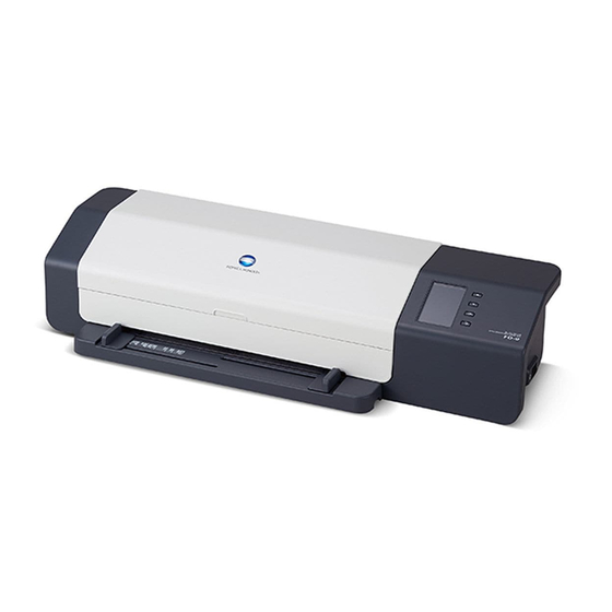
- Page 1 AUTO SCAN SPECTROPHOTOMETER FD-9 E INSTRUCTION MANUAL Before using this instrument, please read this manual.
-
Page 2: Safety Symbols
Safety Symbols The following symbols are used in this manual and on the FD-9 to prevent accidents which may occur as a result of incorrect use of the instrument. Denotes an instruction regarding a safety warning or note. Read the instruction carefully to ensure safe and correct use. -
Page 3: Safety Precautions
AC adapter plug from the AC outlet, and contact the fire or electric shock. nearest Konica Minolta-authorized service facility. If the instrument will not be used for a long time, The instrument should not be operated if it is damaged disconnect the AC adapter plug from the AC outlet. -
Page 4: Introduction
Operating Environment ❙ ❙ • Use the FD-9 at an ambient temperature of between 10°C and 35°C and relative humidity of 30 to 85% with no condensation. Do not use the instrument in areas subject to rapid temperature changes. • Do not leave the FD-9 in direct sunlight or near sources of heat, such as stoves, etc. The internal temperature of the instrument may become much higher than the ambient temperature in such cases. -
Page 5: Notes On Cleaning
• If the internal White Calibration Plate becomes dirty, it can be cleaned according to the procedure on p. 30. • If the FD-9 breaks down, do not try to disassemble and repair it by yourself. Contact a KONICA MINOLTA authorized service facility. -
Page 6: Table Of Contents
Connecting FD-9 to Computer using USB cable ................................. 18 Determining connected USB port number..................................19 Setting Network Settings for Connecting FD-9 to Computer via a LAN ..........................20 Setting network settings directly ....................................20 Setting network settings via DHCP ....................................22... - Page 7 Troubleshooting ����������������������������������������������������������������������������������������������������������������������������������������������������������������������� 27 Error messages ............................................. 27 Clearing paper jams ..........................................27 When using FD-9 without Auto Sheet Feeder ................................27 When using FD-9 with Auto Sheet Feeder ................................... 28 Cleaning ����������������������������������������������������������������������������������������������������������������������������������������������������������������������������������� 30 Cleaning the white calibration plate ....................................30 Cleaning inside the FD-9 ........................................
-
Page 8: Unpacking
The tapes must be removed before use. After unpacking the FD-9 and placing it in its final location, remove the tape strips ① and ② as indicated in the illustrations below. Open the cover and remove tape ③ as shown at right. If power is switched on before tape ③... -
Page 9: Standard Accessories
Standard Accessories AC Adapter AC-A324F Used to supply power from an AC outlet to the instrument. Input: 100 to 240 V 50/60Hz Output (Typical): 24 V 6.25A (STD-24050) USB Cable (3m) IF-A18 Used to connect the instrument to a computer. Paper Guide Used to guide the test chart into the instrument when feeding test charts manually. -
Page 10: Optional Accessories
Optional Accessories Auto Sheet Feeder FD-A09 Used to automatically feed test charts into the instrument. Capacity: 100 sheets... -
Page 11: System Diagram
System Diagram... -
Page 12: Names And Functions Of Parts
Names and Functions of Parts Cover Paper guide mounting slots For attaching the Paper Guide. Display panel Shows instrument settings, status, error messages, etc. Up / down buttons For selecting items from the setting screen or making numerical settings. button For confirming selection or settings. -
Page 13: Preparations
Preparations... -
Page 14: Setting Up Fd-9
❙ ❙ The FD-9 should be set up on a flat, level surface with sufficient space for the color chart in front of and behind the FD-9. There should be enough space in front of the FD-9 for the color chart to be measured to be inserted into and ejected from the FD-9 without any obstacles, and enough space behind the FD-9 for the color chart to fully extend from the FD-9 without obstacles. -
Page 15: Attaching/Removing Paper Guide
• If the Auto Sheet Feeder FD-A09 will be used, the Paper Guide should be removed. • When the Paper Guide is not attached to the FD-9, it should be stored carefully where it will not be lost or broken. -
Page 16: Attaching/Removing Auto Sheet Feeder Fd-A09 (Optional Accessory)
❙ ❙ The optional Auto Sheet Feeder FD-A09 can automatically feed a stack of test charts into the FD-9. Up to 100 test charts can be placed in the Auto Sheet Feeder, and they will be automatically fed into the FD-9 one by one to be scanned. -
Page 17: Removing
Switch off the power of the FD-9. Unplug all cords and cables (AC adapter power cord, USB cable, LAN cable) from the FD-9. Lift the FD-9 straight up off of the Auto Sheet Feeder. Replace the Auto Sheet Feeder connector cover on the FD-9. -
Page 18: Connecting The Ac Adapter
• Always use the AC adapter supplied as a standard accessory or a specified replacement AC adapter, and use the AC adapter only with an AC outlet of the rated voltage and frequency. Failure to do so may damage the FD-9 or AC adapter, or may cause electric shock or fire. -
Page 19: Switching Power On/Off
Slide the power switch to on ( | ). The FD-9 will start up. The Konica Minolta logo will be displayed for a few seconds, followed by the initialization display. When initialization has been completed (after about 25 seconds), the “Please connect” display will be shown. -
Page 20: Connecting Fd-9 To Computer
Connecting FD-9 to Computer The FD-9 can be connected to the computer directly using a USB cable or via a LAN. When connecting via a LAN, either DHCP or a fixed IP address can be used. Connecting FD-9 to Computer using USB cable ❙... -
Page 21: Determining Connected Usb Port Number
Connecting FD-9 to Computer Determining connected USB port number The number of the USB port assigned to the FD-9 is required when connecting to the FD-9 via USB. To see which port has been assigned, follow the steps below. On Windows 7: Open Control Panel. -
Page 22: Setting Network Settings For Connecting Fd-9 To Computer Via A Lan
Setting Network Settings for Connecting FD-9 to Computer via a LAN ❙ ❙ The FD-9 can be connected to a LAN and shared by multiple computers. When connecting the FD-9 to a LAN, network settings can be performed directly or DHCP (Dynamic Host Configuration Protocol) can be used. - Page 23 “Caution: It reboots after saving setting data” will be shown. Press to save the settings and reboot the FD-9. Once these values have been set, connection to the FD-9 from within the same subnet can be performed by specifying the IP address during connection.
-
Page 24: Setting Network Settings Via Dhcp
Connecting FD-9 to Computer Setting network settings via DHCP If your network has DHCP enabled, you can set DHCP on the FD-9 to “ON” and allow your system to automatically allot the IP address, subnet mask, and default gateway. Changing the DHCP setting Press to open the settings screen. -
Page 25: Taking Measurements
• The supply tray can hold up to 100 sheets of paper. Feeding of the test charts from the supply tray into the FD-9 is controlled by the software. For details, please refer to the software instruction manual. -
Page 26: Settings Screen
The MAC address of the FD-9’s network interface board. Not changeable. Network name The network name assigned to the FD-9. It can be set or changed from within the software. For details, refer to the software instruction manual. Display language English (See p. -
Page 27: Selecting And Changing Settings
Settings screen Selecting and changing settings ❙ ❙ Press to move the cursor to the desired item. The value or current setting of the selected item will appear in the value/setting area. To change the selected item, refer to the page specified for that item in the table above. •... -
Page 28: Setting Display Language
Setting display language The language shown on the display panel can be selected according to the following procedure. Press to open the settings screen. Press repeatedly to select “Display language” and press . A list of the language selections will appear, with the current setting highlighted. -
Page 29: Troubleshooting
If the paper becomes jammed during measurement, follow the procedures below to remove the jammed paper. When using FD-9 without Auto Sheet Feeder When using the FD-9 without the Auto Sheet Feeder, the location of paper jams is usually where the paper is fed between the base and the scan mechanism. -
Page 30: When Using Fd-9 With Auto Sheet Feeder
When using the FD-9 with the Auto Sheet Feeder, the location of paper jams is usually in one of the following locations: Where the paper feeds from the supply tray into the Auto Sheet Feeder and then into the FD-9, within the FD-9, or where the paper feeds from the FD-9 through the Auto Sheet Feeder into the exit tray. - Page 31 Close the top cover and inner cover, and then swing the supply tray mechanism closed again. If there is paper jammed on the exit tray side, remove it. Replace the FD-9 in the Auto Sheet Feeder, connect all cables again, and switch the FD-9 back on.
-
Page 32: Cleaning
❙ ❙ If paper dust, etc. accumulates inside the FD-9, it may cause paper jams or problems with patch recognition. If paper jams or patch recognition problems start to occur more frequently, the inside of the FD-9 should be cleaned according to the procedure below. - Page 33 Wipe off the rubber rollers with alcohol to clean and condition them. Grasp the ends of the FD-9 and tilt the FD-9 body onto the base again. Open the cover Tighten the two screws as shown until snug.
-
Page 34: Scan Measurement Chart Conditions
Scan Measurement Chart Conditions The FD-9 can scan charts conforming to the following conditions: Paper width 45 to 330 mm Paper length 170 to 660 mm Paper thickness 0.05 to 0.45 mm Minimum patch size: 6 x 6 mm Maximum number of patches per page... -
Page 35: Specifications
Measurement range Reflectance: 0 to 150% Short-term repeatability Colorimetric: Within σΔE00 0.05 (Under Konica Minolta test conditions where a white calibration plate is measured 30 times at 10-second intervals after white calibration has been performed.) Inter-instrument agreement Within ΔE00 0.3 (Average of 12 BCRA Series II color tiles compared to values measured with a master body under Konica Minolta standard conditions.) - Page 36 9222-A8AN-11 ©2015 KONICA MINOLTA, INC. BFMBGA Printed in Japan...