
Related Manuals for Honeywell C300


Summary of Contents for Honeywell C300
- Page 1 Honeywell Process Solutions Series 8 C300 Controller User's Guide EXDOC-XX11-en-500A R500 April 2017 Release 500 Honeywell...
- Page 2 In no event is Honeywell liable to anyone for any indirect, special or consequential damages. The information and specifications in this document are subject to change without notice.
- Page 3 About This Document Provides information that assists you in planning and designing activities, as well as the installation, operation, and troubleshooting of C300 Process Controllers in Experion LX system. Intended audience This document is intended for the following users: ...
- Page 4 HART, AI-HL, AI-LLMUX, AO, AO-HART, DI-24, DI-SOE, DO-24B. Fault Tolerant Ethernet Overview and Provides basic installation instructions Implementation Guide and configuration requirements for a Fault Tolerant Ethernet (FTE) network and its components. Series 8 C300 Controller User's Guide R500 Honeywell April 2017...
- Page 5 Honeywell Global TAC – China Contact: +86- 21-2219-6888 Phone: 800-820-0237 400-820-0386 Mail: Honeywell (China) Co., Ltd 33/F, Tower A, City Center, 100 Zunyi Rd. Shanghai 200051, People’s Republic of China Email: Global-TAC-China@honeywell.com R500 Series 8 C300 Controller User's Guide April 2017 Honeywell...
- Page 6 WARNING symbol on the equipment refers the user to the product manual for additional information. The symbol appears next to required information in the manual. Series 8 C300 Controller User's Guide R500 Honeywell April 2017...
- Page 7 Chassis Ground: Identifies a connection to the chassis or frame of the equipment shall be bonded to Protective Earth at the source of supply in accordance with national and local electrical code requirements. R500 Series 8 C300 Controller User's Guide April 2017 Honeywell...
-
Page 9: Table Of Contents
C300 Secondary Controller Installation ..................37 Series 8 I/O modules installation ............41 Series 8 FIM Installation ................41 Upgrading C300 Controller Firmware ............. 41 C300 Controller behavior during firmware upgrade and timeout ..........41 R500 Series 8 C300 Controller User's Guide April 2017... - Page 10 Create C300 Controller and CEE function blocks ....... 46 Configure CEEC300 block ................53 Configure a Secondary C300 Controller block ........58 Convert a non-redundant C300 Controller to a redundant controller ..60 Convert a redundant C300 Controller to a non-redundant controller ..63 Configure IOLINK function blocks ............64 Import/export C300 Controller configuration ........
- Page 11 Server Displays tab ......................157 Control Confirmation tab ......................157 Identification tab ........................157 LOAD C300 CONTROLLER CONFIGURATION ....159 About load operations ................ 159 Loaded versus project database versions ................159 Load initiation and load dialog box ..................160 Load action with compare parameters function ..............
- Page 12 Upload to the Monitoring database ............ 172 7. C300 CONTROLLER OPERATION ........... 173 C300 Controller start up ..............174 C300 Controller states in boot mode ...................176 C300 Controller states in application mode .................177 C300 faceplate indicators/displays ............179 Power and Status LEDs ......................180 Faceplate display information ....................181...
- Page 13 7.12 Viewing controller operation and status in Control Builder ....199 7.13 C300 operating behaviors ..............201 Time management in the C300 Controller ................201 Hardware Watchdog Timer ..................... 202 Critical Task Monitor ........................ 202 7.14 C300 Controller processing overload behavior ......203 Causes of controller overloading .....................
- Page 14 Redundancy Link Status - RDNLINKFAILED ................223 Controller redundancy specifications ..........223 9. C300 CONTROLLER MAINTENANCE ........225 Periodic Checks ..................225 Recommended Spare Parts ..............225 C300 Controller module and IOTA replacement ....... 226 10. C300 CONTROLLER TROUBLESHOOTING ......231 10.1 Overview....................231 10.2 What to do when faults occur ............
- Page 15 Non-redundant C300 Controller with no Memory Retention ..........257 Non-redundant C300 Controller with Memory Retention............258 Redundant Primary C300 Controller with no Memory Retention ........... 261 Redundant Primary C300 Controller with Memory Retention ..........262 Secondary C300 Controller with no Memory Retention ............264 Secondary C300 Controller with Memory Retention ..............
- Page 16 Table 2 C300 Controller IOTA Board Connector Summary ..........33 Table 3 Initial Load Order Guidelines ................162 Table 4 C300 Controller Startup and Power On Self Test routine ....... 174 Table 5 Controller in Boot mode ................... 177 Table 6 C300 Controller in Application mode .............. 177 Table 7 C300 Controller LED indications ..............
- Page 17 Contents Figures Figure 1 Series C form factor example ................25 Figure 2 Redundant C300 Controller block in the Project tree ........27 Figure 3 C300 Controller IOTA Board Features ............33 Figure 4 Sample Load Dialog ..................161 Figure 5 C300 Controller Startup and Boot Mode indications ........176 Figure 6 C300 Controller faceplate features ...............
-
Page 19: C300 Controller Purpose
1. C300 Controller Purpose This chapter provides the tasks that are related to using the C300 Controller with the Experion LX system. The following table provides the sections covered in this chapter. Click the topic to view Topic Getting started task list... -
Page 20: Getting Started
Getting started The following table lists some of the tasks covered in this document that are related to implementing a C300 Controller in your Experion LX R500 system. What task do you want to perform? If You Want to . . . - Page 21 1. C300 Controller Purpose 1.1. Getting started If You Want to . . . Then, see this Topic . . . Review C300 Controller start up routines C300 Controller start up Review C300 Controller operating indications C300 Faceplate indicators/displays Shutdown a C300 Controller...
- Page 22 1. C300 Controller Purpose 1.1. Getting started Series 8 C300 Controller User's Guide R500 Honeywell April 2017...
-
Page 23: C300 Controller Planning And Design
2. C300 Controller Planning and Design This chapter provides information about system planning and design of the C300 Controller. The following table provides the sections covered in this chapter. Click the topic to view it. Topic Review Experion LX system capabilities... -
Page 24: Control Hardware Planning Guide
DI-SOE that supports sequence of events. Series 8 form factor All Series 8 control hardware is constructed using the same form factor; that is, the C300 Controller modules, and Series 8 I/O modules, and Series 8 FIMs all mount on their associated Input Output Termination Assemblies (IOTAs), which are installed on channel hardware specifically designed to support Series 8 hardware installation. - Page 25 2. C300 Controller Planning and Design 2.4. C300 Controller Figure 1 Series 8 form factor example R500 Series 8 C300 Controller User's Guide April 2017 Honeywell...
-
Page 26: C300 Controller
500 milliseconds. C300 Controller block When a C300 Controller block is added to the Project tree in Control Builder, a graphic representation of a controller module and its resident function blocks appears as shown in Figure 2. -
Page 27: C300 Controller Execution Environments
The C300 Controller supports three Execution Environment (EE) function blocks. One is the Control EE block, (CEEC300). The other two are I/O Link blocks, (IOLINK). The IOLINK blocks in the C300 support connection and communication with all Series 8 I/O modules. -
Page 28: I/O Modules Supported By The C300 Controller
The C300 Controller supports Series 8 I/O modules. Series 8 I/O modules are connected to the C300 by a pair of I/O Link Interfaces. Two IO Link interfaces, which are redundant, provide connection between the C300 controller and associated I/O modules. -
Page 29: Control Network Considerations
Control network considerations In Experion LX system, the C300 Controller exists as a single node on a FTE network. FTE is the only supported communication protocol for C300 Controllers with Experion LX. C300 Peer communication with Experion LX nodes The C300 supports peer communications with the C300 Controller nodes in Experion LX Release 500. -
Page 31: C300 Controller Installation And Upgrades
3. C300 Controller Installation and Upgrades This chapter describes the information about installing various Series 8 components. Physical descriptions of the components as well as procedures for installing these components are provided. The following table provides the sections covered in this chapter. Click the topic to view... -
Page 32: Series 8 Control Hardware Installation Requirements
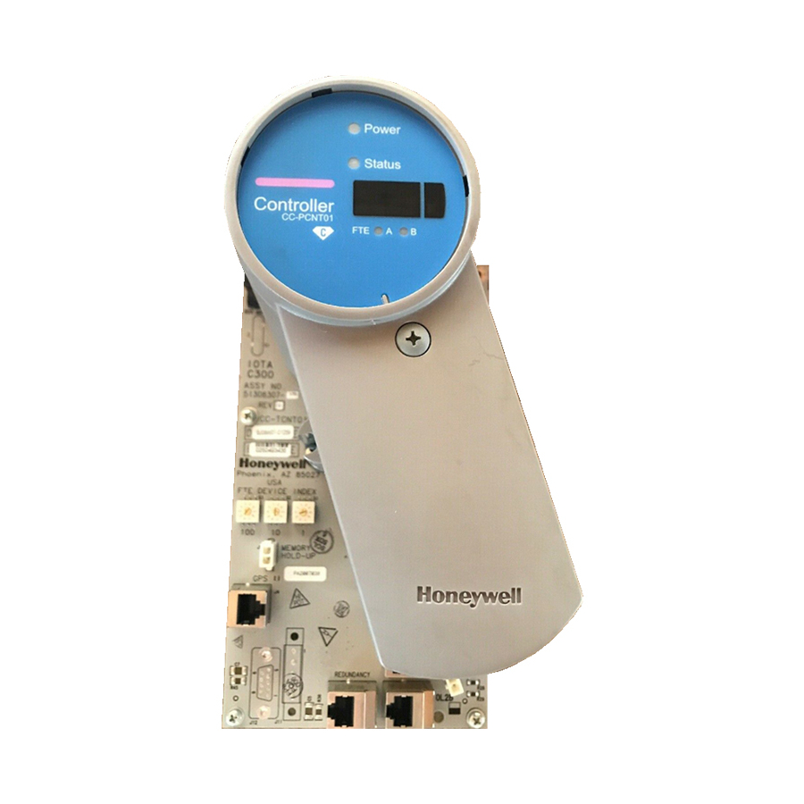
C300 Controller installation C300 Controller assembly The C300 Controller consists of an Input/Output Terminal Assembly (IOTA) board and the controller module which is housed within a plastic cover and is mounted on the IOTA board. The Controller assembly is installed in a control cabinet on vertically-mounted channels specifically for Series 8 control hardware. - Page 33 3. C300 Controller Installation and Upgrades 3.2. C300 Controller installation R500 Series 8 C300 Controller User's Guide April 2017 Honeywell...
-
Page 35: Table 2 C300 Controller Iota Board Connector Summary
3. C300 Controller Installation and Upgrades 3.2. C300 Controller installation Figure 3 C300 Controller IOTA Board Features Table 2 C300 Controller IOTA Board Connector Summary C300 IOTA Board Description Fuse IOL1A, IOL1B (Gray cable) Redundant IOLINK connectors for IOLINK 1 and... - Page 36 A Series 8 power supply and optional battery backup hardware installed in the cabinet. Following are the parts included: C300 Controller assembly (control module with IOTA board and mounting hardware) 2 STP Cat5 Ethernet cables (one Yellow cable, one Green cable) ...
- Page 37 The secondary controller may be installed on a separate channel from the primary controller. To install a C300 Controller, perform the following steps. Step Action Refer to appropriate site location drawings for the specified controller installation location, controller Device Index (FTE address) and wiring diagrams.
- Page 38 Connect a second IOLINK cable pair to IOL2A and IOL2B for IOLINK 2 interface of the controller. Note that when connecting Redundant C300 Controller pairs; connect the primary controller IOLINK and the redundant partner IOLINK to the same IOLink cable pair.
-
Page 39: C300 Secondary Controller Installation
'Module is Redundant' check box. C300 Secondary Controller Installation Creating a C300 Controller redundant pair is as simple as installing a second controller in the control hardware cabinet. Refer to the C300 Controller assembly to review the location of the cable connections. - Page 40 To install a partner secondary C300 Controller, perform the following steps. Step Action If the primary C300 FB already exists in Control Builder and it is currently configured as a redundant controller, select the Redundancy tab and click the Disable Synchronization button to set the Auto-Synchronization State parameter to "DISABLED."...
- Page 41 3. C300 Controller Installation and Upgrades 3.2. C300 Controller installation Step Action Be sure component side of IOTA is facing up. Refer to the figure below. Assemble mounting screws, washers and spacers provided. Insert spacers and washers between backside of IOTA and front of channel.
- Page 42 Connect a second IOLINK cable pair to IOL2A and IOL2B for IOLINK 2 interface of the controller. Note that when connecting Redundant C300 Controller pairs, connect the primary controller IOLINK and the redundant partner IOLINK to the same IOLink cable pair.
-
Page 43: Series 8 I/O Modules Installation
I/O Modules Firmware Upgrade Guide about using CTool to upgrade firmware in Series 8 components C300 Controller behavior during firmware upgrade and timeout The following indications are shown on the faceplate display of the C300 Controller during the firmware upgrade operation. ... - Page 44 3. C300 Controller Installation and Upgrades 3.5. Upgrading C300 Controller Firmware The controller is set to timeout in 4.5 minutes if the firmware upgrade operation is not completed. When the timeout occurs, the controller aborts the upgrade operation and returns to the operating state (ALIV or RDY) prior to the start of the firmware upgrade.
- Page 46 3. C300 Controller Installation and Upgrades 3.5. Upgrading C300 Controller Firmware Series 8 C300 Controller User's Guide R500 Honeywell April 2017...
-
Page 47: C300 Controller Configuration
Create C300 Controller and CEE function blocks Configure CEEC300 block Configure a Secondary C300 Controller block Convert a non-redundant C300 Controller to a redundant controller Convert a redundant C300 Controller to a non-redundant controller Configure IOLINK function blocks Import/export C300 Controller configuration... -
Page 48: Configuration Overview
If you are using Simplified Enterprise Model Builder (SEMB) application to create an asset model of your system, assets that represent C300 Controllers can be created and added to your model following the same procedures for creating assets and alarm groups. -
Page 49: Specifying A Time Server
4.2. Create C300 Controller and CEE function blocks Specifying a Time Server The C300 Controller requires a reference source for time in order to power up and normally operate, but limited controller operation can be achieved in cases where system time is not available. -
Page 50: Create C300 Controller And Cee Function Blocks
Control Execution Environment (CEE). Once created, the function blocks appear in the Project tab view of Control Builder. The CEEC300 block supports execution of a set of function blocks for solving control applications which run in the C300 as a software layer built on top of the control software infrastructure. - Page 51 4. C300 Controller Configuration 4.2. Create C300 Controller and CEE function blocks Considerations All illustrations used in the procedure are for example purposes only. To configure a C300 Controller block, perform the following steps. Step Action Result Click File > New > Controllers > C300 The C300 Block configuration form with a Controller (2 I/O Links).
- Page 52 4. C300 Controller Configuration 4.2. Create C300 Controller and CEE function blocks Step Action Result Enter the desired name of up to 16 Moves cursor to the Item Name field. characters or accept the default. Press <Tab>. Note: Tag Name is limited to 16...
- Page 53 4. C300 Controller Configuration 4.2. Create C300 Controller and CEE function blocks Step Action Result In the Temperature High Alarm (degC) Moves cursor to the CPU Free Low field, accept the default or enter a value Alarm (%) field. at which an alarm is generated for controller hardware high temperature.
- Page 54 4. C300 Controller Configuration 4.2. Create C300 Controller and CEE function blocks Step Action Result If you have a Distributed Server Architecture (DSA), you must enter the Control Area assignment for this Server. (Note that area code assignments are made through the Station application.) If you do not have a DSA, you can skip this field if area is not...
- Page 55 4. C300 Controller Configuration 4.2. Create C300 Controller and CEE function blocks Step Action Result Use the on-line help as a guide to The Server Displays configuration form complete the configuration entries on this appears. tab. Click the Server Displays tab.
- Page 56 4. C300 Controller Configuration 4.2. Create C300 Controller and CEE function blocks Step Action Result The following block icons now appear in the Project window: C300 Controller block, and its associated CEEC300 block 2 IOLINK blocks and ...
-
Page 57: Configure Ceec300 Block
4. C300 Controller Configuration 4.3. Configure CEEC300 block Configure CEEC300 block A CEE block is created automatically when a C300 Controller function block is added to the Project tab. Prerequisites Control Builder is running Tree windows are open Considerations All illustrations used in the procedure are for example purposes only. - Page 58 Enter the desired name of up to 16 Moves cursor to Item Name field. characters or accept the default. Press <Tab>. Enter Item Name. Press <Tab>. Moves cursor to Base Execution Period field. Series 8 C300 Controller User's Guide R500 Honeywell April 2017...
- Page 59 Otherwise, an error message appears as follows: "CEE BASEPERIOD cannot be changed because IOLINK TYPE of at least one IOLINK of this C300 has been configured.” Accept the default or select desired Moves cursor to User Lock for CEE Idle field.
- Page 60 Click Server History tab and proceed to Step 25. Enter the valid name for the existing Moves cursor to Peer Subscription Period peer environment. column. Press <Tab>. Series 8 C300 Controller User's Guide R500 Honeywell April 2017...
- Page 61 Click OK. REFERENCE - INTERNAL Refer to the Experion LX Control Builder Components Reference, Component Categories and Types and the Experion LX Planning Guide. R500 Series 8 C300 Controller User's Guide April 2017 Honeywell...
-
Page 62: Configure A Secondary C300 Controller Block
4. C300 Controller Configuration 4.4. Configure a Secondary C300 Controller block Configure a Secondary C300 Controller block When a C300 Controller is configured as Redundant, the Secondary C300 Controller block is added to the Project tab automatically. Prerequisites Control Builder is running ... - Page 63 4. C300 Controller Configuration 4.4. Configure a Secondary C300 Controller block Step Action Result Enter the desired name of up to 16 Moves cursor to the Item Name field. characters or accept the default. Press <Tab>. Enter Item Name. Press <Tab>.
-
Page 64: Convert A Non-Redundant C300 Controller To A Redundant Controller
Tree windows are open Ensure that a C300 Controller is properly installed in the same control cabinet as the C300 Controller designated to become the redundant partner. The C300 Controller hardware and firmware must be identical for both controllers in a redundant pair. - Page 65 4. C300 Controller Configuration 4.5. Convert a non-redundant C300 Controller to a redundant controller Step Action Result icon. Click Module Properties... The C300 Block configuration form. Select the Module is redundant A default tag name of the secondary check box.
- Page 66 4. C300 Controller Configuration 4.6. Convert a redundant C300 Controller to a non-redundant controller Step Action Result Click OK. The C300 Controller configuration form closes. In the Project window: The C300 Controller icon indicates that it is configured as redundant, (showing a double controller icon).
-
Page 67: Convert A Redundant C300 Controller To A Non-Redundant Controller
Control Builder is running Tree windows are open Make sure that the current primary C300 Controller is physically configured with the odd Device Index. If not, enable synchronization, wait for initial-sync to complete, and manually command switchover. Considerations This procedure can be performed on-process. -
Page 68: Configure Iolink Function Blocks
Configure IOLINK function blocks Two IOLINK blocks are created automatically when a C300 Controller function block is added to the Project tab. These blocks provide the interface to the controller for associated I/O Module blocks. - Page 69 4.7. Configure IOLINK function blocks Step Action Result In the Project window, right-click on the The shortcut menu appears. IOLINK_1BLK block icon. Click Module Properties... The IOLINK Block configuration form appears. R500 Series 8 C300 Controller User's Guide April 2017 Honeywell...
- Page 70 Accept the default or click the drop-down The IOLINK block configuration form list and select the I/O type. closes since no other data on this form is available in the Project mode. Click OK. Series 8 C300 Controller User's Guide R500 Honeywell April 2017...
-
Page 71: Import/Export C300 Controller Configuration
When using the export function the Device Index information for the C300 is exported, but not the controller's IP Address. This enables import of the C300's configuration into a different server cluster, and allows the C300 to use a different IP Address based upon that server cluster's base IP Address. - Page 72 IP Address based on this new Device Index. In the Control Builder, configure as a new controller. Refer to the C300 Controller Configuration to configure a new controller. Series 8 C300 Controller User's Guide R500 Honeywell April 2017...
-
Page 73: 4.10 Create A Control Module
The following graphic shows Control Builder with a Control Module chart shown in the control drawing area. Prerequisites Control Builder is running Tree windows are open R500 Series 8 C300 Controller User's Guide April 2017 Honeywell... - Page 74 The new Control Module is automatically saved to your hard drive. Select Edit > Module Properties… or double-click inside the chart to open the Control Module parameter configuration form for input. Series 8 C300 Controller User's Guide R500 Honeywell April 2017...
- Page 75 Enter a new Control Module name in the Name field along with a description in the Description field. Using the F1 key to access context-sensitive Help, fill in the remaining fields as required. R500 Series 8 C300 Controller User's Guide April 2017 Honeywell...
-
Page 76: Assign Control Modules And Ioms To A Ceec300 Block
Once a Control Module (CM) or Sequential Control Module (SCM) is created, you can assign it to a CEEC300 block of a C300 Controller. Use the following procedure as a general guide to assign configured CMs and I/O Modules (IOMs) to the CEEC300 block. - Page 77 (There is no set of Assignment. Or, click assignment default state for the dialog, so it may button in the toolbar. appear with different active fields than shown below.) R500 Series 8 C300 Controller User's Guide April 2017 Honeywell...
- Page 78 Available Modules and Assigned Modules lists. With CMs/SCMs tab selected, click listed Highlights selection and configured CM to be assigned to a CEE. CEEs appear in the Assign To list. Series 8 C300 Controller User's Guide R500 Honeywell April 2017...
- Page 79 Be sure correct CEE is selected in list. desired CEE in list. Selected CM is assigned to the selected Click the CEE and appears in the Assigned assign button. Modules list. R500 Series 8 C300 Controller User's Guide April 2017 Honeywell...
- Page 80 4. C300 Controller Configuration 4.11. Assign Control Modules and IOMs to a CEEC300 block Step Action Result Click IOMs tab in Available Modules Configured IOMs appear in list. section. Series 8 C300 Controller User's Guide R500 Honeywell April 2017...
- Page 81 CEE and appears in the Assigned assign button. Modules list. Repeat Steps 2 to 4 to assign other Complete CM, SCM, and IOM CMs/SCMs. Or, repeat Steps 5 to 8 to assignments. assign other IOMs. R500 Series 8 C300 Controller User's Guide April 2017 Honeywell...
-
Page 82: 4.12 Copy Control Modules
Project Tree. copied. Click Edit > Copy. Selected Control Module block is saved to Control Builder clipboard Alternate method: and Name New Function Block(s)… dialog appears. Click <Ctrl>-C. Series 8 C300 Controller User's Guide R500 Honeywell April 2017... - Page 83 4. C300 Controller Configuration 4.13. Assign I/O Modules to C300 IOLINK blocks Step Action Result Change the Control Module block's The copied Control Module block is Tagname in the Destination column of assigned a new name. the Name New Function Block(s) dialog...
-
Page 84: 4.13 Assign I/O Modules To C300 Iolink Blocks
IOLINK blocks. ATTENTION I/O assigned to the I/O Link of a C300 may only be associated with and directly controlled by the CEE executing on the same C300 Controller. In other words, I/O devices operating on a C300 Controller's I/O Link may not be directly associated with control strategies running on the CEE of another controller. - Page 85 4. C300 Controller Configuration 4.13. Assign I/O Modules to C300 IOLINK blocks To assign Series 8 IO Modules to IOLINK blocks, perform the following steps. Step Action Result Click Edit > Execution Environment The Execution Environment Assignment dialog box appears. (There is no set Assignment.
- Page 86 4. C300 Controller Configuration 4.13. Assign I/O Modules to C300 IOLINK blocks With IOMs tab selected, click desired Highlights selection and configured IOM to be assigned to given IOLINK. IOLINKs appear in the Assign To list. Accept default IOLINK selection or click Be sure correct IOLINK is selected in list.
- Page 87 4. C300 Controller Configuration 4.13. Assign I/O Modules to C300 IOLINK blocks Repeat Steps 2 to 4 to assign other Complete IOM assignments. IOMs. R500 Series 8 C300 Controller User's Guide April 2017 Honeywell...
-
Page 88: 4.14 Add An I/O Channel To A Control Module
Control Builder is running Tree windows are open Considerations All illustrations used in the procedure are for example purposes only. Blocks appear as Block Symbols on the Control Module chart. Series 8 C300 Controller User's Guide R500 Honeywell April 2017... - Page 89 Control Building Guide. If you are building a control strategy to include insertion points, refer to Creating a strategy to use insertion points in the Control Building User’s Guide. R500 Series 8 C300 Controller User's Guide April 2017 Honeywell...
-
Page 91: C300 Configuration Form Reference
Controller block. The Main tab contains most of the parameters that must be configured when setting up a C300 Controller. It also displays the important states of the C300 Controller and supports the key commands associated with C300 Controller operation. - Page 92 Embedded FTE Base Ethernet IP Address and the configured Device Index. State Information Controller State C300STATE Shows C300 Controller's current module state. Redundancy Role RDNROLESTATE Shows C300 Controller's current redundancy role. Series 8 C300 Controller User's Guide R500 Honeywell April 2017...
- Page 93 Advanced Configuration ALMENBSTATE Alarming Enabled Allows user to set the alarm reporting function used when an alarm condition is detected by the function block. R500 Series 8 C300 Controller User's Guide April 2017 Honeywell...
- Page 94 Host IP Address HOSTIPPRI Indicates the IP address for the node hosting the simulation program. Host Name HOSTNAMEPRI Specifies the network name for the node hosting the simulation program. Simulation Node Operation Series 8 C300 Controller User's Guide R500 Honeywell April 2017...
-
Page 95: Redundancy Tab
Redundancy tab The Redundancy Tab displays redundancy-related information and allows redundancy commands to be issued when the C300 FB is opened on the Monitor Tree in Control Builder. The following table summarizes the parameter data you can monitor and/or R500... - Page 96 5. C300 Configuration Form Reference 5.1. C300 Controller Block configure on the Redundancy tab of the configuration form for the selected C300 block. Refer to the Redundancy parameters for further descriptions of these parameters. Note that the Redundancy tab is exposed only when the Controller is configured as redundant.
- Page 97 RDNXFERMAX Max Redundancy Maximum amount of redundancy data traffic Traffic (bytes/sec) across the redundancy private path throughput since power up or last statistics reset. R500 Series 8 C300 Controller User's Guide April 2017 Honeywell...
- Page 98 RDNOPMSTATUS OPM Status Status parameter indicating the notifications Note: This parameter generated by the primary is not supported in controller during an On- this release. Process Migration session. Series 8 C300 Controller User's Guide R500 Honeywell April 2017...
-
Page 99: System Time Tab
5.1. C300 Controller Block System Time tab The System Time tab contains information about the C300 Controller's time source and synchronization with that time source. The "System Time" and "System Time Synchronization Status" subgroups on this tab provide current controller system time and indicates the time source with which it is synchronized and status of synchronization with that source. -
Page 100: Statistics Tab
Statistics tab The Statistics Tab contains various statistical parameters used for maintaining and monitoring C300 Controller performance. Such information includes CPU utilization, hardware temperature and communications sub-system (CDA) statistics. The following table summarizes the parameter data you can monitor on the Statistics tab of the configuration form for the selected C300 block. - Page 101 Initiator Output Rate TINUMOUTMSGAVGP Max Initiator Output TINUMOUTMSGMAXP Rate Responder Input TRNUMINMSGAVGPS Rate TRNUMINMSGMAXPS Max Responder Input Rate Responder Output TRNUMOUTMSGAVGP Rate Max Responder TRNUMOUTMSGMAXP Output Rate PCDI Network Message Statistics R500 Series 8 C300 Controller User's Guide April 2017 Honeywell...
-
Page 102: Peer Connections Tab
Peer Connections tab The Peer Connections tab contains data indicating the number of peer connections for both initiator and responder types between the C300 Controller and other peer-capable nodes, such as, C300 Controllers. The following table summarizes the parameter data you can monitor on the Peer Connections tab of the configuration form for the selected C300 block. - Page 103 5.1. C300 Controller Block Peer Responding Connections Responding to C300s TNUMC3OUTCON Shows the number of originator C300 Controllers. Responding to FIM4s TNUMSCFIMOUTCON Shows the number of originator Series 8 FIMs. R500 Series 8 C300 Controller User's Guide April 2017 Honeywell...
-
Page 104: Hardware Information Tab
The parameters provided here are used for maintenance, troubleshooting and problem description purposes. The following table summarizes the parameter data you can view on the Hardware Information tab of the configuration form for the selected C300 block. Plain Text... -
Page 105: Fte Tab
Two separate MARTs are maintained - one for FTE nodes and one for non-FTE nodes. The following table summarizes the parameter data you can monitor on the FTE tab of the configuration form for the selected C300 block. Plain Text Parameter Name... - Page 106 LANARXRATE Indicates communication receive rate in kilobits per (kBit/sec) second (kbps) for port A Note: This parameter (Yellow Tree Port) on the is not supported in FTE Bridge. this release. Series 8 C300 Controller User's Guide R500 Honeywell April 2017...
- Page 108 (kbps) for port B (Green is not supported in Tree Port) on the FTE this release. Bridge. FTE Statistics Number of FTE NUMFTENODES Current number of FTE Nodes nodes within FTE community. Series 8 C300 Controller User's Guide R500 Honeywell April 2017...
- Page 109 Port B. InterLAN Comm INTERLANFAILED Status indicator for Inter- Failed LAN communications - indicates that inter-LAN communications have failed. R500 Series 8 C300 Controller User's Guide April 2017 Honeywell...
-
Page 110: Utp/Tcp Tab
UTP/TCP tab The UDP/TCP tab displays statistics related to open UDP and TCP connections associated with this C300 Controller. These parameters provided here are used for maintenance and performance monitoring purposes. The following table summarizes the parameter data you can monitor on the UDP/TCP tab of the configuration form for the selected C300 block. - Page 111 LISTEN state from SYN-RCVD state. Connection Resets TCPESTABRESETS Number of times TCP connections have made a direct transition to CLOSED state from either ESTABLISHED state or CLOSE-WAIT state. R500 Series 8 C300 Controller User's Guide April 2017 Honeywell...
-
Page 112: Ip/Icmp Tab
The IP/ICMP tab displays statistics related to IP and ICMP protocol messages associated with (that is, originating in or received by) this C300 Controller. These types of messages are generally associated with maintenance and status operations on the network. The following table summarizes the parameter data you can monitor on the IP/ICMP tab of the configuration form for the selected C300 block. - Page 113 Number of input IP Discarded for Resrcs datagrams for which no problems were encountered to prevent their continued processing, but which were discarded; for example, for lack of buffer space. R500 Series 8 C300 Controller User's Guide April 2017 Honeywell...
- Page 114 IPREASSEMOKS Number of IP datagrams Reassembled successfully reassembled. Fragments IPREASSMFAILS Number of failures Reassembly Fails detected by the IP reassembly algorithm, for whatever reason: timed out, errors, and so on. Series 8 C300 Controller User's Guide R500 Honeywell April 2017...
- Page 115 ICMP-specific errors such as bad ICMP checksums and bad length. Dest. Unreachable ICMPINDESTUNREAC Number of ICMP Msgs Recvd Destination Unreachable messages received. R500 Series 8 C300 Controller User's Guide April 2017 Honeywell...
-
Page 116: Soft Failures Tab
Number of ICMP Echo Messages Sent Reply messages sent. Soft Failures tab The Soft Failures tab provides indications of various soft failure conditions for the C300 Controller hardware. Refer to the C300 Controller soft failures table in the Troubleshooting section for more detailed information and corrective actions in clearing these faults. - Page 117 Warning Watchdog Timer is being refreshed late and close to the timeout limit. Critical Task TASKHLTHMON A key task within the Watchdog Warning controller is executing less frequently than normal. R500 Series 8 C300 Controller User's Guide April 2017 Honeywell...
-
Page 118: Server History Tab
The Server History tab is common to all configuration forms for tagged blocks in Control Builder. The following table summarizes the parameter data you can monitor and configure on this tab of the configuration form for the selected C300 block. ATTENTION... - Page 119 Select the Exception type of (Station history collection. only) Gating Parameter HIST.GATEPARAM Optional gating parameter to define conditions under which data for this parameter should be collected. Gate State HIST.GATEVALUE Defines gate state for R500 Series 8 C300 Controller User's Guide April 2017 Honeywell...
-
Page 120: Server Displays Tab
The Server Displays tab is common to all configuration forms for tagged blocks in Control Builder. The following table summarizes the parameter data you can monitor and configure on this tab of the configuration form for the selected C300 block. ATTENTION... - Page 121 Number of Groups GROUP.NUMPARAMS Defines the number of group parameters to be included in Groups Configuration table. Group # GROUP.NUMBER Defines Group number to be associated with this group parameter. R500 Series 8 C300 Controller User's Guide April 2017 Honeywell...
-
Page 122: Control Confirmation Tab
The Identification tab is common to all configuration forms for tagged blocks in Control Builder. The following table summarizes the parameter data you can monitor and configure on this tab of the configuration form for the selected C300 block. Plain Text... - Page 123 Otherwise, it may just show default login. If this block is in Version Control System, modifications apply to last version of block. R500 Series 8 C300 Controller User's Guide April 2017 Honeywell...
-
Page 124: Secondary C300 Block
(MODISREDUN) check box is selected on the Primary C300 configuration form Main tab. The Secondary C300 configuration form contains the same tabs and parameters as the primary with the exception of a few parameters on the Main and Redundancy tabs. -
Page 125: Ceec300 Function Block
5.3. CEEC300 Function Block CEEC300 Function Block The CEEC300 function block is created when a new C300 Controller block is created and configured in the Project tree in Control Builder. The following sections identify and describe all user-visible parameters associated on the CEEC300 configuration form. For more details about these parameters refer the Control Builder Parameter Reference. - Page 126 Enable Memory Limit Allows user to enable Exceeded Alarm the alarm reporting function for Memory Limit Exceeded alarm. Powerup/Restart Settings RRRCEESTATE CEE State Shows the CEE state after a RAM retention restart. Series 8 C300 Controller User's Guide R500 Honeywell April 2017...
- Page 127 Inhibit Notifications - NOTIFINHIBIT Indicates if the display of CEE and Contents notifications associated with the CEESIMC300 and its contents is inhibited on the Station's Alarm Summary. R500 Series 8 C300 Controller User's Guide April 2017 Honeywell...
-
Page 128: Peer Configuration Tab
Store Expiration Time PEERSTRRESP [ ] Shows the expiration time used in waiting for Store responses for specific CEE peers (such as C300s) and non-CEE data servers (such as OPC Servers). Series 8 C300 Controller User's Guide R500 Honeywell April 2017... -
Page 129: Statistics Tab
Maximum NUMNTFRQUMAX The number of Notifications Rate Notification Requests per second maximum. Whole Array Transfer Statistics CPEERWAAVGPPS Whole Array (WA) Indicates the average Peer Responder peer responder rate. Rate R500 Series 8 C300 Controller User's Guide April 2017 Honeywell... - Page 130 Exchange Statistics Exchange Request NUMEXCRQUAVG The average exchange Rate request throughput. Maximum Exchange NUMEXCRQUMAX The maximum Request Rate exchange request throughput. Exchange Response NUMEXCRSPAVG The average exchange Rate response throughput Series 8 C300 Controller User's Guide R500 Honeywell April 2017...
- Page 131 CEE per second. Maximum OPC EXTGETRQUMAX The maximum number Pull/Get Rate of completed Get requests to all external servers, such as an OPC server, from this CEE per second. R500 Series 8 C300 Controller User's Guide April 2017 Honeywell...
- Page 132 Maximum Transmit NUMMBTCPXMITMSG The maximum number Messages/sec of Modbus TCP transmit messages on average per second. Transmit Bytes/sec NUMMBTCPXMITBYTE The number of Modbus TCP transmit bytes on average per second. Series 8 C300 Controller User's Guide R500 Honeywell April 2017...
- Page 133 Maximum Receive NUMMBTCPRCVBYTE The maximum number Bytes/sec of Modbus TCP receive bytes per second. Invalid Receive MBTCPINVALIDRCVM The Modbus TCP SGCOUNT Message Count invalid receive message count. R500 Series 8 C300 Controller User's Guide April 2017 Honeywell...
-
Page 134: Cpu Loading Tab
For example: CPUCYCLEAVG[0] is for Phase 1; CPUCYCLEAVG[1] is for Phase 2; and so on. CPUCYCLEAVG [40] contains the average value across all 40 phases. Series 8 C300 Controller User's Guide R500 Honeywell April 2017... -
Page 135: Cpu Overruns Tab
CEEC300 block. Plain Text Parameter Name User Notes Configurable CPU Overruns Table (%) Current Hour Cycle CRCYCLEOVRN A count of cycle [0…40] Overruns overruns that have occurred during the current hour. R500 Series 8 C300 Controller User's Guide April 2017 Honeywell... -
Page 136: Memory Tab
Memory tab The Memory tab contains data on general memory usage in the C300. It also shows memory usage parameters in terms of internal memory units: descriptors and blocks. The following table summarizes the parameter data you can monitor on the Memory tab of the configuration form for the selected CEEC300 block. - Page 137 Free Memory Blocks Number of free (available) memory blocks. External Memory NUMEXTBLKS Number of external Blocks memory blocks. Stack Usage MAXSTACK Maximum CEEB Maximum CEE Stack % budgeted stack in percent. R500 Series 8 C300 Controller User's Guide April 2017 Honeywell...
-
Page 138: Peer Communications Tab
IOLINK peer originator block. CPEERAVGPPSCONN Average Get Rate The average number of peer parameters/sec processed by the CEE. CPEERMAXPPSCONN Maximum Get Rate The maximum number of peer parameters/sec processed by the CEE. Series 8 C300 Controller User's Guide R500 Honeywell April 2017... -
Page 139: Exchange Communications Tab
Note: This tab is not supported in this release. The Exchange Communications tab contains information about exchange connections between the C300 controller and a target controller or programmable logic controller. It gives statistics for connections initiated by the CEEC300 block. The following table summarizes the parameter data you can monitor on the Exchange Communications tab of the configuration form for the selected CEEC300 block. -
Page 140: Display Communications Tab
Display Communications tab The Display Communications tab contains information about display connections to the C300 (that is, Control Builder, Station, and so on). The following table summarizes the parameter data you can monitor on the Display Communications tab of the configuration form for the selected CEEC300 block. -
Page 141: Block Types Info Tab
CCL Library BLKTYPLIB Shows the name of the CCL containing the block type. Block Size (bytes) BLKTYPSIZE Shows the size of the block type footprint. R500 Series 8 C300 Controller User's Guide April 2017 Honeywell... -
Page 142: Cab Types Info Tab
CAB load. If you want to disable CAB in a C300 where it was previously enabled, you must first delete all CAB instances and types from the controller. Series 8 C300 Controller User's Guide R500 Honeywell April 2017... -
Page 143: Custom Types Info Tab
Custom Types Info tab of the configuration form for the selected CEEC300 block. Plain Text Parameter Name User Notes Configurable Custom Types Represented Custom Data Blocks(CDB) and Phase Blocks Instantiated Block NUMCDDMTYPES The number of custom data definition manager Types types. R500 Series 8 C300 Controller User's Guide April 2017 Honeywell... -
Page 144: Server History Tab
Builder. Refer to the Identification tab for a table that summarizes the parameter data you can monitor and configure on this tab of the configuration form for the selected CEEC300 block. Series 8 C300 Controller User's Guide R500 Honeywell April 2017... -
Page 145: Iolink Block
5.4. IOLINK Block IOLINK Block The IOLINK function block is created when a new C300 Controller block is added to the Project tree in Control Builder. The following sections identify and describe all user- visible parameters associated on the IOLINK configuration form. For more details about these parameters refer to the Control Builder Parameter Reference. - Page 146 Shows the I/O link has Exceeded exceeded the maximum error limit. Not Active Supervisor NOTACTSUPV Indicates that the IOL interface daughter card could not transition into the active supervisor role. Series 8 C300 Controller User's Guide R500 Honeywell April 2017...
-
Page 147: Memory Stats Tab
Memory Stats tab of the configuration form for the selected IOLINK block. Plain Text Parameter Name User Notes Configurable Memory Stats R500 Series 8 C300 Controller User's Guide April 2017 Honeywell... - Page 148 Memory Buffers In BUFXUSED The current number of memory buffers used in the Monitoring mode. Maximum Memory BUFXMAX The maximum number Buffers Used of memory buffers used. Series 8 C300 Controller User's Guide R500 Honeywell April 2017...
-
Page 149: Statistics Tab
Channel A+ Edges PRIIFCHNPLA The number of I/O link channel A missed and the edge transitions encountered locally by the primary link interface. R500 Series 8 C300 Controller User's Guide April 2017 Honeywell... - Page 150 Last IOL Command LASTIOLCMD The last I/O link command requested through the COMMAND parameter or the last SELECT_CH_A / SELECT_CH_B command automatically issued when periodic channel swap is enabled. Series 8 C300 Controller User's Guide R500 Honeywell April 2017...
- Page 151 The number of I/O Link channel B errors encountered by the Secondary Link Interface. Channel B Silences SECIFCHNSILB The number of I/O Link channel B silences encountered by the Secondary Link Interface. R500 Series 8 C300 Controller User's Guide April 2017 Honeywell...
- Page 152 Channel A+ Total TOTCHNPLA The total I/O Link Edges missed and the edge transitions on channel Channel B Total TOTCHNERRB The total I/O Link errors Errors on channel B. Series 8 C300 Controller User's Guide R500 Honeywell April 2017...
- Page 153 The number of I/O link overruns that have Hour occurred in the current hour. Overruns - Previous OVERRUNSPREV Shows the number of Hour I/O link overruns that have occurred in the previous hour. R500 Series 8 C300 Controller User's Guide April 2017 Honeywell...
- Page 154 Local Data Transfer LCDXFIFORATEA Indicates the average number of parameters accessed through Local Data Transfer FIFO per second. DIFIFORATEA DI Priority DO Priority DOFIFORATEA Maximum I/O Link Requests Per Second Series 8 C300 Controller User's Guide R500 Honeywell April 2017...
- Page 155 OVRRUNCURHR Overruns Current Process Data Cycle Overruns that have Hour occurred during the Current Hour. Overruns Previous OVRRUNPREVHR Process Data Cycle Hour Overruns that have occurred in the Previous Hour. R500 Series 8 C300 Controller User's Guide April 2017 Honeywell...
-
Page 156: I/O Link Status Tab
PRIRCVCHN Indicates the channel that is actively listening to the transmitted messages. Channel A Errors PRICHNERRA Shows the number of I/O link channel A errors encountered by the Primary IOP. Series 8 C300 Controller User's Guide R500 Honeywell April 2017... - Page 157 The number of I/O link channel B missed plus edge transitions encountered by the primary IOM. PRICOMMERR Last Error Shows the last I/O Link communication error experienced by the Primary IOP. Secondary IOPs R500 Series 8 C300 Controller User's Guide April 2017 Honeywell...
- Page 158 Indicates the number of I/O link channel B errors encountered by the Secondary IOP. Channel B Silences SECCHNSILB Shows the number of I/O link channel B silences encountered by the Secondary IOP. Series 8 C300 Controller User's Guide R500 Honeywell April 2017...
-
Page 159: I/O Status Summary Tab
IOP Block Name corresponding Primary IOP/IOM Tag. Configured IOP Type IOMTYPE Indicates the configured IOP type. IOP Status IOMSTSA and Shows the status of the IOMSTSB specific physical I/O Module. R500 Series 8 C300 Controller User's Guide April 2017 Honeywell... - Page 160 Overruns - Previous IOPORPREV Indicates the number of Hour I/O Link overruns that have occurred in the previous hour. Cached Parameters NUMCACHE The number of cached parameters residing in the IOLINK. Series 8 C300 Controller User's Guide R500 Honeywell April 2017...
-
Page 161: Iota Summary Tabs
Active Receive Indicates the actual Channel active receive channel for the Series 8 IOM. Channel A Errors PHYCHNERRASC1 Shows the I/O Link errors on Channel A for the Series 8 IOM. R500 Series 8 C300 Controller User's Guide April 2017 Honeywell... -
Page 162: Server History Tab
Builder. Refer to the Server History tab for a table that summarizes the parameter data you can monitor and configure on this tab of the configuration form for the selected CEEC300 block Series 8 C300 Controller User's Guide R500 Honeywell April 2017... -
Page 163: Server Displays Tab
Builder. Refer to the Identification tab for a table that summarizes the parameter data you can monitor and configure on this tab of the configuration form for the selected CEEC300 block. R500 Series 8 C300 Controller User's Guide April 2017 Honeywell... -
Page 165: Load C300 Controller Configuration
6. Load C300 Controller Configuration This chapter describes the information about tasks associated with loading C300 Controller configuration using Control Builder. The following table provides the sections covered in this chapter. Click the topic to view it. Topic About load operations... -
Page 166: Load Initiation And Load Dialog Box
Either command invokes the Load Dialog dialog box. The following figure shows a sample Load Dialog dialog box invoked for a load with contents operation for a C300. It provides a brief description of the dialog box features for quick reference. The appearance of the dialog box will vary depending on the current load circumstances such as whether this is an initial load or a re-load operation. -
Page 167: Load Action With Compare Parameters Function
You can enable or disable the loading of history, trend, or group configuration data for a block to Server through the System Preferences dialog box. Refer to the Setting system preferences section in the Control Building User’s Guide for more information. R500 Series 8 C300 Controller User's Guide April 2017 Honeywell... -
Page 168: Initial Load Order Guidelines
* Refer to the Control Building User’s Guide for more information about loading these components. Notes: Loading the C300 platform block from project without contents will load the associated CEE and IOLink blocks. All blocks must be configured before loading. Appropriate errors will be returned in case of load failures. -
Page 169: Load Components From Project
Refer to the Changing Parameters while Monitoring section in the Control Building User’s Guide. Load components from Project Loading C300 Controller Use the following general procedure to load a C300 Controller. The load procedure is similar for all controller components. Prerequisites ... - Page 170 6.3. Load components from Project Step Action Result Note: Selecting the C300 Controller block for load automatically selects the associated CEEC300 and IOLINK blocks for load. With load check box selected, click OK. Initiates the load to the C300 and the load progress dialog box appears.
-
Page 171: Loading Iolink
Result You can also check load progress through the four-character display on the faceplate of the C300 module. The display changes from NODB to NOEE to IDLE upon a successful Load. If errors are detected, they will be displayed in the Load progress dialog and a message appears mentioning to continue the load or cancel, depending on the nature of the error. - Page 172 The Load Dialog box appears. Click Tools > Load. Or, click the load button in the toolbar. Also, you can right click on the IOLINK block icon to select Load. Series 8 C300 Controller User's Guide R500 Honeywell April 2017...
-
Page 173: Loading Ceec300
Repeat this procedure for other I/O interface components as required. Loading CEEC300 Use the following general procedure to load a Control Execution Environment (CEEC300) block to a C300 Controller. The load procedure is similar for all control environment related components. Prerequisites ... - Page 174 You can also check load progress through the four-character display on the faceplate of the C300 Controller module. The display changes from NODB to NOEE to IDLE upon a successful Load. If errors are detected, they will be displayed in the Load progress dialog and a message appears mentioning if you want to continue the load or cancel, depending on the nature of the error.
-
Page 175: Loading Ioms And Cms
Refer to the section Activating the CEE CEE icon turns green when active. to set the C300 to its Run state. Repeat this procedure for other control components as required. Loading IOMs and CMs Follow the initial load order guidelines in Table 3 to load these additional control strategy components. -
Page 176: Load With Contents Command
Series 8 loaded, will not be loaded. IOMs The C300/CEE, IOLINK and IOMs whose channels are assigned to the CM must be previously loaded. The CM reload operation loads the CM block and any assigned IO Channel blocks to the associated CEE. - Page 177 IOLINK block configuration parameters are re-loaded along with configuration data for previously loaded IOM Blocks. Re-load fails and is cancelled if the C300 is not loaded, or the state of at least one previously loaded IOM is in RUN. ...
-
Page 178: Upload To The Monitoring Database
Project so that both the Monitoring and the Project databases agree. Refer to the Using Upload Command section in the Control Building User’s Guide for procedures to upload component data. Series 8 C300 Controller User's Guide R500 Honeywell April 2017... -
Page 179: C300 Controller Operation
Disable Synchronization command Initiating Becom e Primary command Initiating Switchover command Interacting through Station displays Viewing controller operation and status using Monitor tab C300 operating behaviors C300 Controller overload behavior R500 Series 8 C300 Controller User's Guide April 2017 Honeywell... -
Page 180: C300 Controller Start Up
Progress of the POST is shown on the C300's faceplate display. If a fault occurs during POST, the test halts and the display shows the test number (Tnnn) associated with the detected fault. - Page 181 If no faults occur, POST continues to execute. Upon completion of POST, the C300 determines whether to transition to boot mode or application mode. If a valid application image is present in the C300, then it is started in application mode, unless the controller has been commanded to shutdown, or is rebooted into the FAIL state.
-
Page 182: C300 Controller States In Boot Mode
Figure 5 C300 Controller Startup and Boot Mode indications C300 Controller states in boot mode At the conclusion of POST, the C300 determines if there is a valid Application Image present in the controller and if it should then transition to executing this Application image (Application mode) or to continue in the Boot mode. -
Page 183: C300 Controller States In Application Mode
C300 Controller states in application mode Table 6 describes the controller states of the C300 Controller after it transitions to the application mode. Refer to Table 10 for a description of the faceplate indications when the controller is operating in the application mode. - Page 184 The controller is configured to do a 'Warm Start' (RRRCEESTATE parameter). The C300 Controller/CEE moves to the CEERUN state. BKUP The C300 Controller is configured as redundant and has assumed the secondary redundancy role. The C300 Controller/CEE moves to the BACKUP state. Refer to the section...
-
Page 185: C300 Faceplate Indicators/Displays
7. C300 Controller Operation 7.2. C300 faceplate indicators/displays C300 faceplate indicators/displays The faceplate of the C300 Controller contains four LEDs and a four-character alphanumeric display as shown in Figure 6. The labels on the LEDs are: Power, Status, FTE A and B. -
Page 186: Power And Status Leds
7. C300 Controller Operation 7.2. C300 faceplate indicators/displays Power and Status LEDs Table 7 C300 Controller LED indications LED Indication Status/Description Power LED GREEN Steady Indicates the presence of 24Vdc to the controller module. Status LED GREEN Steady Non-redundant controller OK... -
Page 187: Faceplate Display Information
The controller's redundancy role and synchronization status. Fault codes when the controller ceases normal operation due to a major fault. Table 8 includes a listing and descriptions of the various indications of the C300 Controller display. Table 8 C300 Controller faceplate display indications Indicates…... - Page 188 Controller. This state is independent of either CEE state or Redundancy role. Note 1: (####) - This symbol does not appear on the C300 Controller faceplate display. It appears on Control Builder and operator (Station) displays representing the C300 Controller to indicate that the C300 Controller is OFFNET and this data is not available at this time.
-
Page 189: Fte Activity Leds
Watchdog timer timeout, IOLINK failure, and so on. FTE activity LEDs Each FTE port on the C300, Series 8 FIM and Ethernet Switch have one status LED. The bi-color FTE A and B LEDs indicate connectivity (link present) and communication activity (transmit and/or receive). - Page 190 7. C300 Controller Operation 7.3. C300 faceplate display indications Series 8 C300 Controller User's Guide R500 Honeywell April 2017...
-
Page 191: C300 Faceplate Display Indications
7.3. C300 faceplate display indications C300 faceplate display indications Controller display during normal operation The C300 Controller faceplate display rotates through the following fields during normal operation, executing the loaded Application firmware: <Device Index> -> <Controller (CEE) State>-> <Redundancy Status>... -
Page 192: Controller Display In Boot Mode
Note 1: If a soft failure is detected, the soft failure indication alternates with the redundancy status indication. Controller display in BOOT mode The C300 Controller faceplate display rotates through the following fields when controller is executing boot firmware: <Device Index> -> <Controller State>-> <Redundancy Role>... -
Page 193: Control Builder Block Icon Descriptions
Adding a C300 Controller block (non-redundant or redundant) to the Control Builder Project tab, results in the appearance of an icon that represents a single C300 Controller or redundant controller pair. Once the C300 Controller block has been loaded, the C300 Controller icon appears in the Monitoring tab. - Page 194 No Database (yellow) C300 is non-redundant. Simulation mode No Database (yellow, enabled. simulation) Primary C300 is not synchronized and partner No Database (yellow & yellow) C300 is visible Primary C300 is not synchronized and partner No Database (yellow & C300 is absent or incompatible shadow) C300 is non-redundant.
- Page 195 (green & white) Primary C300, standby synchronization. Run or OK (green & white, pause) Primary C300 is not synchronized and partner Run or OK (green & yellow) C300 is visible. Primary C300 is not synchronized and partner Run or OK (green &...
- Page 196 7.4. Control Builder block icon descriptions Icon Represents . . . C300 Controller (C300STATE) Primary C300 is not synchronized and partner Idle Soft Fail (blue & shadow) C300 is absent or incompatible. C300 is non-redundant. Run Soft Fail or OK...
-
Page 197: Activate C300 Controller's Cee
To activate the CEEC300 block, perform the following steps. Step Action From the Monitoring Tree, right-click CEE. Click Change State. Click Yes from the pop-up window to set the selected item active. R500 Series 8 C300 Controller User's Guide April 2017 Honeywell... -
Page 198: Setting The Cee Inactive
Select Operate > Change State… Setting the CEE inactive To set the CEE inactive, perform the following steps. Step Action From the Monitoring Tree, right-click CEE. Click Change State… Series 8 C300 Controller User's Guide R500 Honeywell April 2017... -
Page 200: Cee Icon States In The Monitoring Tab
CEE Icon states in the Monitoring tab The CEE status in the monitoring tab is indicated by the following versions of the CEE icon. CEE Icon States Icon Color Corresponding CEESTATE Values Series 8 C300 Controller User's Guide R500 Honeywell April 2017... -
Page 201: Initiating C300 Controller Shutdown
6. Configuration Error CEESTATE = FAIL, NOT_LOADED Initiating C300 Controller Shutdown To initiate a shutdown command to the C300 Controller, which results in the C300 Controller rebooting to its RDY state or boot firmware, perform the following steps. ATTENTION Shutting down the C300 Controller interrupts the transfer of data to the Experion LX system. -
Page 202: Initiating Synchronization Command
7.7. Initiating Synchronization command Initiating Synchronization command To initiate a synchronization command manually to a redundant C300 Controller pair, perform the following steps. Prerequisites You can view active redundant C300 Controller pair on the Monitoring tab in Control Builder. Commanding synchronization Step Action In the Monitoring tab, double-click the primary C300 icon to The Parameters configuration form appears. -
Page 203: Disable Synchronization Command
To disable synchronization manually to a redundant C300 Controller pair, perform the following steps. Prerequisites You can view active redundant C300 Controller pair on the Monitoring tab in Control Builder. The primary and secondary C300 Controllers are synchronizing, synchronized or in standby state. -
Page 204: Initiating Become Primary Command
Prerequisites You can view active redundant C300 Controller pair on the Monitoring tab in Control Builder. The unsynchronized secondary controller has no view to a partner controller across the redundancy cable and the primary IP address is currently not occupied. -
Page 205: 7.10 Initiating Switchover Command
Perform the following procedure to initiate a switchover command manually to a redundant C300 Controller pair. Prerequisites You can view active redundant C300 Controller pair on the Monitoring tab in Control Builder. The primary and secondary C300 Controllers are synchronized. -
Page 206: 7.11 Using Station Displays
Once you establish communications with a C300 Controller you can begin monitoring the status of any component that has been loaded as part of a control strategy to a C300 Controller with points registered in the Experion LX Server. The Detail displays let you quickly view the component's current state, fault status and pertinent configuration data. -
Page 207: Viewing Controller Operation And Status In Control Builder
The hierarchical tree in Figure 7 shows a number of C300 Redundant Controller Pairs and their associated CEE and IOLINK blocks. Right clicking on any of the icons and selecting Module Properties…... -
Page 208: Figure 8 C300 Controller Configuration Form
A number of tabs on the configuration forms include parameters to indicate status and numerous operating statistics. For example, the figure below shows the Statistics tab for a C300 Controller which includes CPU utilization and network messaging. Other tabs include statistics on FTE communications and Peer connections. Refer to the... -
Page 209: 7.13 C300 Operating Behaviors
SNTP or CDA from Experion LX Server. The C300 synchronizes its local clock through NTP at startup and every minute. In the absence of SNTP, the local clock is synchronized with CDA on first connection and every minute. -
Page 210: Hardware Watchdog Timer
(before and after switchover) are degraded with respect to each other. During normal operation the C300 Controller maintains a timeout on the current system time source so that the controller can detect an interruption and switch to an alternative time source. -
Page 211: 7.14 C300 Controller Processing Overload Behavior
(although other non-control processing causes can produce controller overloads). When the C300 controller detects an overload, it will 'borrow' time from control execution by suspending control processing in a defined and predictable manner. This allows the controller to continue operation to provide control and maintain view and communication under these conditions. -
Page 212: Causes Of Controller Overloading
Planning your control strategies will help to avoid overloading a C300 Controller. Develop a performance model to determine whether or not a C300 Controller has the resources to execute the planned strategy. Test the strategy before loading it to the controller. -
Page 213: Recovery From An Overload
Alarms and parameters that are associated with monitoring CPU use in the C300 Controller are CPUFREEAVG and CPUFREEMIN. These parameters are displayed on the C300 Detail Display in Station and on the C300 properties form, (the Statistics tab of the C300 block configuration form). - Page 214 That is, inactivate and/or delete some number of Control Modules (CMs). To perform this recovery process, first consider: Which of the loaded CMs to delete from the C300 Controller in order to recover from the overloaded state. ...
-
Page 215: C300 Redundancy Operation
The goal of controller redundancy is to improve the availability of the controller to perform its assigned control functions. This is performed by providing a pair of C300 Controllers (Primary and Backup) so a component failure in one controller switches the handling of the assigned control functions to the other controller. -
Page 216: Redundancy Configuration Restrictions
Device Indexes. If the Device Index switches on a primary or non-redundant C300 IOTA are set to an even number address or do not match the configured Device Index, then an error is generated when loading the controller and the load operation is aborted. -
Page 217: Partner (Controller) Compatibility
Otherwise, if any of the compatibility criteria are not met, then the partner module is incompatible and synchronization is not permitted. The following criteria are compared: R500 Series 8 C300 Controller User's Guide April 2017 Honeywell... -
Page 218: Redundancy Compatibility Parameter - Rdncmpt
The Build ID strings are compared to detect difference in firmware versions. Some platforms that use physical memory transfer as part of their redundancy solution are sensitive to a difference in firmware versions. This includes C300. The partner module must have a properly configured Device Index. If this module has an odd Device Index N, the partner module has to have the even Device Index N+1. -
Page 219: Synchronization States
R500 Series 8 C300 Controller User's Guide April 2017 Honeywell... -
Page 220: Standby State
Standby Secondary controller is able to switchover into the primary role with this stale database, but to ensure operator intervention, the C300 CEE execution state is forced to Idle. There is no time limit to the time duration of the Standby state, and as a consequence of the secondary not being synchronized, switchover to the secondary may cause a bump in outputs. -
Page 222: Redundancy Parameters
Figure 10 shows the Redundancy tab in Control Builder for the C300 Controller block. The Redundancy tab displays redundancy-related information and allows redundancy commands to be issued when the C300 function block is opened on the Monitor Tree in Control Builder. Descriptions of these parameters follow below. -
Page 223: Enable Synchronization - Enblsynccmd
More specifically, any action that results in the primary detecting a direct compatible partner module triggers an initial sync attempt. Such as: Reconnection of the redundancy cable. R500 Series 8 C300 Controller User's Guide April 2017 Honeywell... -
Page 224: Inhibit Sync Reason - Rdninhibitsync
Initial Sync Fail. Inhibit Sync Reason - RDNINHIBITSYNC Whenever the C300 is not in the synchronized/standby states and initial-sync is not in progress, the RDNINHIBITSYNC parameter is set to the inhibit sync reason. Reasons for inhibiting initial-sync include the following:... -
Page 225: Initial Sync Progress - Rdnsyncprog
Maximum Initial Synchronization Time - RDNISTIMEMAX The RDNISTIMEMAX parameter indicates the maximum initial synchronization time in seconds. This is a high-water mark for all the previous successfully completed initial- sync attempts. This value is reset upon issuing the C300 Platform block's Stats Reset command. R500... -
Page 226: Last Synchronization Time - Synctimebeg
Redundancy cable (private path) between Primary and Secondary controllers is lost. Both IOL channels connected to Secondary C300 I/O Link X are lost where: X is the I/O Link number (that is, equally applies to either I/O Link). -
Page 227: R500 Conditions That Do Not Result In Loss Of Sync
There are no configured IOMs communicating on the I/O Link. In other words, it appears to the primary controller that it has lost communication with the Secondary I/O Link interface. Both IOL channels connected to Primary and/or Secondary C300 I/O Link are lost Loss of input power to Secondary controller. ... -
Page 228: Conditions That Result In Switchover
Loss of redundancy cable (private path) between Primary and Secondary controllers. Loss of one or both FTE links to Secondary controller. Loss of one or both IOL channels connected to Secondary C300 I/O LINK. Loss of input power to Secondary controller. Series 8 C300 Controller User's Guide... -
Page 229: Become Primary Command - Becmpricmd
IP address is not occupied. Redundancy history The C300 and Series 8 FIM support a table with 16 entries of redundancy history. There are 3 columns representing redundancy history time, state, and reason. The controller internally implements a circular list so that only the most recent 16 entries are retained once the number of redundancy history exceeds 16. -
Page 230: C300 Redundancy-Related Notifications
8.8. C300 Redundancy-related notifications C300 Redundancy-related notifications This section provides listings of redundancy-related notifications implemented for the C300 Controller. Table 13 lists notifications along with their descriptions that may occur during controller synchronization and switchover operations. Table 13 Redundancy-Related Notifications... - Page 231 {1} a software bug on secondary controller firmware whereby redundancy tracked memory is overwritten by code running on the secondary, or {2} marginal hardware. Given that firmware releases are R500 Series 8 C300 Controller User's Guide April 2017 Honeywell...
- Page 232 Moreover, the full redundancy communication path has to be considered: In C300 Controllers: Primary C300 -> Primary IOTA -> Private Path Cable -> Secondary IOTA -> Secondary C300. Sync Checksum Fail is detected by the secondary controller which aborts synchronization and generates this alarm notification.
-
Page 233: Redundancy Link Status - Rdnlinkfailed
For example, this notification is generated when the redundancy cable of a loaded, non-redundant C300 is connected to another C300. This notification is also be generated when a partner Series 8 FIM module is added to a redundant IOTA when the existing Series 8 FIM is explicitly configured as nonredundant. - Page 234 8. C300 Redundancy operation 8.8. C300 Redundancy-related notifications Series 8 C300 Controller User's Guide R500 Honeywell April 2017...
- Page 235 8. C300 Redundancy operation 0. 8.9 Controller redundancy specifications R500 Series 8 C300 Controller User's Guide April 2017 Honeywell...
-
Page 237: C300 Controller Maintenance
9. C300 Controller Maintenance This chapter describes the information about maintaining the C300 Controller including replacement of the C300 Controller module and associated IOTA. Periodic Checks The following table identifies checks that you should make periodically (every 3 to 6 months) to keep the C300 Controller in good working condition. -
Page 238: C300 Controller Module And Iota Replacement
9. C300 Controller Maintenance 9.3. C300 Controller module and IOTA replacement Part Name Part Number Description Quantity per 10/100 Output Terminal Assembly RAM Charger 51199932-100 Module, RAM Charger 2 2/10 Assembly Connections RAM Charger 51199932-200* Module, RAM Charger 4 2/10... - Page 239 Step Action In Control Builder, open the primary C300 FB and select the Redundancy tab. Click the Disable Synchronization button to the auto-sync parameter to "Disabled." Perform steps 1 through 5 of the procedure...
- Page 240 9. C300 Controller Maintenance 9.3. C300 Controller module and IOTA replacement any component in a control system. Be sure the system is offline or in a safe operating mode. Component replacements may also require corresponding changes in the control strategy configuration through Control Builder, as well as downloading appropriate data to the replaced component.
- Page 241 To replace a redundant or secondary controller IOTA, perform the following steps. Step Action In Control Builder open either the primary or secondary C300 FB and select the Redundancy tab. Click the Disable Synchronization button to set the Auto-Synchronization State parameter to "DISABLED."...
-
Page 243: 10. C300 Controller Troubleshooting
10.1 Overview This chapter provides guidance and background information about the causes and remedies for failures which may occur in the C300 Controller. The following table provides the sections covered in this chapter. Click the topic to view it Topic... -
Page 244: 10.2 What To Do When Faults Occur
10.2. What to do when faults occur 10.2 What to do when faults occur If a C300 Controller fails, it will not fail into a state that should cause unsafe process conditions. When a fault occurs, you should try and gather as much information as possible related to the event, such as the status of the controller, the conditions or sequence of events that occurred before the fault. -
Page 245: Using Ctools To Capture Diagnostic Data
This data also can be analyzed to determine the cause of an error or fault. The following data can be captured using CTools: Trace Log R500 Series 8 C300 Controller User's Guide April 2017 Honeywell... -
Page 246: Viewing Flash Log
The Errlog_n.txt log provides a running list of Control Builder detected errors in chronological order. The n represents any number that is assigned to the most recent log. To check the log, navigate to this file location on the server: C:\ProgramData\Honeywell\Experion PKS\ErrLog_n.txt. Series 8 C300 Controller User's Guide R500 Honeywell April 2017... -
Page 247: 10.4 Fixing Common Problems
The C300 Controller POST has detected a failure that does not allow startup to continue or complete. Solution Short the reset pads on the IOTA to re-start the C300 Controller. If error persists, replace the controller module. Refer to the section C300 Controller module and IOTA replacement for details. -
Page 248: Controller Display Shows -Bp- Or -Ts
10.4. Fixing common problems Controller display shows -bp- or -ts- After the C300 Controller completes POST, the controller was unable to contact the BootP Server to obtain an IP address. Note that if BootP service is available, but no time service is available, the controller display will show -ts-. -
Page 249: One Or Both Fte Leds Are Red
Solution Replace IOTA FTE receive fault diagnostic The C300 Controller has detected an open receive signal line between either of its two Ethernet interface devices and the processor handling incoming communication. The Status LED on the front panel of the C300 Controller turns RED Diagnostic Check ... -
Page 250: Controller Does Not Synchronize With Backup
Controller does not synchronize with backup Diagnostic Check Primary controller cannot synchronize with backup. In the Monitoring tab, double-click the primary C300 icon to display its Parameters configuration form. Click the Redundancy tab to display it and check the Inhibit Sync Reason parameter for a description for the controller not achieving synchronization. -
Page 251: Fatal Ecc Error
Software problem. Solution Contact Honeywell TAC. Fatal ECC error The C300 Controller software has detected a fatal Error Checking and Correction (ECC) condition that can be a multiple-bit error or excessive single-bit errors in the main Random Access Memory (RAM). ... -
Page 252: Display Shows Fail
10.4. Fixing common problems Display shows FAIL The C300 Controller detects failure during system integrity checks, such as Watch Dog Timer (WDT), error detection circuits, Field Programmable Gate Array (FPGA) readback, microprocessor static configuration registers, and Read Only Memory (ROM) checksum. -
Page 253: Duplicate Device Index Setting
C300 Controller module and IOTA replacement for details. If you can command synchronization after replacement, the removed C300 Controller is defective. Otherwise, proceed to Cause 4. Cause 4 Primary IOTA is defective. Solution Replace the primary IOTA. Refer to the section... -
Page 254: Device Index Value Is Zero Upon Power Up
C300 Controller module and IOTA replacement for details. If Device Index switch setting matches Device Index number in 4- character display upon controller power up, the removed IOTA is defective. Series 8 C300 Controller User's Guide R500 Honeywell April 2017... -
Page 255: 10.5 C300 Controller Soft Failures
10. C300 Controller Troubleshooting 10.5. C300 Controller soft failures 10.5 C300 Controller soft failures Soft failures are indicated on the Soft Failures tab of the C300 block configuration form shown in Figure 11. R500 Series 8 C300 Controller User's Guide... -
Page 256: Figure 11 Soft Failures Tab In Control Builder
10. C300 Controller Troubleshooting 10.5. C300 Controller soft failures Table 14 describes these soft failure conditions detected by the C300 Controller during background diagnostic checks, when indicator is lit. Figure 11 Soft Failures tab in Control Builder Series 8 C300 Controller User's Guide... -
Page 257: Table 14 C300 Controller Soft Failures
10. C300 Controller Troubleshooting 10.5. C300 Controller soft failures Table 14 C300 Controller Soft Failures Soft Fail Message Condition when indicator is lit Corrective Action Battery State Warning Indicates that battery voltage for On the C300 block Main tab: controller RAM retention is not within ... - Page 258 Replace the controller module and controller's Application Image return faulty module to the factory. RAM Sweep Error executes has detected an uncorrectable bit error. Possible hardware failure which may affect controller operation. Series 8 C300 Controller User's Guide R500 Honeywell April 2017...
- Page 259 Minimum HW Revision Indicates that the controller hardware Replace controller module with a is useable (POST passes) but it must module that meets current be upgraded for proper operation. hardware specifications. R500 Series 8 C300 Controller User's Guide April 2017 Honeywell...
-
Page 260: 10.6 Iolink Block Soft Failures
Check the secondary IOLINK has been detected. and/or IO Modules for proper physical address. In the C300 this is derived from the Module's device Index, one partner having an odd index and the other having an even index. IOL Channel A Failure Indicates that Channel A of the 1. - Page 261 Partner is incompatible with the On IOL firmware application version. Primary. The software versions may be different. Call Honeywell TAC. IOL PROCESSOR Indicates a Daughter Card soft Call Honeywell TAC. failure. UNKNOWN SF R500 Series 8 C300 Controller User's Guide April 2017 Honeywell...
- Page 262 The time allotted for the incremental Call Honeywell TAC. internal diagnostic has been Exceeded Time exceeded. Threshold UM51 Diagnostic The time allotted for the internal Call Honeywell TAC. diagnostic to complete has been Overrun exceeded. Series 8 C300 Controller User's Guide R500 Honeywell April 2017...
-
Page 263: 10.7 Additional Status And Fault Messages
(such as a switchover) by the controller, the faults are reported to alert operators of a potential failure in the future if not corrected. R500 Series 8 C300 Controller User's Guide April 2017 Honeywell... -
Page 264: 10.9 Fault Classifications
This section also includes more detailed descriptions of these fault classifications, how these faults are indicated both on the controller faceplate and through other system displays and corrective actions to clear the faults. Table 16 C300 Fault Classifications and Possible Causes Fault Classification Description Hard Failure Hardware detected failure. -
Page 265: Hard/Severe Failures
FAIL state, if capable. No further synchronization will occur and no switchover occurs. R500 Series 8 C300 Controller User's Guide April 2017 Honeywell... -
Page 266: Soft Failures
Alarm displays and Control Builder forms Soft failures are reported in the Alarm Summary and the C300 Controller Function Block Detail displays in Station. In Control Builder, soft failure status is indicated on: ... -
Page 267: Installation-Startup Failures
C300 Controller function block is deleted and reloaded. Installation-Startup Failures A fault that is detected during the C300 Controller's startup or Power-On Self Test (POST) may prevent the controller from entering an operational state. The C300 Controller module executes a boot program and POST automatically when power is applied to the controller module. -
Page 268: Communications Failure
Finds that CDA services are not available. Various indications on the controller's faceplate display or the state of the Control Builder icon that represents the C300 Controller (if the controller had been loaded previously) are described that point to an abnormal condition. -
Page 269: Non-Redundant C300 Controller With No Memory Retention
10. C300 Controller Troubleshooting 10.10. Communication and system time faults during startup Non-redundant C300 Controller with no Memory Retention Controller Problem C300 Block Station Alarm Resolve Faceplate Time Source Status Blinking No communication on FTE Internal C300 OFFNET Not e 1 network. -
Page 270: Non-Redundant C300 Controller With Memory Retention
Control Builder icon cannot communicate with the C300 Controller. Hence, it attempts to load or reload C300 fail. If C300 was loaded before a power cycle, its associated icons in the Monitor tab will be Red. Status Blinking None. - Page 271 Display TS for 1 min. then -> IDLE Red -> Blue icon Status Green Communication on FTE SNTP CDA Comm Not e 4 network Lost R500 Series 8 C300 Controller User's Guide April 2017 Honeywell...
- Page 272 Grey icon Green None. Normal operation for SNTP None None. Status non-redundant controller with battery backup following a power cycle. Blinking Green LEDs Display IDLE Blue icon Series 8 C300 Controller User's Guide R500 Honeywell April 2017...
-
Page 273: Redundant Primary C300 Controller With No Memory Retention
10. C300 Controller Troubleshooting 10.10. Communication and system time faults during startup Redundant Primary C300 Controller with no Memory Retention Controller Problem C300 Block Station Alarm Resolve Faceplate Time Source Status Blinking No communication on FTE None C300 Not e 1... -
Page 274: Redundant Primary C300 Controller With Memory Retention
Synchronized with no battery backup following a power cycle. Blinking Green LEDs Display NODB Yellow icon Redundant Primary C300 Controller with Memory Retention olve Controller Problem C300 Block Station Alarm Faceplate Time Source Status Blinking No comm... - Page 275 10. C300 Controller Troubleshooting 10.10. Communication and system time faults during startup R500 Series 8 C300 Controller User's Guide April 2017 Honeywell...
- Page 276 -> IDLE icon Blinking Communication on FTE SNTP CDA Comm Not e 4 Status network Lost Orange - > Connection No communication Orange through CDA Blinking Series 8 C300 Controller User's Guide R500 Honeywell April 2017...
-
Page 277: Secondary C300 Controller With No Memory Retention
None. redundant controller with battery backup following a power cycle. Blinking Green LEDs Display IDLE Blue icon Secondary C300 Controller with no Memory Retention Controller Problem C300 Block Station Alarm Resolve Faceplate Time Source Status Blinking No communication on FTE... - Page 278 10. C300 Controller Troubleshooting 10.10. Communication and system time faults during startup Series 8 C300 Controller User's Guide R500 Honeywell April 2017...
-
Page 279: Secondary C300 Controller With Memory Retention
Blinking cycle. Green LEDs Display BKUP Yellow icon Secondary C300 Controller with Memory Retention Controller Problem C300 Block Station Alarm Resolve Faceplate Time Source R500 Series 8 C300 Controller User's Guide April 2017... - Page 280 Status Green Communication on FTE SNTP Not e 4 comm Lost network Connectio No communication Blinking through CDA Green LEDs Established connection Display IDLE Series 8 C300 Controller User's Guide R500 Honeywell April 2017...
- Page 281 The server node on which the Honeywell BootP server is installed, is powered and running. The Honeywell BootP server is running on the node on which it is installed. Are the server nodes turned on and properly connected to the network on which the C300 Controller resides? ...
-
Page 282: Gathering Information For Reporting Problems To Honeywell
Check the value configured in Control Builder => System Preferences => Compare this to the value found on the C300 Controller FB Form System Time Tab when opened from the Monitor Tab in Control Builder or the System Time Tab of the C300 Controller FB Detail Display. - Page 283 10. C300 Controller Troubleshooting 10.11. Gathering information for reporting problems to Honeywell Firmware revision, both the Boot image and Application image The Experion LX System Release number in which the controller was operating Additional information regarding the operating conditions of the controller and sequence of events: ...
-
Page 284: 10.12 Getting Further Assistance
If you cannot resolve a problem by using the above mentioned guides, you can request support from your TAC. When requesting support, supply as many relevant details about the problem by referring to Gathering information for reporting problems to Honeywell section to obtain the problem-related information. Series 8 C300 Controller User's Guide... - Page 285 Honeywell Process Solutions 1860 W. Rose Garden Lane Phoenix, AZ 85027 USA...