Table of Contents
Advertisement
Quick Links
Installation Manual
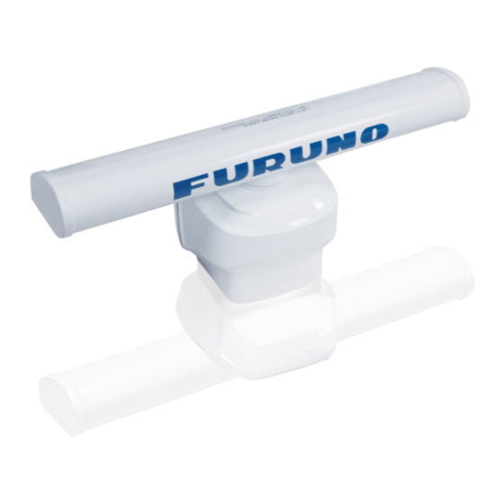
RADAR SENSOR
DRS6A X-Class
Model
SAFETY INSTRUCTIONS
SYSTEM CONFIGURATION
EQUIPMENT LISTS
1. INSTALLATION AND WIRING
1.1 Mounting Considerations
1.2 Included Items
1.3 Required Tools and Materials
1.4 Fastening the Radiator to the Radiator Bracket
1.5 Mounting the Antenna Unit
1.6 Wiring
2. INITIAL SETUP
2.1 Initial Setup for TZT9/TZT14/TZTBB
2.2 Initial Setup for TZTL12F/TZTL15F
3. MAINTENANCE, TROUBLE SHOOTING
3.1 Maintenance
3.2 Troubleshooting
3.3 Replacement of Fuse
3.4 Life of Parts
SPECIFICATIONS
OUTLINE DRAWING
INTERCONNECTION DIAGRAM
Advertisement
Table of Contents

Related Manuals for Furuno DRS6A X-Class


Summary of Contents for Furuno DRS6A X-Class
- Page 1 Installation Manual RADAR SENSOR DRS6A X-Class Model SAFETY INSTRUCTIONS SYSTEM CONFIGURATION EQUIPMENT LISTS 1. INSTALLATION AND WIRING 1.1 Mounting Considerations 1.2 Included Items 1.3 Required Tools and Materials 1.4 Fastening the Radiator to the Radiator Bracket 1.5 Mounting the Antenna Unit 1.6 Wiring...
-
Page 2: Safety Instructions
SAFETY INSTRUCTIONS The installer of the equipment must read the safety instructions before attempting to install the equipment. Indicates a potentially hazardous situation which, if not avoided, WARNING could result in death or serious injury. Indicates a potentially hazardous situation which, if not avoided, CAUTION can result in minor or moderate injury. - Page 3 Standard Steering Model the transmitting antenna at a compass compass close distance. DRS6A X-Class 1.40 m 0.90 m Distances at which RF radiation levels of 100, 50 and 10 W/m exist It is recommended that you are given in the table below.
-
Page 4: System Configuration
NavNet TZtouch/Navnet TZtouch 2 NavNet TZtouch/Navnet TZtouch 2 The DRS6A X-Class is compatible with the FURUNO Multi Function Displays and software ver- sion combinations shown below. The combination with other models may not operate properly. • TZT9, TZT14, and TZTBB: Version 4.21 or later (Planned release: Middle of 2016) -
Page 5: Equipment Lists
EQUIPMENT LISTS Standard supply Name Type Code No. Remarks Scanner Unit RSB-134-112 Radiator XN10A 3.4 ft XN12A 4 ft XN13A 6 ft Installation Materials CP03-37101 001-426-290 For scanner unit CP03-22901 008-523-690 For radiator CP03-36400 000-027-211 Cable assembly, 10 m CP03-36410 000-027-212 Cable assembly, 15 m CP03-36420... -
Page 6: Installation And Wiring
INSTALLATION AND WIRING NOTICE Do not apply paint, anti-corrosive sealant or contact spray to coating or plastic parts of the equipment. Those items contain organic solvents that can damage coating and plastic parts, especially plastic connectors. Mounting Considerations Select a mounting location, keeping in mind in the following points: •... - Page 7 1. INSTALLATION AND WIRING • In order to reduce electrical interference, avoid routing the power cable near other electrical equipment on-board. Also, avoid running the cable in parallel with other power cables. • It is not recommended to install the antenna unit on the hardtop of a cabin. Vibra- tions from the antenna unit will pass through the hardtop and into the cabin.
-
Page 8: Included Items
1. INSTALLATION AND WIRING Included Items Radiator • Radiator* (1 pcs): • Flat washer (M8, 4 pcs) • Spring washer (M8, 4 pcs) 3.4 ft, 4 ft or 6 ft • Hex. bolt (M8×30, 4 pcs) • O-ring (1 pcs) •... -
Page 9: Required Tools And Materials
1. INSTALLATION AND WIRING Required Tools and Materials The following tools should be prepared in advance for this installation. Name Remarks For making the mounting holes, drill bit: 15 mm Electrical drill Phillips-head screw driver #3, for securing the cable cover Wrench For M8 (Hex. -
Page 10: Fastening The Radiator To The Radiator Bracket
1. INSTALLATION AND WIRING Fastening the Radiator to the Radiator Bracket 1. Remove the radiator cap from the radiator bracket. Radiator bracket Radiator cap 2. Apply silicone rubber to the surface of the radiator bracket as shown in the figure below. - Page 11 1. INSTALLATION AND WIRING 4. Apply silicone rubber to the thread holes on the bottom of the radiator (4 loca- tions). Silicone rubber Bottom view: Radiator 5. Prepare four bolt assemblies; pass the spring washer (M8) and flat washer (M8) through the each hex bolt (M830) then apply silicone rubber.
-
Page 12: Mounting The Antenna Unit
1. INSTALLATION AND WIRING Mounting the Antenna Unit The antenna unit can be mounted using the fixing holes on the outside (200 200 mm) or inside (140 150 mm) the antenna unit. Normally, use the outside fixing holes. When 140 ... - Page 13 1. INSTALLATION AND WIRING 3. Apply silicone rubber to the thread of the stud bolts (M1270, 4 pcs). Note: Apply silicone rubber to the part of thte bolt threads that are inside the bolt hole (see the figure at step 4). 4.
- Page 14 1. INSTALLATION AND WIRING 6. Secure the antenna unit, using the supplied flat washers (M12, 4 pcs), spring washers (M12, 4 pcs), and hex. nuts (M12, 8 pcs). Flat washer Spring washer Hex. nut 7. Apply silicone rubber to the flat washers, spring washers, and hex. nuts. Detailed view Corrosion-proof rubber pad...
- Page 15 • When you replace the DRS4A/6A/12A/25A with the DRS6A X-Class, the existing cable cannot be used. Use only the cable assembly supplied with the DRS6A X- Class.
- Page 16 1. INSTALLATION AND WIRING 3. Wrap the junction of the connectors with self-vulcanizing tape and vinyl tape (local supply) for waterproofing as follows: 1) Wrap the junction of the connectors 2) Change wrap direction and wrap with one layer of self-vulcanizing one layer of the self-vulcanizing tape.
- Page 17 Cable cover - bottom view 8. Reattach the cable cover. 9. Connect the LAN connector of the cable assembly to a LAN port on the FURUNO Multi Function Display or Ethernet HUB. Note: Do not connect the LAN connector to on-board LAN.
- Page 18 1. INSTALLATION AND WIRING 10. Connect the power wires to the ship’s battery (24 VDC). • Red wire: Connect to the positive terminal. The red wire has the fuse holder. • Blue wire: Connect to the negative terminal. • Black wire: The black wire is a shielding wire for grounding. Fuse holder Distribution Blue...
-
Page 19: Initial Setup For Tzt9/Tzt14/Tztbb
• TZT9, TZT14, and TZTBB: Version 4.21 or later (Planned release: Middle of 2016) • TZTL12F and TZTL15F: Version 3.01 or later (Planned release: Middle of 2016) Turn on the antenna unit and FURUNO Multi Function Display. Initial setup for this an- tenna must be done on the FURUNO Multi Function Display. - Page 20 2. INITIAL SETUP 5. Drag the [Menu Radar] sub menus to find the menu item [Radar Initial Setup]. Title 6. Set the items referring to the table shown below Menu Radar (Radar Initial Setup) Menu item Description [Antenna Rotation] Select the antenna rotation speed. [Antenna Heading Align] See "How to align the antenna heading"...
- Page 21 2. INITIAL SETUP How to align the antenna heading You have mounted the antenna unit facing straight ahead in the direction of the bow. Therefore, a small but conspicuous target dead ahead visually should appear on the heading line (zero degrees). You may observe a minor bearing error on the display.
-
Page 22: Initial Setup For Tztl12F/Tztl15F
The name of the antenna unit should appear with a check mark, as in the example below. RDxxxxxx - DRS6A X-Class 4. Drag the [Radar] menu display the menu item [Radar Initial Setup], then tap [Radar Initial Setup]. - Page 23 2. INITIAL SETUP How to align the antenna heading You have mounted the antenna unit facing straight ahead in the direction of the bow. Therefore, a small but conspicuous target dead ahead visually should appear on the heading line (zero degrees). You may observe a minor bearing error on the display.
- Page 24 MAINTENANCE, TROUBLE SHOOTING Periodic checks and maintenance are important for proper operation of any electronic system. This chapter contains maintenance and troubleshooting instructions to be fol- lowed to obtain optimum performance and the longest possible life of the equipment. Before attempting any maintenance or troubleshooting procedure please review the safety information below and at the front of this manual.
-
Page 25: Maintenance
3. MAINTENANCE, TROUBLE SHOOTING Maintenance Regular maintenance is important for good performance. Check the points mentioned below every 3 to 6 months to keep the antenna unit in good working order. Check point Action Remedy, remarks Check points every 3 to 6 months Cable Check that all cables are firmly •... -
Page 26: Troubleshooting
3. MAINTENANCE, TROUBLE SHOOTING Troubleshooting The table below provides simple troubleshooting procedures to restore normal opera- tion. If you cannot restore normal operation, contact your dealer for advice. Problem Remedy The multi function display can- • Check that all cables are tightly fastened. not control the radar. -
Page 27: Life Of Parts
3. MAINTENANCE, TROUBLE SHOOTING Life of Parts Magnetron When a magnetron reaches the end of its life, target echoes become weak and do not appear on the display. If long-range performance appears to have declined, contact your dealer about replacement of the magnetron. Name Type Code No. - Page 28 FURUNO DRS6A X-Class SPECIFICATIONS OF RADAR SENSOR DRS6A X-Class ANTENNA UNIT Antenna type Slotted waveguide array Antenna length 3.4 ft (XN10A), 4 ft (XN12A), 6 ft (XN13A) Horizontal beam width 2.3° (XN10A), 1.9° (XN12A), 1.4° (XN13A) Vertical beam width 22°...
- Page 29 FURUNO DRS6A X-Class ENVIRONMENTAL CONDITIONS Ambient temperature -25°C to +55°C (storage: -30°C to +70°C) Relative humidity 95% or less at +40°C Degree of protection IP56 Vibration IEC 60945 Ed.4 UNIT COLOR N9.5...
- Page 31 MULTI FUNCTION DISPLAY TL-CAT-012 TZT9/14/BB TZTL12F/15F RJ45 ETHERNET HUB HUB-101 MULTI FUNCTION DISPLAY TZT9/14/BB,TZTL12F/15F VH2P-MVVS0.75x2C 12-24VDC NETWORK EQUIPMENT DRAWN TITLE DRS6A X-CLASS T.YAMASAKI 25/Jun/2015 CHECKED H.MAKI 25/Jun/2015 NOTE APPROVED *1: SHIPYARD SUPPLY. SCALE MASS NAME RADAR SENSOR *2: OPTION. DWG.No.
- Page 32 Installation Manual RADAR SENSOR DRS6A X-Class/DRS12A X-Class/DRS25A X-Class Model SAFETY INSTRUCTIONS SYSTEM CONFIGURATION EQUIPMENT LISTS 1. INSTALLATION AND WIRING 1.1 Mounting Considerations 1.2 Included Items 1.3 Required Tools and Materials 1.4 Fastening the Radiator to the Radiator Bracket 1.5 Mounting the Antenna Unit 1.6 Wiring...
- Page 33 SAFETY INSTRUCTIONS The installer of the equipment must read the safety instructions before attempting to install the equipment. Indicates a potentially hazardous situation which, if not avoided, WARNING could result in death or serious injury. Indicates a potentially hazardous situation which, if not avoided, CAUTION can result in minor or moderate injury.
- Page 34 Name: Warning Label (2) Type: 03-129-1001-3 Code No: 100-236-743 Importer in Europe The following concern acts as our importer in Europe, as defined in DECISION No 768/2008/EC. - Name: FURUNO EUROPE B.V. Program No. • 0359355-01.** ** denotes minor modifications.
- Page 35 Multi Function Display NavNet TZtouch/Navnet TZtouch 2 NavNet TZtouch/Navnet TZtouch 2 This radar series is compatible with the FURUNO Multi Function Displays and software version combinations shown below. The combination with other models may not operate properly. • DRS6A X-Class TZT9, TZT14 and TZTBB: Version 4.21 or later...
- Page 36 Cable assembly (30 m) and fuse (10 A) for re- CP03-37430 000-033-085 placement, supplied for DRS12A/25A X-Class Spare Parts SP03-18101 001-426-190 Fuse (5 A), supplied for DRS6A X-Class Fuse (10 A), supplied for DRS12A X-Class and SP03-18301 001-458-590 DRS25A X-Class *: Selectable for DRS6A X-Class only. Optional supply...
- Page 37 INSTALLATION AND WIRING NOTICE Do not apply paint, anti-corrosive sealant or contact spray to coating or plastic parts of the equipment. Those items contain organic solvents that can damage coating and plastic parts, especially plastic connectors. Mounting Considerations Select a mounting location, keeping in mind the following points: •...
- Page 38 Not recommended • Setup the antenna unit position on the FURUNO Multi Function Display after install- ing the unit, referring to the chapter 2. If the antenna unit position is not setup cor- rectly, the radar echoes on the display may not be aligned with the actual target’s...
- Page 39 10 m, 15 m, 20 m or 30 m • Fuse for replacement • Label (1 pcs) • How to Replace the Fuse (1 pcs) (1 pcs) : Select the appropriate length when purchasing. : Selectable for DRS6A X-Class only.
- Page 40 1. INSTALLATION AND WIRING Required Tools and Materials The following tools should be prepared in advance for this installation. Name Remarks Electrical drill For making the mounting holes, drill bit: 15 mm Phillips-head screw driver #3, for securing the cable cover Wrench For M8 (Hex.
- Page 41 1. INSTALLATION AND WIRING Fastening the Radiator to the Radiator Bracket 1. Remove the radiator cap from the radiator bracket. Radiator bracket Radiator cap 2. Apply silicone rubber to the surface of the radiator bracket as shown in the figure below.
- Page 42 1. INSTALLATION AND WIRING 4. Apply silicone rubber to the thread holes on the bottom of the radiator (4 loca- tions). Silicone rubber Bottom view: Radiator 5. Prepare four bolt assemblies; pass the spring washer (M8) and flat washer (M8) through the each hex bolt (M8 30) then apply silicone rubber.
- Page 43 1. INSTALLATION AND WIRING 7. Apply silicone rubber to the holes and bolts at the locations indicated with arrows in the figure below. Also apply silicone rubber to the junction between the radiator and the radiator bracket. Bolt assembly - side view (detailed) Radiator Apply silicone rubber Apply silicone rubber...
- Page 44 1. INSTALLATION AND WIRING 3. Apply silicone rubber to the thread of the stud bolts (M12 70, 4 pcs). Note: Apply silicone rubber to the part of thte bolt threads that are inside the bolt hole (see the figure at step 4). 4.
- Page 45 1. INSTALLATION AND WIRING • Hoist the antenna unit slowly. If the antenna unit is hoisted too quickly, the bracket can be damaged. 6. Place the antenna unit on the mounting platform with the BOW mark on the unit aligned with the ship’s bow. BOW mark BOW mark 7.
- Page 46 • When you replace the DRS4A/6A/12A/25A with the DRS6A X-Class/DRS12A X- Class/DRS25A X-Class, the existing cable cannot be used. Use only the cable as- sembly supplied with this radar sensor...
- Page 47 1. INSTALLATION AND WIRING 3. Wrap the junction of the connectors with self-vulcanizing tape and vinyl tape (local supply) for waterproofing as follows: 1) Wrap the junction of the connectors 2) Change wrap direction and wrap with one layer of self-vulcanizing one layer of the self-vulcanizing tape.
- Page 48 Cable cover - bottom view 8. Reattach the cable cover. 9. Connect the LAN connector of the cable assembly to a LAN port on the FURUNO Multi Function Display or Ethernet HUB. Note 1: Do not connect the LAN connector to on-board LAN.
- Page 49 1. INSTALLATION AND WIRING Note 2: When LAN cable extension is needed, use the optional LAN cable (MOD- Z072) and joint box (TL-CAT-012). After connection is completed, wrap the con- nector with vinyl tape to waterproof the LAN connector. Joint box 10.
-
Page 50: Initial Setup
TZT9, TZT14 and TZTBB: Version 5.01 or later (Planned release: End of 2016) TZTL12F and TZTL15F: Version 4.01 or later (Planned release: End of 2016) Turn on the antenna unit and FURUNO Multi Function Display. Initial setup for this an- tenna must be done on the FURUNO Multi Function Display. - Page 51 RDxxxxxx - DRS6A X-Class check mark, as in the example to the right. Display example for DRS6A X-Class 5. Drag the [Menu Radar] sub menus to find the menu item [Radar Initial Setup]. Title 6.
- Page 52 2. INITIAL SETUP Menu item Description [Antenna Longitudinal Po- Referring to the figure on the right, enter sition] the radar antenna positioning bow-stern Origin (Longitudinal) and port-starboard (Lateral) [Antenna Lateral Position (- position from the origin. Port)] [Auto Tuning] Enable/disable auto tuning for the connected radar. [Tuning Source] For dual-range display, select the range to use as the manual tuning source.
- Page 53 The name of the antenna unit should appear with a check mark, as in the example below. RDxxxxxx - DRS6A X-Class Display example for DRS6A X-Class 4. Drag the [Radar] menu display the menu item [Radar Initial Setup], then tap [Radar Initial Setup].
- Page 54 2. INITIAL SETUP 5. Referring to the tables below, set up the radar. [Radar] menu - [Radar Initial Setup] Menu item Description [Antenna Rotation] Select the antenna rotation speed. [Antenna Heading Align] See "How to align the antenna heading" on page 19. [Main Bang Suppression] If main bang appears at the screen center, slide the circle icon so that the main bang disappears, while watching the...
- Page 55 2. INITIAL SETUP How to align the antenna heading You have mounted the antenna unit facing straight ahead in the direction of the bow. Therefore, a small but conspicuous target dead ahead visually should appear on the heading line (zero degrees). You may observe a minor bearing error on the display.
- Page 56 2. INITIAL SETUP 2. Turn the vessel’s bow toward a target. 3. Tap the [Home] icon to show the home screen and display mode settings. 4. Tap [Radar] to show the [Radar] menu. 5. Drag the [Radar] menu to show the [RADAR INITIAL SETUP] menu. 6.
- Page 57 MAINTENANCE, TROUBLE SHOOTING Periodic checks and maintenance are important for proper operation of any electronic system. This chapter contains maintenance and troubleshooting instructions to be fol- lowed to obtain optimum performance and the longest possible life of the equipment. Before attempting any maintenance or troubleshooting procedure please review the safety information below and at the front of this manual.
- Page 58 3. MAINTENANCE, TROUBLE SHOOTING Maintenance Regular maintenance is important for good performance. Check the points mentioned below every 3 to 6 months to keep the antenna unit in good working order. Check point Action Remedy, remarks Check points every 3 to 6 months Cable Check that all cables are firmly •...
- Page 59 If the fuse blows again after the replacement, contact your dealer. Name Type Code No. Remarks Fuse FRU-2P5S-FU-5A-B 000-168-869-10 5 A fuse For DRS6A X-Class ATV10A60V 000-192-660-10 10 A fuse For DRS12A/25A X-Class Cable assembly WARNING WARNING Use the proper fuse.
- Page 60 Name Type Code No. Approx. Life Remarks Magnetron MAF1422B 000-158-788-12 5,000 hours For DRS6A X-Class FNE1201 001-245-890 5,000 hours For DRS12A X-Class MG5436 000-140-762-13 5,000 hours For DRS25A X-Class Antenna Motor When an antenna motor reaches the end of its life, the antenna’s rotation may stop or abnormal noise sounds from the antenna unit.
-
Page 61: Appendix 1 Radio Regulatory Information
• This equipment should be installed and operated keeping the radiator away from a person's body at the minimum distances shown in the table below. Antenna Model Transceiver Unit Safety Distance DRS6A X-Class RTR-112 300 cm DRS12A X-Class RTR-113 310 cm... - Page 62 Antenna length 3.4 ft (XN10A), 4 ft (XN12A), 6 ft (XN13A) Horizontal beam width 2.3° (XN10A), 1.9° (XN12A), 1.4° (XN13A) Radiator type XN10A for DRS6A X-Class only Vertical beam width 22° Gain 27.5 dBi (XN10A), 28.5 dBi (XN12A), 30 dBi (XN13A)
- Page 63 FURUNO DRS6A/12A/25A X-Class POWER SUPPLY DRS6A X-Class 24 VDC: 4.0 A DRS12A X-Class 24 VDC: 4.5 A DRS25A X-Class 24 VDC: 5.6 A ENVIRONMENTAL CONDITIONS Ambient temperature -25°C to +55°C (storage: -30°C to +70°C) Relative humidity 95% or less at +40°C...
- Page 71 22/Jun/2016 H.MAKI...
- Page 73 3/Aug/2016 H.MAKI Accept no compromises, choose only quality marine electronics and navigation.