Advertisement
Table of Contents
- 1 Table of Contents
- 2 Warning Decal Placement
- 3 Important Precautions
- 4 Before You Begin
- 5 Part Identification Chart
- 6 Assembly
- 7 Against the Crank (45
- 8 How to Use the Elliptical
- 9 Maintenance and Troubleshooting
- 10 Exercise Guidelines
- 11 Part List
- 12 Exploded Drawing
- 13 Ordering Replacement Parts
- 14 Recycling Information
- Download this manual
Model No. PFEL04915.0
Serial No.
Write the serial number in the
space above for reference.
Serial
Number
Decal
CUSTOMER SERVICE
UNITED KINGDOM
Call: 0330 123 1045
From Ireland: 053 92 36102
Website: iconsupport.eu
E-mail: csuk@iconeurope.com
Write:
ICON Health & Fitness, Ltd.
Unit 4, Westgate Court
Silkwood Park
OSSETT
WF5 9TT
UNITED KINGDOM
AUSTRALIA
Call: 1800 993 770
E-mail: australiacc@iconfitness.com
Write:
ICON Health & Fitness
PO Box 635
WINSTON HILLS NSW 2153
AUSTRALIA
CAUTION
Read all precautions and
instructions in this manual before
using this equipment. Keep this
manual for future reference.
USER'S MANUAL
iconeurope.com
Advertisement
Table of Contents

Related Manuals for Pro-Form 450 LE


Summary of Contents for Pro-Form 450 LE
- Page 1 Model No. PFEL04915.0 Serial No. USER’S MANUAL Write the serial number in the space above for reference. Serial Number Decal CUSTOMER SERVICE UNITED KINGDOM Call: 0330 123 1045 From Ireland: 053 92 36102 Website: iconsupport.eu E-mail: csuk@iconeurope.com Write: ICON Health & Fitness, Ltd. Unit 4, Westgate Court Silkwood Park OSSETT...
-
Page 2: Table Of Contents
TABLE OF CONTENTS WARNING DECAL PLACEMENT ............. . .2 IMPORTANT PRECAUTIONS . -
Page 3: Important Precautions
IMPORTANT PRECAUTIONS WARNING: To reduce the risk of serious injury, read all important precautions and instructions in this manual and all warnings on your elliptical before using your elliptical. ICON assumes no responsibility for personal injury or property damage sustained by or through the use of this product. -
Page 4: Before You Begin
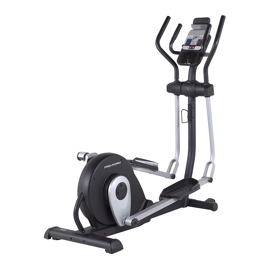
450 LE manual. To help us assist you, note the product model ® elliptical. The 450 LE elliptical provides an array of number and serial number before contacting us. The features designed to make your workouts at home model number and the location of the serial number more effective and enjoyable. -
Page 5: Part Identification Chart
PART IDENTIFICATION CHART Use the drawings below to identify the small parts needed for assembly. The number in parentheses below each drawing is the key number of the part, from the PART LIST near the end of this manual. The number following the key number is the quantity needed for assembly. -
Page 6: Assembly
ASSEMBLY • Assembly requires two persons. • In addition to the included tool(s), assembly requires the following tools: • Place all parts in a cleared area and remove the one Phillips screwdriver packing materials. Do not dispose of the packing materials until you finish all assembly steps. - Page 7 3. Remove the indicated screw (A) and the ship- ping bracket (B) from the Base (1). Discard the screw and the shipping bracket. Next, tighten the Base Foot (26) into the Base (1). 4. Orient the Rear Stabilizer (7) as indicated by the sticker.
-
Page 8: Against The Crank (45
5. Hold a Hub Cover (75) and a Crank Arm (36) against the Crank (45). Align the holes in the Hub Cover (75) and the Crank Arm (36) with the unused holes in the right side of the Crank (45). Insert four Hub Screws (87) into the Hub Cover (75) and the Crank Arm (36), and finger tighten the Hub Screws into the Crank (45). - Page 9 7. Identify the Right Upright Cover (17) and hold it against the right side of the Upright (3). Attach the Right Upright Cover (17) with two M4 x 16mm Round Head Screws (101). Attach the Left Upright Cover (39) in the same way.
- Page 10 9. Insert the Pulse Wires (118) upward through the Upright (3) as shown. 10. Attach the Tablet Holder (121) to the Console (5) with four #8 x 16mm Screws (112); start all the Screws, and then tighten them. 11. While a second person holds the Console (5) near the Upright (3), plug the Upper Wire Harness (48) and the Pulse Wires (118) into the Avoid pinching...
- Page 11 12. Attach the Upright Cap (4) to the Console (5) with two M4 x 16mm Round Head Screws (101). 13. Identify the Right Upper Body Arm (8) and the Right Upper Body Leg (11) and orient them as shown. Insert the Right Upper Body Arm (8) into the Right Upper Body Leg (11).
- Page 12 14. Using a small plastic bag to keep your fingers clean, apply a generous amount of the included grease to the Pivot Axle (74) and to two Wave Washers (111). Insert the Pivot Axle (74) into the Upright (3) and center it.
- Page 13 16. Identify the Right Pedal (13) and the Right Pedal Arm (14). Attach the Right Pedal (13) to the Right Pedal Arm (14) with two #10 x 51mm Screws (108), two #10 x 13mm Screws (104), and four #10 Washers (102); start all the Screws, and then tighten them.
- Page 14 18. Lift the latch (E) on the underside of the Right Pedal Arm (14), and set the Right Pedal Arm on the right Crank Bushing Sleeve (43). Release the lever, and make sure that the Right Pedal Arm (14) is securely connected to the Crank Bushing Sleeve (43).
-
Page 15: How To Use The Elliptical
HOW TO USE THE ELLIPTICAL HOW TO PLUG IN THE POWER ADAPTER IMPORTANT: If the elliptical has been exposed to cold temperatures, allow it to warm to room tem- perature before plugging in the power adapter. If you do not do this, you may damage the console displays or other electronic components. - Page 16 HOW TO EXERCISE ON THE ELLIPTICAL To dismount the elliptical, wait until the pedals (N) come to a complete stop. Note: The elliptical does To mount the elliptical, hold the upper body arms (L) or not have a free wheel; the pedals will continue to move until the flywheel stops.
- Page 17 CONSOLE DIAGRAM FEATURES OF THE CONSOLE In addition, the console offers a selection of preset workouts. Each preset workout automatically changes The advanced console offers an array of features the resistance of the pedals and prompts you to designed to make your workouts more effective and maintain a target speed as it guides you through an enjoyable.
- Page 18 HOW TO USE THE MANUAL MODE The upper display—This display will show your pedal- 1. Turn on the console. ing speed in revolutions per minute (RPM) and your Press any button or begin pedaling to turn on the power output in watts. The console.
- Page 19 To pause the console, stop pedaling. When the When your pulse is detected, your heart rate will be console is paused, the displays will pause. To con- shown in the upper display. For the most accurate tinue your workout, simply resume pedaling. heart rate reading, hold the contacts for at least 15 seconds.
- Page 20 HOW TO USE AN 8-WEEK WEIGHT-LOSS The speed meter will WORKOUT show two flashing bars that represent the target 1. Turn on the console. speed zone (B) for the segment; the target Press any button or begin pedaling to turn on the speed zone includes a console.
- Page 21 HOW TO USE A PRESET WORKOUT As you exercise, keep your pedaling speed within the target zone for the current segment by 1. Turn on the console. increasing or decreasing your pedaling speed or by increasing or decreasing the resistance of the Press any button or begin pedaling to turn on the pedals.
- Page 22 HOW TO USE THE SOUND SYSTEM HOW TO CONNECT YOUR TABLET TO THE CONSOLE To play music or audio books through the console sound system while you exercise, plug a 3.5 mm male The console supports BLUETOOTH connections to to 3.5 mm male audio cable (not included) into the tablets via the iFit Bluetooth Tablet app and to compat- jack on the console and into a jack on your personal ible heart rate monitors.
- Page 23 4. Record and track your workout information. THE SETTINGS MODE Follow the instructions in the iFit Bluetooth Tablet The console features a settings mode that allows you app to record and track your workout information. to select a unit of measurement for the console and to view console usage information.
-
Page 24: Maintenance And Troubleshooting
MAINTENANCE AND TROUBLESHOOTING MAINTENANCE HOW TO LEVEL THE ELLIPTICAL Regular maintenance is important for optimal If the elliptical rocks slightly on your floor during use, performance and to reduce wear. Inspect and properly turn one or both of the leveling feet (A) beneath the tighten all parts each time the elliptical is used. -
Page 25: Exercise Guidelines
EXERCISE GUIDELINES Burning Fat—To burn fat effectively, you must exer- WARNING: cise at a low intensity level for a sustained period of Before beginning this time. During the first few minutes of exercise, your or any exercise program, consult your physi- body uses carbohydrate calories for energy. - Page 26 SUGGESTED STRETCHES The correct form for several basic stretches is shown at the right. Move slowly as you stretch; never bounce. 1. Toe Touch Stretch Stand with your knees bent slightly and slowly bend forward from your hips. Allow your back and shoulders to relax as you reach down toward your toes as far as possible.
- Page 27 NOTES...
-
Page 28: Part List
PART LIST Model No. PFEL04915.0 R0617A Key No. Qty. Description Key No. Qty. Description Base Drive Belt Frame Flywheel Upright C-magnet Upright Cap Pillow Block Console Magnet Front Stabilizer Spring Rear Stabilizer Idler Right Upper Body Arm Idler Bracket Left Upper Body Arm Clamp Arm Cap Power Adapter... - Page 29 Key No. Qty. Description Key No. Qty. Description M4 x 16mm Round Head Screw M6 Nut #10 Washer M8 x 23mm Shoulder Screw M4 x 16mm Screw M8 x 80mm Bolt #10 x 13mm Screw Pulse Grip M4 x 32mm Round Head Screw Pulse Wire M8 x 31mm Shoulder Screw Right Handlebar...
-
Page 30: Exploded Drawing
EXPLODED DRAWING A Model No. PFEL04915.0 R0617A... - Page 31 EXPLODED DRAWING B Model No. PFEL04915.0 R0617A...
-
Page 32: Ordering Replacement Parts
ORDERING REPLACEMENT PARTS To order replacement parts, please see the front cover of this manual. To help us assist you, be prepared to provide the following information when contacting us: • the model number and serial number of the product (see the front cover of this manual) •...