Table of Contents
Advertisement
Model No. 831.23935.0
Serial No.
Write the serial number in the space
above for reference.
Serial Number Decal
•• Assembly
•• Operation
•• Maintenance
•• Part List and Drawing
Sears, Roebuck and Co.
Hoffman Estates, IL 60179
CAUTION
Read all precautions and instruc-
tions in this manual before using
this equipment. Keep this manual
for future reference.
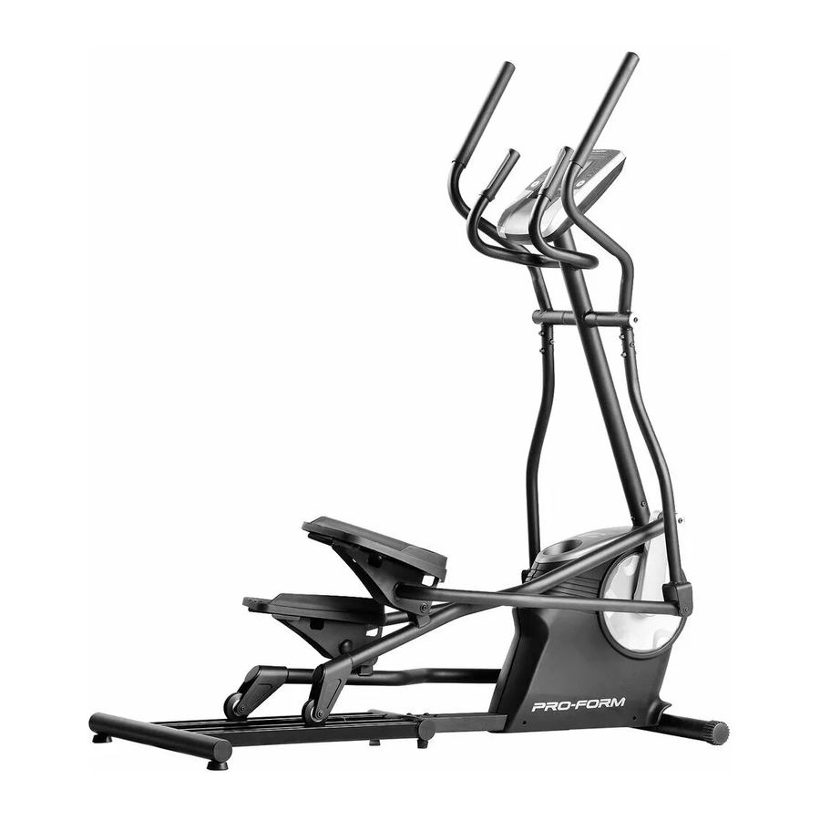
ELLIPTICAL EXERCISER
User’'s Manual
Advertisement
Table of Contents

Related Manuals for Pro-Form 475 E Elliptical


Summary of Contents for Pro-Form 475 E Elliptical
- Page 1 Model No. 831.23935.0 Serial No. ELLIPTICAL EXERCISER Write the serial number in the space User’’s Manual above for reference. Serial Number Decal •• Assembly •• Operation •• Maintenance •• Part List and Drawing Sears, Roebuck and Co. Hoffman Estates, IL 60179 CAUTION Read all precautions and instruc- tions in this manual before using...
-
Page 2: Table Of Contents
TABLE OF CONTENTS WARNING DECAL PLACEMENT ............. . . 2 IMPORTANT PRECAUTIONS . -
Page 3: Important Precautions
IMPORTANT PRECAUTIONS WARNING: To reduce the risk of serious injury, read all important precautions and instructions in this manual and all warnings on your elliptical before using your elliptical. Sears assumes no responsibility for personal injury or property damage sustained by or through the use of this product. -
Page 4: Before You Begin
Thank you for selecting the revolutionary PROFORM ® manual. To help us assist you, note the product model 475 E elliptical. The 475 E elliptical provides an number and serial number before contacting us. The impressive selection of features designed to make your model number and the location of the serial number workouts at home more effective and enjoyable. -
Page 5: Part Identification Chart
PART IDENTIFICATION CHART Use the drawings below to identify the small parts needed for assembly. The number in parentheses below each drawing is the key number of the part, from the PART LIST near the end of this manual. The number following the key number is the quantity needed for assembly. -
Page 6: Assembly
ASSEMBLY •• Assembly requires two persons. •• In addition to the included tool(s), assembly requires the following tools: •• Place all parts in a cleared area and remove the one Phillips screwdriver packing materials. Do not dispose of the packing materials until you ... - Page 7 3. With the help of a second person, place some of the packing materials (not shown) under the rear of the Frame (1). Attach the Track (11) to the Frame (1) with four M10 x 20mm Screws (74), two M10 x 39mm Screws (75), and six M10 Washers (64) as shown;...
- Page 8 5. Tip: Avoid pinching the Main Wire Harness (32). Slide the Upright (2) onto the Frame (1). Attach the Upright (2) with an M10 x 53mm Avoid pinching Screw (73), an M10 x 20mm Screw (74), two the Main Wire M10 Split Washers (80), and two M10 Curved Harness (32) Washers (62) as shown;...
- Page 9 7. Identify the Right Upper Body Arm (4) and the Right Upper Body Leg (5), and orient them as shown. Insert the Right Upper Body Arm (4) into the Right Upper Body Leg (5). Attach the Right Upper Body Arm with three M8 x 38mm Bolts (59) and three M8 Locknuts (60);...
- Page 10 9. Apply grease to the right Crank Arm (13). Identify the Right Roller Arm (7) and orient it as shown. Attach the Right Roller Arm (7) to the right Crank Arm (13) with an M8 x 20mm Screw (61), an Grease Axle Cover (44), and an M8 Washer (63).
- Page 11 11. Apply grease to a Short Axle (19). Slide the Right Pedal Arm (9) onto the Right Roller Arm (7) as shown, and insert the Short Axle (19) into both parts. Then, tighten an M8 x 20mm Screw (61) with an M8 Washer (63) into each end of the Short Axle (19) at the same time.
- Page 12 13. Remove and discard the wire tie on the Main Wire Harness (32). Have a second person hold the Console (30) near the Upright (2). Avoid pinching the wires Connect the wires on the Console (30) to the Main Wire Harness (32) and to the Pulse Wire Harness (31).
-
Page 13: How To Use The Elliptical
HOW TO USE THE ELLIPTICAL HOW TO MOVE THE ELLIPTICAL HOW TO EXERCISE ON THE ELLIPTICAL Due to the size and weight of the elliptical, moving To mount the elliptical, hold the handlebars or the it requires two persons. Stand in front of the elliptical, upper body arms and step onto the pedal that is in the hold the upright, and place one foot against one of the lower position. - Page 14 CONSOLE DIAGRAM FEATURES OF THE CONSOLE resistance of the pedals as it guides you through an effective workout. The advanced console offers an array of features designed to make your workouts more effective and You can even connect your MP3 player or CD player enjoyable.
-
Page 15: To Use The Manual Mode
HOW TO USE THE MANUAL MODE Profile——When a workout is selected, this display mode will show a profile of the resistance settings 1. Turn on the console. of the workout. Press any button or begin pedaling to turn on the Pulse——This display mode will show your heart rate console. -
Page 16: To Use A Preset Workout
5. Measure your heart rate if desired. HOW TO USE A PRESET WORKOUT If there are sheets 1. Turn on the console. of plastic on the metal contacts Press any button or begin pedaling to turn on the on the handgrip console. -
Page 17: Sound System
If the resistance level for the current segment is too 6. When you are finished exercising, the console high or too low, you can manually override the set- will turn off automatically. ting by pressing the Resistance buttons. However, when the current segment ends, the pedals will See step 6 on page 16. -
Page 18: To Grease The Rollers
MAINTENANCE AND TROUBLESHOOTING I nspect and tighten all parts of the elliptical regularly. Next, locate the Reed Switch (33). Turn the Pulley (15) Replace any worn parts immediately. until a Magnet (65) is aligned with the Reed Switch. To clean the elliptical, use a damp cloth and a small amount of mild soap. - Page 19 HOW TO ADJUST THE DRIVE BELT See EXPLODED DRAWING A on page 22. Remove the M4 x 25mm Screw (68) and the M4 x 16mm If the pedals slip while you are pedaling, even while Screws (56) from the Right and Left Shields (48, 49); the resistance is adjusted to the highest level, the drive make sure to note the location of each screw.
-
Page 20: Exercise Guidelines
EXERCISE GUIDELINES Burning Fat——To burn fat effectively, you must exer- WARNING: cise at a low intensity level for a sustained period of Before beginning this time. During the first few minutes of exercise, your or any exercise program, consult your physi- body uses carbohydrate calories for energy. -
Page 21: Part List
PART LIST Model No. 831.23935.0 R0813A Key No. Qty. Description Key No. Qty. Description Frame Wheel Upright Axle Cover Left Upper Body Arm Large Round Cap Right Upper Body Arm Right Pedal Right Upper Body Leg Left Pedal Left Upper Body Leg Right Shield Right Roller Arm Left Shield... -
Page 22: Exploded Drawing
EXPLODED DRAWING A Model No. 831.23935.0 R0813A... - Page 23 EXPLODED DRAWING B Model No. 831.23935.0 R0813A...
-
Page 24: 90 Day Full Warranty
90 DAY FULL WARRANTY If this Sears Elliptical Exerciser fails due to a defect in material or workmanship within 90 days of the date of purchase, call 1-800-4-MY-HOME ® (1-800-469-4663) to arrange for free repair (or replacement if repair proves impossible). The frame is warranted for 5 years. This warranty does not apply when the Elliptical Exerciser is used commercially or for rental purposes.