Agilent Technologies 1260 Infinity User Manual
Standard autosampler
Hide thumbs
Also See for 1260 Infinity:
- User manual (282 pages) ,
- Service manual (108 pages) ,
- Quick start manual (98 pages)
Table of Contents
Advertisement
Quick Links
Advertisement
Chapters
Table of Contents
Troubleshooting

Related Manuals for Agilent Technologies 1260 Infinity


Summary of Contents for Agilent Technologies 1260 Infinity
- Page 1 Agilent 1260 Infinity Standard Autosampler User Manual Agilent Technologies...
- Page 2 1987) or any equivalent agency regulation or contract clause. Use, duplication or dis- closure of Software is subject to Agilent Technologies’ standard commercial license terms, and non-DOD Departments and Agencies of the U.S. Government will Agilent 1260 Infinity Standard Autosampler User Manual...
- Page 3 In This Book In This Book This manual covers the Agilent 1260 Infinity Standard Autosampler (G1329B). 1 Introduction to the Autosampler This chapter gives an introduction to the autosampler, instrument overview and internal connectors. 2 Site Requirements and Specifications This chapter provides information on environmental requirements, physical and performance specifications.
- Page 4 This chapter provides information on parts for maintenance. 10 Identifying Cables This chapter provides information on cables used with the module. 11 Appendix This chapter provides addition information on safety, legal and web. Agilent 1260 Infinity Standard Autosampler User Manual...
-
Page 5: Table Of Contents
4 Using the Autosampler Sample Trays List of Compatible Vials and Caps 5 Optimizing Performance Optimization for Lowest Carry-over Fast Injection Cycle and Low Delay Volume Precise Injection Volume Choice of Rotor Seal Agilent 1260 Infinity Standard Autosampler User Manual... - Page 6 Introduction into Maintenance and Repair Maintenance Functions Simple Repairs 9 Parts and Materials for Maintenance Main Assemblies Analytical-Head Assembly Vial Trays Standard Autosampler Accessory Kit G1329-68755 Maintenance Kit G1313-68719 Multi-Draw Kit External Tray G1313-60004 Agilent 1260 Infinity Standard Autosampler User Manual...
- Page 7 CAN/LAN Cables Auxiliary Cable RS-232 Cables 11 Appendix General Safety Information The Waste Electrical and Electronic Equipment (WEEE) Directive (2002/96/EC) Lithium Batteries Information Radio Interference Solvent Information Sound Emission Agilent Technologies on Internet Agilent 1260 Infinity Standard Autosampler User Manual...
- Page 8 Contents Agilent 1260 Infinity Standard Autosampler User Manual...
-
Page 9: Introduction To The Autosampler
Agilent 1260 Infinity Standard Autosampler User Manual Introduction to the Autosampler Introduction to the Autosampler Sampling Sequence Sampling Unit Transport Assembly Early Maintenance Feedback (EMF) Instrument Layout Electrical Connections Serial Number Information (ALL) Electrical Connections Interfaces Overview Interfaces Setting the 8-bit Configuration Switch (On-Board LAN) -
Page 10: Introduction To The Autosampler
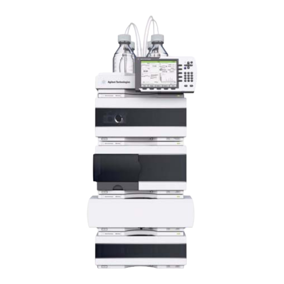
Figure 1 Overview of the Autosampler The Agilent 1260 Infinity autosamplers are designed for use with other modules of the Agilent 1200 Infinity Series, 1200 Series and 1100 Series LC system, or with other LC systems if adequate remote control inputs and outputs are available. - Page 11 Control of the vial temperature in the thermostatted autosampler is achieved using the autosampler thermostat G1330B. Details of this module are given in the Agilent 1290 Infinity Autosampler Thermostat manual. Agilent 1260 Infinity Standard Autosampler User Manual...
-
Page 12: Sampling Sequence
9 The gripper arm checks if the safety flap is in position. 10 The gripper arm replaces the vial, and returns to the home position. Simultaneously, the needle lowers into the seat. 11 The injection valve switches to the mainpass position. Agilent 1260 Infinity Standard Autosampler User Manual... - Page 13 When the sample sequence begins, the valve unit switches to the bypass position (Figure 3 on page 13). Solvent from the pump enters the valve unit at port 1, and flows directly to the column through port 6. Figure 3 Bypass Position Agilent 1260 Infinity Standard Autosampler User Manual...
- Page 14 The needle is lowered into the needle seat, and the injection valve switches back to the mainpass position, flushing the sample onto the column (Figure 5 on page 14). Figure 5 Mainpass Position (Sample Injection) Agilent 1260 Infinity Standard Autosampler User Manual...
-
Page 15: Sampling Unit
The sampling unit comprises three main assemblies: needle drive, metering device, and injection valve. The replacement sampling unit excludes the injection valve and metering head assemblies. N O T E Figure 6 Autosampler Sampling Unit Agilent 1260 Infinity Standard Autosampler User Manual... - Page 16 Standard (100 µL) Standard (900 µL) Number of steps 15000 15000 Volume resolution 7 nl/motor step 60 nl/motor step Maximum stroke 100 µL 900 µL Pressure limit 600 bar 400 bar Piston material Sapphire Sapphire Agilent 1260 Infinity Standard Autosampler User Manual...
- Page 17 No valve adjustments are required after replacing internal components. Table 2 Injection-Valve Technical Data Autosampler Motor type 4 V, 1.2 A stepper motor Seal material PEEK Stator material None Number of ports Switching time < 150 ms Agilent 1260 Infinity Standard Autosampler User Manual...
-
Page 18: Transport Assembly
The stepper motor positions are determined by the optical encoders mounted onto the stepper-motor housing. The encoders monitor the position of the Agilent 1260 Infinity Standard Autosampler User Manual... - Page 19 These positions are used by the processor to calculate the actual motor position. An additional six reflection sensors for tray recognition are mounted on the flex board at the front of the assembly. Agilent 1260 Infinity Standard Autosampler User Manual...
-
Page 20: Early Maintenance Feedback (Emf)
EMF limits, and then reset the EMF counters to zero. The next time the EMF counters exceed the new EMF limits, the EMF flag will be displayed, providing a reminder that maintenance needs to be scheduled. Agilent 1260 Infinity Standard Autosampler User Manual... -
Page 21: Instrument Layout
• the plastic layers help cushion the electronic and mechanical parts from physical shock, and • the metal inner cabinet shields the internal electronics from electromagnetic interference and also helps to reduce or eliminate radio frequency emissions from the instrument itself. Agilent 1260 Infinity Standard Autosampler User Manual... -
Page 22: Electrical Connections
There are no externally accessible fuses, because automatic electronic fuses are implemented in the power supply. Never use cables other than the ones supplied by Agilent Technologies to ensure proper N O T E functionality and compliance with safety or EMC regulations. -
Page 23: Serial Number Information (All)
Alphabetic character A-Z (used by manufacturing) Alpha-numeric code 0-9, A-Z, where each combination unambiguously denotes a module (there can be more than one code for the same module) 00000 Serial number Figure 8 Autosampler (plus Thermostat) Electrical Connections Agilent 1260 Infinity Standard Autosampler User Manual... -
Page 24: Interfaces
THERMOSTAT for G1364C FC-AS G1330B μ CAN-DC- OUT for CAN G1364D FC- slaves G1367E HiP ALS G1377A HiP micro ALS G2258A DL ALS G4226A ALS Detectors G1314B VWD VL G1314C VWD VL+ G1314E/F VWD Agilent 1260 Infinity Standard Autosampler User Manual... - Page 25 • CAN connectors as interface to other modules • LAN connector as interface to the control software • RS-232C as interface to a computer • REMOTE connector as interface to other Agilent products • Analog output connector(s) for signal output Agilent 1260 Infinity Standard Autosampler User Manual...
-
Page 26: Overview Interfaces
• one start bit and one stop bit are always used (not selectable). The RS-232C is designed as DCE (data communication equipment) with a 9-pin male SUB-D type connector. The pins are defined as: Agilent 1260 Infinity Standard Autosampler User Manual... - Page 27 RS-232C Connection Table Direction Function Ground Figure 9 RS-232 Cable Analog Signal Output The analog signal output can be distributed to a recording device. For details refer to the description of the module’s main board. Agilent 1260 Infinity Standard Autosampler User Manual...
- Page 28 APG Remote The APG Remote connector may be used in combination with other analytical instruments from Agilent Technologies if you want to use features as common shut down, prepare, and so on. Remote control allows easy connection between single instruments or systems to ensure coordinated analysis with simple coupling requirements.
- Page 29 (L) Request to start injection cycle (for example, by start key on any module). Receiver is the autosampler. Special Interfaces Some modules have module specific interfaces/connectors. They are described in the module documentation. Agilent 1260 Infinity Standard Autosampler User Manual...
-
Page 30: Setting The 8-Bit Configuration Switch (On-Board Lan)
Location of Configuration Switch (example shows a G4212A DAD) To perform any LAN configuration, SW1 and SW2 must be set to OFF. For details on the N O T E LAN settings/configuration refer to chapter LAN Configuration. Agilent 1260 Infinity Standard Autosampler User Manual... - Page 31 When selecting the mode TEST, the LAN settings are: Auto-Negotiation & Using Stored. N O T E For explanation of "Boot Resident System" and "Revert to Default Data (Coldstart)" refer to N O T E “Special Settings” on page 36. Agilent 1260 Infinity Standard Autosampler User Manual...
- Page 32 • for boot/test modes DIPS 1+2 must be UP plus required mode Switch settings provide configuration parameters for GPIB address, serial communication protocol and instrument specific initialization procedures. With the introduction of the Agilent 1260 Infinity, all GPIB interfaces have been removed. N O T E The preferred communication is LAN.
- Page 33 Baudrate Data Parity Bits Reserved Reserved TEST/BOOT RSVD RSVD RSVD The LAN settings are done on the LAN Interface Card G1369A/B. Refer to the N O T E documentation provided with the card. Agilent 1260 Infinity Standard Autosampler User Manual...
-
Page 34: Communication Settings For Rs-232C
Switches Baud Rate Switches Baud Rate 9600 9600 1200 14400 2400 19200 4800 38400 Table 10 Data Bit Settings (without on-board LAN) Switch 6 Data Word Size 7 Bit Communication 8 Bit Communication Agilent 1260 Infinity Standard Autosampler User Manual... - Page 35 No Parity Odd Parity Even Parity One start bit and one stop bit are always used (not selectable). Per default, the module will turn into 19200 baud, 8 data bit with no parity. Agilent 1260 Infinity Standard Autosampler User Manual...
-
Page 36: Special Settings
It only uses basic functions of the operating system for example, for communication. In this mode the main firmware can be loaded (using update utilities). Table 12 Boot Resident Settings (without on-board LAN) Mode Select TEST/BOOT No LAN TEST/BOOT Agilent 1260 Infinity Standard Autosampler User Manual... - Page 37 If you use the following switch settings and power the instrument up again, a forced cold start has been completed. Table 13 Forced Cold Start Settings (without on-board LAN) Mode Select TEST/BOOT No LAN TEST/BOOT Agilent 1260 Infinity Standard Autosampler User Manual...
- Page 38 Introduction to the Autosampler Setting the 8-bit Configuration Switch (On-Board LAN) Agilent 1260 Infinity Standard Autosampler User Manual...
-
Page 39: Site Requirements And Specifications
Agilent 1260 Infinity Standard Autosampler User Manual Site Requirements and Specifications Site Requirements Physical Specifications Performance Specifications Standard Autosampler This chapter provides information on environmental requirements, physical and performance specifications. Agilent Technologies... -
Page 40: Site Requirements
Hazard of electrical shock or damage of your instrumentation WA R N I N G can result, if the devices are connected to a line voltage higher than specified. ➔ Connect your instrument to the specified line voltage only. Agilent 1260 Infinity Standard Autosampler User Manual... - Page 41 Never operate your instrumentation from a power outlet that has no ground connection. ➔ Never use a power cord other than the Agilent Technologies power cord designed for your region. Use of unsupplied cables WA R N I N G Using cables not supplied by Agilent Technologies can lead to damage of the electronic components or personal injury.
- Page 42 Using power cords for unintended purposes can lead to personal injury or damage of electronic equipment. ➔ Never use the power cords that Agilent Technologies supplies with this instrument for any other equipment. Bench Space The autosampler dimensions and weight (see...
- Page 43 ➔ If your module was shipped in cold weather, leave it in its box and allow it to warm slowly to room temperature to avoid condensation. Agilent 1260 Infinity Standard Autosampler User Manual...
-
Page 44: Physical Specifications
WA R N I N G Using the autosampler at high environmental temperatures may cause the rear panel to become hot. ➔ Do not use the autosampler at environmental temperatures higher than 50 °C (122 °F) Agilent 1260 Infinity Standard Autosampler User Manual... -
Page 45: Performance Specifications Standard Autosampler
Site Requirements and Specifications Performance Specifications Standard Autosampler Performance Specifications Standard Autosampler Table 15 Performance Specifications Agilent 1260 Infinity Standard Autosampler (G1329B) Type Specification Pressure Operating range 0 - 60 MPa (0 - 600 bar, 0 - 8850 psi) GLP features... - Page 46 Site Requirements and Specifications Performance Specifications Standard Autosampler Agilent 1260 Infinity Standard Autosampler User Manual...
-
Page 47: Installing The Autosampler
Agilent 1260 Infinity Standard Autosampler User Manual Installing the Autosampler Unpacking the Autosampler Optimizing the Stack Configuration Installing the Autosampler Installing the Thermostatted Autosampler Flow Connections Installing the Sample Tray Transporting the Autosampler This chapter provides information on unpacking, checking on completeness, stack considerations and installation of the module. -
Page 48: Unpacking The Autosampler
Unpacking the Autosampler Damaged Packaging If the delivery packaging shows signs of external damage, please call your Agilent Technologies sales and service office immediately. Inform your service representative that the instrument may have been damaged during shipment. "Defective on arrival" problems C A U T I O N If there are signs of damage, please do not attempt to install the module. -
Page 49: Optimizing The Stack Configuration
Figure 15 page 52 show the configuration recommended for a thermostatted autosampler. These configurations optimize the system flow path, ensuring minimum delay volume. Figure 12 Recommended Stack Configuration for an Autosampler (Front View) Agilent 1260 Infinity Standard Autosampler User Manual... - Page 50 Installing the Autosampler Optimizing the Stack Configuration Figure 13 Recommended Stack Configuration for an Autosampler (Rear View) Agilent 1260 Infinity Standard Autosampler User Manual...
- Page 51 Installing the Autosampler Optimizing the Stack Configuration Figure 14 Recommended Stack Configuration for a thermostatted ALS (Front View) Agilent 1260 Infinity Standard Autosampler User Manual...
- Page 52 Installing the Autosampler Optimizing the Stack Configuration Figure 15 Recommended Stack Configuration for a thermostatted ALS (Rear View) Agilent 1260 Infinity Standard Autosampler User Manual...
-
Page 53: Installing The Autosampler
Do not bend the safety flap away from its position, or attempt to remove the safety cover (see Figure 16 on page 54). ➔ Do not attempt to insert or remove a vial from the gripper when the gripper is positioned below the needle. Agilent 1260 Infinity Standard Autosampler User Manual... - Page 54 7 Connect the CAN cable to the other Agilent 1200 Series modules. 8 If an Agilent Chemstation is the controller, connect either • The GPIB cable to the detector • The LAN connector to the LAN interface Agilent 1260 Infinity Standard Autosampler User Manual...
- Page 55 The sampler is turned ON when the line power switch is pressed and the green indicator N O T E lamp is illuminated. The detector is turned OFF when the line power switch is protruding and the green light is OFF. Agilent 1260 Infinity Standard Autosampler User Manual...
-
Page 56: Installing The Thermostatted Autosampler
➔ Make sure the power cords are unplugged before disconnecting or reconnecting the autosampler to ALS thermostat cable. Agilent 1260 Infinity Standard Autosampler User Manual... - Page 57 Condensation Leak outlet 3 Install the LAN interface board in the sampler (if required). 4 Remove the adhesive tape which covers the front door. 5 Remove the front door and remove the transport protection foam. Agilent 1260 Infinity Standard Autosampler User Manual...
- Page 58 13 If an Agilent ChemStation is the controller, connect either • The GPIB cable to the detector • The LAN connector to the LAN interface 14 Connect the APG remote cable (optional) for non Agilent 1200 Series instruments. Agilent 1260 Infinity Standard Autosampler User Manual...
- Page 59 The sampler is turned ON when the line power switch is pressed and the green indicator N O T E lamp is illuminated. The detector is turned OFF when the line power switch is protruding and the green light is OFF. Figure 20 Cable Connections Agilent 1260 Infinity Standard Autosampler User Manual...
-
Page 60: Flow Connections
4 Ensure that the waste tube is positioned inside the leak channel. Do not extend the waste capillary of the autosampler. The siphoning effect might empty the N O T E complete seat capillary introducing air into the system. Agilent 1260 Infinity Standard Autosampler User Manual... - Page 61 Installing the Autosampler Flow Connections Figure 21 Hydraulic Connections Agilent 1260 Infinity Standard Autosampler User Manual...
-
Page 62: Installing The Sample Tray
4 Press the front of the sample tray down to secure the tray in the autosampler. If the thermostatted autosampler tray pops out of position the air channel adapter is not N O T E inserted correctly. Figure 22 Installing the Sample Tray Agilent 1260 Infinity Standard Autosampler User Manual... -
Page 63: Transporting The Autosampler
Also, ensure the vial tray is secured in place with suitable packaging, otherwise the tray may become loose and damage internal components. Agilent 1260 Infinity Standard Autosampler User Manual... - Page 64 Installing the Autosampler Transporting the Autosampler Agilent 1260 Infinity Standard Autosampler User Manual...
- Page 65 Agilent 1260 Infinity Standard Autosampler User Manual Using the Autosampler Sample Trays List of Compatible Vials and Caps This chapter provides information on how to set up the module for an analysis and explains the basic settings. Agilent Technologies...
-
Page 66: Using The Autosampler Sample Trays
The vial positions of the right-hand half tray begin at position 101 as follows: Left-hand 40-position tray: 1 - 40 Left-hand 15-position tray: 1–15 Right-hand 40-position tray: 101–140 Right-hand 15-position tray: 101–115 Agilent 1260 Infinity Standard Autosampler User Manual... - Page 67 Using the Autosampler Sample Trays Figure 23 Numbering of Tray Positions Agilent 1260 Infinity Standard Autosampler User Manual...
-
Page 68: List Of Compatible Vials And Caps
Crimp Top Vial, 2 mL, amber glass, write-on spot, 100/Pack (silanized) 5182-0567 Crimp Top Vial, 1 mL, polypropylene, wide opening, 100/Pack 5183-4496 Crimp Top Vial, 1 mL, polypropylene, wide opening, 100/Pack (silanized) 9301-0978 crimp top vial, 0.3 mL, polypropylene, wide opening, 1000/pack Agilent 1260 Infinity Standard Autosampler User Manual... - Page 69 Screw Cap Vial, 2 mL, amber glass, write-on spot, 100/pk 5183-2069 Screw Top Vial, 2 mL, amber glass, write-on spot, 1000/Pack 5183-2072 Screw Top Vial, 2 mL, amber glass, write-on spot, 100/Pack (silanized) Agilent 1260 Infinity Standard Autosampler User Manual...
- Page 70 Screw Cap, red polypropylene, septum (clear PTFE/red rubber), 100/Pack 5182-0720 Screw Cap, blue polypropylene, septum (clear PTFE/silicone), 100/Pack 5182-0721 Screw Cap, green polypropylene, septum (clear PTFE/silicone), 100/Pack 5182-0722 Screw Cap, red polypropylene, septum (clear PTFE/silicone), 100/Pack Agilent 1260 Infinity Standard Autosampler User Manual...
-
Page 71: Optimizing Performance
Agilent 1260 Infinity Standard Autosampler User Manual Optimizing Performance Optimization for Lowest Carry-over Using the Automated Needle Wash Using an Injector Program General Recommendation to Lowest Carry-over Fast Injection Cycle and Low Delay Volume Overlapped Injection Mode General Recommendations for Fast Injection Cycle Times... -
Page 72: Optimization For Lowest Carry-Over
If the wash vial is capped, small amounts of sample remain on the surface of the septum, which may be carried on the needle to the next sample. Agilent 1260 Infinity Standard Autosampler User Manual... -
Page 73: Using An Injector Program
Outside wash of needle in vial 7 before injection Injector program: Draw x.x (y) µl from sample NEEDLE WASH vial 7 Inject Wait (equilibration time - see text above) Valve bypass Wait 0.2 min Valve mainpass Agilent 1260 Infinity Standard Autosampler User Manual... -
Page 74: General Recommendation To Lowest Carry-Over
If this is not known use 2 or 3 solvents of different polarity. Use several milliliters to clean the seat. • Clean the needle seat with a tissue and remove all liquid from it. • RESET the injector. Agilent 1260 Infinity Standard Autosampler User Manual... -
Page 75: Fast Injection Cycle And Low Delay Volume
100 µl instead of 1 µl, increase the injection time by approximately 8 sec. In this case and if the viscosity of the sample allows it, the draw and eject speed of the injection system has to be increased. Agilent 1260 Infinity Standard Autosampler User Manual... -
Page 76: General Recommendations For Fast Injection Cycle Times
• Increase of draw and eject speed for large injection volumes • Add at last run a blank, if overlapped injection is used To reduce the injection time, the detector balance has to be set to OFF. Agilent 1260 Infinity Standard Autosampler User Manual... -
Page 77: Precise Injection Volume
When using injection volumes < 2 µL, these gas bubbles may affect the injection-volume precision. For best injection-volume precision with injection volumes < 2 µL, use of an Agilent 1260 Infinity degasser is recommended to ensure the mobile phase is adequately degassed. - Page 78 An EJECT statement in an injector program also uses the eject speed setting which is configured for the autosampler. A faster eject speed shortens the time required to run the injector program. When using viscous samples, a high eject speed should be avoided. Agilent 1260 Infinity Standard Autosampler User Manual...
-
Page 79: Choice Of Rotor Seal
1 and 14. This seal is also used for the G1329B module. Strong oxidizing acids such as concentrated nitric and sulfuric acids are not compatible N O T E with PEEK. Agilent 1260 Infinity Standard Autosampler User Manual... - Page 80 Optimizing Performance Choice of Rotor Seal Agilent 1260 Infinity Standard Autosampler User Manual...
-
Page 81: Troubleshooting And Diagnostics
Agilent 1260 Infinity Standard Autosampler User Manual Troubleshooting and Diagnostics Overview of the Sampler’s Indicators and Test Functions Status Indicators Power Supply Indicator Module Status Indicator Maintenance Functions User Interface Change Needle Change Piston Park Arm Change Gripper Tray Alignment... -
Page 82: Overview Of The Sampler's Indicators And Test Functions
The step functions provide the possibility to execute each step of the sampling sequence individually. The step functions are used primarily for troubleshooting, and for verification of correct autosampler operation after repair (see “Standard Autosampler Step Commands” on page 92). Agilent 1260 Infinity Standard Autosampler User Manual... -
Page 83: Status Indicators
Figure 24 Location of Status Indicators Power Supply Indicator The power supply indicator is integrated into the main power switch. When the indicator is illuminated (green) the power is ON. Agilent 1260 Infinity Standard Autosampler User Manual... -
Page 84: Module Status Indicator
(modules without on-board LAN) indicator indicates that the module is in boot loader mode (e.g. during update of main firmware). In such a case try to re-boot the module or try a cold-start. Agilent 1260 Infinity Standard Autosampler User Manual... -
Page 85: Maintenance Functions
Change Gripper: The change gripper function moves the gripper to the front of the autosampler enabling easy access to the gripper release mechanism. Agilent 1260 Infinity Standard Autosampler User Manual... -
Page 86: Change Needle
The lowest position (end position) is used to align the needle at the correct position in the needle seat. Completes the procedure by moving the gripper arm to the home position, and releasing the safety flap. Agilent 1260 Infinity Standard Autosampler User Manual... -
Page 87: Change Piston
User Interface The commands for the control software are: Start Draws the piston away from the home position, relieving the tension on the spring. Repositions the piston at the home position. Agilent 1260 Infinity Standard Autosampler User Manual... - Page 88 1 Select Start to move the piston to the maintenance position. 2 Exchange the metering seal (see “Gripper Arm” on page 143). 3 Select End to move the piston back to the home position. Agilent 1260 Infinity Standard Autosampler User Manual...
-
Page 89: Park Arm
N O T E Gripper function to remove the vial. 1 Select Park Arm. 2 When the arm is in the park position, the autosampler is ready for shipment, and can be switched OFF. Agilent 1260 Infinity Standard Autosampler User Manual... -
Page 90: Change Gripper
1 Select Start to move the gripper arm to the maintenance position. 2 Exchange the gripper arm (see “Gripper Arm” on page 143). 3 Select End to move the gripper arm to the home position. Agilent 1260 Infinity Standard Autosampler User Manual... -
Page 91: Tray Alignment
Because the tray is a rectangle, a two-point alignment is sufficient to correct all other vial positions within the tray. On completion of the procedure, the corrected gripper positions are stored in the instrument firmware. Agilent 1260 Infinity Standard Autosampler User Manual... -
Page 92: Standard Autosampler Step Commands
Command can be done more than once (maximum draw volume of 100µl cannot be exceeded). Use Plunger Home to reset the metering device. Agilent 1260 Infinity Standard Autosampler User Manual... - Page 93 Needle into Seat Lowers the needle arm into the seat. Command also returns the vial to the tray position. Valve Mainpass Switches the injection valve to the mainpass position. Reset Resets the injector. Agilent 1260 Infinity Standard Autosampler User Manual...
-
Page 94: Troubleshooting
Sum of all draw volumes exceeds 100µl. Defective metering-drive motor. Needle Up Needle already in the upper position. Needle already in the upper position. Defective or dirty sensor on the sampling-unit flex board. Sticking needle-arm assembly. Defective needle-drive motor. Agilent 1260 Infinity Standard Autosampler User Manual... - Page 95 Blockage in the sample loop or needle (no solvent flow). Needle already in the upper position. Defective or dirty sensor on the sampling-unit flex board. Sticking needle-arm assembly. Defective needle-drive motor.Valve already in mainpass. Valve not connected. Defective injection valve. Agilent 1260 Infinity Standard Autosampler User Manual...
-
Page 96: Troubleshooting Guide For The Sample Transport Assembly
• motor overtemp (0 or 2 or 3) • movement failed (0 or 2 or 3) • missing vial Motor 0=X; 1=Z; 2=Theta; 3=Gripper. N O T E Agilent 1260 Infinity Standard Autosampler User Manual... -
Page 97: Intermittent Lock-Ups With Or Without Vial In The Gripper Fingers
Module and the ChemStation. To reset the transport alignment with the ChemStation, enter following command in the command line. Print sendmodule$(lals, “tray:alig 0.00,0.00”) 6 Check the tension of the belts. For this use the Torque2.mac and measure the torque for each axis. Agilent 1260 Infinity Standard Autosampler User Manual... - Page 98 9 Exchange the sample transport assembly (new Transport assembly (p/n G1329-60009) or refurbished exchange part Transport assembly for G1329A - G2260A (refurbished) (p/n G1329-69009)). 10 Exchange the main board (part number G1329-69520). Agilent 1260 Infinity Standard Autosampler User Manual...
-
Page 99: Jittery (Shaky) Movement In X And/Or Theta Axes And/Or When The Needle Goes Through The Gripper Arm Into The Vial
To avoid this, apply some grease from the sample transport repair kit to the X-motor-gear. Do not use other grease as the one in the kit and carefully follow the instruction from the N O T E technical note. Agilent 1260 Infinity Standard Autosampler User Manual... - Page 100 Chemstation enter following command in the command line: Print sendmodule$(lals, “tray:alig 0.00,0.00”) 7 Exchange the sample transport assembly (new exchange part G1329-60009 or refurbished exchange part G1329-69009). 8 Exchange the main board (part number G1329-69520). Agilent 1260 Infinity Standard Autosampler User Manual...
-
Page 101: Poor Alignment
4 Check the tension of the belts. For this use the Torque2.mac and measure the torque for each axis. Table 21 Typical ranges Theta (both) 30-50 X-axis (both) 50-90 Z-axis (both) 90-130 Gripper open 30-65 Gripper closed maximum 30 Agilent 1260 Infinity Standard Autosampler User Manual... - Page 102 Torque2.mac macro. Repeat this steps until the values are in the appropriate torque range. 7 Exchange the sample transport assembly (new exchange part G1329-60009 or refurbished exchange part G1329-69009). 8 Exchange the main board (part number G1329-69520). Agilent 1260 Infinity Standard Autosampler User Manual...
-
Page 103: Agilent Lab Advisor Software
Agilent Lab Advisor software may differ from the descriptions in this manual. For details refer to the Agilent Lab Advisor software help files. This manual provides lists with the names of Error Messages, Not Ready messages, and other common issues. Agilent 1260 Infinity Standard Autosampler User Manual... - Page 104 Troubleshooting and Diagnostics Agilent Lab Advisor Software Agilent 1260 Infinity Standard Autosampler User Manual...
-
Page 105: Error Information
Agilent 1260 Infinity Standard Autosampler User Manual Error Information What are Error Messages General Error Messages Timeout Shut-Down Remote Timeout Synchronization Lost Leak Leak Sensor Open Leak Sensor Short Compensation Sensor Open Compensation Sensor Short Fan Failed Open Cover Restart Without Cover... - Page 106 Agilent Lab Advisor Software Vial in Gripper Missing Wash Vial Invalid Vial Position This chapter describes the meaning of error messages, and provides information on probable causes and suggested actions how to recover from error conditions. Agilent 1260 Infinity Standard Autosampler User Manual...
-
Page 107: What Are Error Messages
This section describes the meaning of autosampler error messages, and provides information on probable causes and suggested actions how to recover from error conditions. Agilent 1260 Infinity Standard Autosampler User Manual... -
Page 108: General Error Messages
Check the logbook for the occurrence and A not-ready condition was present during a source of a not-ready condition. Restart the sequence or multiple-injection run for a analysis where required. period longer than the timeout threshold. Agilent 1260 Infinity Standard Autosampler User Manual... -
Page 109: Shut-Down
Check the vacuum degasser for an error The degasser failed to generate sufficient condition. Refer to the Service Manual for the vacuum for solvent degassing. degasser or the 1260 pump that has the degasser built-in. Agilent 1260 Infinity Standard Autosampler User Manual... -
Page 110: Remote Timeout
• Ensure all CAN cables are installed correctly. Exchange the CAN cable. Defective CAN cable. Switch off the system. Restart the system, and Defective main board in another module. determine which module or modules are not recognized by the system. Agilent 1260 Infinity Standard Autosampler User Manual... -
Page 111: Leak
Ensure the leak sensor is connected correctly. Leak sensor not connected to the main board. Exchange the leak sensor. Defective leak sensor. Exchange the leak sensor. Leak sensor incorrectly routed, being pinched by a metal component. Agilent 1260 Infinity Standard Autosampler User Manual... -
Page 112: Leak Sensor Short
If the resistance across the sensor increases above the upper limit, the error message is generated. Probable cause Suggested actions Exchange the main board. Defective main board. Agilent 1260 Infinity Standard Autosampler User Manual... -
Page 113: Compensation Sensor Short
This limit is given by 2 revolutions/second for longer than 5 seconds. Probable cause Suggested actions Ensure the fan is connected correctly. Fan cable disconnected. Exchange fan. Defective fan. Exchange the main board. Defective main board. Agilent 1260 Infinity Standard Autosampler User Manual... -
Page 114: Open Cover
30 s, and the error message is generated. Probable cause Suggested actions Reinstall the top cover and foam. The module started with the top cover and foam removed. Agilent 1260 Infinity Standard Autosampler User Manual... -
Page 115: Autosampler Error Messages
High friction in the transport assembly. representative. Please contact your Agilent service Defective motor assembly. representative. Please contact your Agilent service Defective sample transport assembly flex representative. board. Please contact your Agilent service Defective main board. representative. Agilent 1260 Infinity Standard Autosampler User Manual... -
Page 116: Valve To Bypass Failed
If the valve fails to reach the mainpass position, or if the microswitch does not close, the error message is generated. Probable cause Suggested actions Exchange the injection valve. Defective injection valve. Please contact your Agilent service Defective ASM board. representative. Agilent 1260 Infinity Standard Autosampler User Manual... -
Page 117: Needle Up Failed
Exchange the sampling unit flex board. Defective or dirty position sensor. Please contact your Agilent service Defective motor. representative. Please contact your Agilent service Sticking spindle assembly. representative. Please contact your Agilent service Defective ASM board. representative. Agilent 1260 Infinity Standard Autosampler User Manual... -
Page 118: Needle Down Failed
Exchange the sampling unit flex board. Defective or dirty position sensor. Please contact your Agilent service Defective motor. representative. Please contact your Agilent service Sticking spindle assembly. representative. Please contact your Agilent service Defective ASM board. representative. Agilent 1260 Infinity Standard Autosampler User Manual... -
Page 119: Missing Vial
Align gripper. Incorrect gripper alignment. Exchange the gripper assembly. Defective gripper assembly (defective gripper fingers or belt). Please contact your Agilent service Defective transport assembly flex board. representative. Agilent 1260 Infinity Standard Autosampler User Manual... -
Page 120: Initialization Failed
Exchange the sampling unit flex board. Dirty or defective sensor. Exchange the metering piston and seal. Broken piston. Please contact your Agilent service Defective metering-drive motor. representative. Please contact your Agilent service Defective ASM board. representative. Agilent 1260 Infinity Standard Autosampler User Manual... -
Page 121: Motor Temperature
Motor belt tension too high. switch. Wait at least 10 minutes before switching on again. Please contact your Agilent service Defective motor. representative. Please contact your Agilent service Defective transport assembly flex board. representative. Agilent 1260 Infinity Standard Autosampler User Manual... -
Page 122: Initialization With Vial
If the gripper is able to move beyond the safety flap position (safety flap not in position), the error message is generated. Probable cause Suggested actions Exchange the safety flap. Safety flap missing or broken. Agilent 1260 Infinity Standard Autosampler User Manual... - Page 123 Probable cause Suggested actions Install the wash vial in the correct position, or No wash vial in the position defined in the edit the method accordingly. method. Agilent 1260 Infinity Standard Autosampler User Manual...
- Page 124 Ensure the coding surfaces of the sample tray Tray recognition defective (dirty sample tray are clean (located at the rear of the sample tray). or defective transport assembly flex board). Agilent 1260 Infinity Standard Autosampler User Manual...
-
Page 125: Maintenance
Agilent 1260 Infinity Standard Autosampler User Manual Maintenance Introduction into Maintenance and Repair Simple Repairs Exchanging Internal Parts Safety Flap, Flex Board Transport Assembly Parts Updating the Firmware Warnings and Cautions Using the ESD Strap Cleaning the Module Maintenance Functions... -
Page 126: Introduction Into Maintenance And Repair
Safety Flap, Flex Board It is strongly recommended that the exchange of the safety flap, and flex board is done by Agilent-trained service personnel. Figure 25 Safety Flap Agilent 1260 Infinity Standard Autosampler User Manual... -
Page 127: Transport Assembly Parts
Do not connect the power cable to the Instrument while the covers are removed. Using the ESD Strap Electronic boards are sensitive to electrostatic discharge (ESD). In order to prevent damage, always use an ESD strap when handling electronic boards and components. Agilent 1260 Infinity Standard Autosampler User Manual... -
Page 128: Cleaning The Module
WA R N I N G Liquid in the module electronics can cause shock hazard and damage the module. ➔ Do not use an excessively damp cloth during cleaning. ➔ Drain all solvent lines before opening any fittings. Agilent 1260 Infinity Standard Autosampler User Manual... -
Page 129: Maintenance Functions
The maintenance functions move these assemblies into the appropriate maintenance position. For details, refer to “Maintenance Functions” on page 85. Agilent 1260 Infinity Standard Autosampler User Manual... -
Page 130: Simple Repairs
Exchanging the When autosampler reproducibility 30 minutes “Metering Seal and Piston” metering seal indicates seal wear page 139 Exchanging the gripper When the gripper arm is defective 10 minutes “Gripper Arm” on page 143 Agilent 1260 Infinity Standard Autosampler User Manual... -
Page 131: Needle Assembly
Do not bend the safety flap away from its position, or attempt to remove the safety cover (see Figure 16 on page 54). ➔ Do not attempt to insert or remove a vial from the gripper when the gripper is positioned below the needle. Agilent 1260 Infinity Standard Autosampler User Manual... - Page 132 Remove the sample-loop fitting from the needle fitting. with the hole in the safety cover. Loosen the fixing screw, and lift out the needle. Insert the new needle. Align the needle in the seat, then tighten the screw firmly. Agilent 1260 Infinity Standard Autosampler User Manual...
- Page 133 Next Steps: Ensure the needle is aligned with the seat. On completion of this procedure: Install the front cover. Select End in the maintenance function Change Needle (see “Change Needle” on page 86). Agilent 1260 Infinity Standard Autosampler User Manual...
-
Page 134: Needle-Seat Assembly
• Use the Needle Up command in the Change Needle function to lift the needle an addition 1 cm. Disconnect the seat-capillary fitting from the injection Use a small flat-head screwdriver to ease out the needle valve (port 5). seat. Agilent 1260 Infinity Standard Autosampler User Manual... - Page 135 Next Steps: On completion of this procedure: Install the front cover. Select End in the maintenance function Change Needle (see “Change Needle” on page 86). Agilent 1260 Infinity Standard Autosampler User Manual...
-
Page 136: Rotor Seal
Carefully handle the valve to prevent damage to the stator face Remove all capillary fittings from the injection-valve ports. Loosen each fixing bolt two turns at a time. Remove the bolts from the head. Agilent 1260 Infinity Standard Autosampler User Manual... - Page 137 Install the stator ring with the short of the two pins facing metal spring inside the isolation seal faces towards the towards you at the 12 O’Clock position. Ensure the ring valve body. sits flat on the valve body. Agilent 1260 Infinity Standard Autosampler User Manual...
- Page 138 Figure 21 on page 61). Slide the waste tube into the waste holder in the leak tray. On completion of this procedure: Install the front cover. Agilent 1260 Infinity Standard Autosampler User Manual...
-
Page 139: Metering Seal And Piston
Remove the two capillaries from the metering-head Remove the two fixing bolts, and pull the head assembly assembly. away from the sampler. Notice that the closed side of the metering head faces upwards. Agilent 1260 Infinity Standard Autosampler User Manual... - Page 140 Use a small screwdriver to carefully remove the seal. Install the new seal. Press the seal firmly into position. Clean the chamber with lint-free cloth. Ensure all particular matter is removed. Agilent 1260 Infinity Standard Autosampler User Manual...
- Page 141 Install the fixing bolts. Tighten the bolts securely. Install the metering head assembly in the autosampler. Ensure the large hole in the metering head is facing downwards. Agilent 1260 Infinity Standard Autosampler User Manual...
- Page 142 Maintenance Simple Repairs Next Steps: Reinstall the capillaries. On completion of this procedure: Install the front cover. Select End in the maintenance function Change piston (see “Change Piston” on page 87). Agilent 1260 Infinity Standard Autosampler User Manual...
-
Page 143: Gripper Arm
• Remove the front cover. Identify the slit below the gripper motor and the gripper Rotate the arm approximately 2.5cm (1 inch) to the left arm release button. and insert the straightened paper clip into the slit. Agilent 1260 Infinity Standard Autosampler User Manual... - Page 144 Next Steps: On completion of this procedure: Install the front cover. Turn the power to the autosampler ON. Agilent 1260 Infinity Standard Autosampler User Manual...
-
Page 145: Interface Board
3 Loosen the screws. Slide out the interface board from the autosampler. 4 Install the interface board. Secure the screws. 5 Reconnect the cables to the board connectors Figure 26 Exchanging the Interface Board Agilent 1260 Infinity Standard Autosampler User Manual... -
Page 146: Replacing The Module's Firmware
Update Tool and the documentation from the Agilent web. • http://www.chem.agilent.com/scripts/cag_firmware.asp. 2 To load the firmware into the module follow the instructions in the documentation. Module Specific Information There is no specific information for this module. Agilent 1260 Infinity Standard Autosampler User Manual... -
Page 147: Parts And Materials For Maintenance
Agilent 1260 Infinity Standard Autosampler User Manual Parts and Materials for Maintenance Main Assemblies Analytical-Head Assembly Vial Trays Standard Autosampler Accessory Kit G1329-68755 Maintenance Kit G1313-68719 Multi-Draw Kit External Tray G1313-60004 This chapter provides information on parts for maintenance. Agilent Technologies... -
Page 148: Main Assemblies
Parts and Materials for Maintenance Main Assemblies Main Assemblies Figure 27 Autosampler Main Assemblies Agilent 1260 Infinity Standard Autosampler User Manual... - Page 149 Power supply 0515-0910 Screw M4 x 0.7, 8 mm lg, to fix power supply at rear panel G1351-68701 Interface board (BCD) with external contacts and BCD outputs G1330-81600 Cable, autosampler to ALS thermostat Agilent 1260 Infinity Standard Autosampler User Manual...
-
Page 150: Analytical-Head Assembly
Parts and Materials for Maintenance Analytical-Head Assembly Analytical-Head Assembly Figure 28 Analytical-Head Assembly Agilent 1260 Infinity Standard Autosampler User Manual... - Page 151 Metering plunger for 900 µl analytical head (only if scratched or contaminated) 0515-0850 Screws 01078-23202 Adapter 5001-3764 Support seal assembly, 900 µL 0905-1294 Metering seal, 900 µL G1313-27700 Head body, 900 µL 0515-2118 Screw M5, 60 mm long Agilent 1260 Infinity Standard Autosampler User Manual...
-
Page 152: Vial Trays
G1329-60011 Thermostattable tray for 100 x 2 mL vials G1313-09101 Spring G1329-60000 Tray base 0570-1574 Spring stud G1313-44512 Halftray for 40 x 2 mL vials G1313-44513 Halftray for 15 x 6 mL vials Agilent 1260 Infinity Standard Autosampler User Manual... -
Page 153: Standard Autosampler Accessory Kit G1329-68755
Needle assembly for G1313-87101 or G1313-87103 needle-seat G1313-87101 Needle-seat assy (0.17 mm i.d 2.3 µl) 5063-6589 Metering seal (pack of 2) for 100 µl analytical head 5063-6506 Finger caps (x3) Reorder gives pack of 15 Agilent 1260 Infinity Standard Autosampler User Manual... -
Page 154: Multi-Draw Kit
Seat capillary, 500 µL, 0.5 mm id G1313-87308 Seat capillary, 1500 µL, 0.9 mm id 0101-0301 Seat capillary, 5000 µL 5022-6515 Union ZDV External Tray G1313-60004 Description G1313-60004 External tray G1313-27302 Disposal tube Agilent 1260 Infinity Standard Autosampler User Manual... -
Page 155: Identifying Cables
Agilent 1260 Infinity Standard Autosampler User Manual Identifying Cables Cable Overview Analog Cables Remote Cables BCD Cables External Contact Cable CAN/LAN Cables Auxiliary Cable RS-232 Cables This chapter provides information on cables used with the module. Agilent Technologies... -
Page 156: Cable Overview
Identifying Cables Cable Overview Cable Overview Never use cables other than the ones supplied by Agilent Technologies to ensure proper N O T E functionality and compliance with safety or EMC regulations. Analog cables Description 35900-60750 Agilent module to 3394/6 integrators... - Page 157 It's also called "Null Modem Cable" with full handshaking where the wiring is made between pins 1-1, 2-3, 3-2, 4-6, 5-5, 6-4, 7-8, 8-7, 9-9. 5181-1561 RS-232 cable, 8 m Agilent 1260 Infinity Standard Autosampler User Manual...
-
Page 158: Analog Cables
The other end depends on the instrument to which connection is being made. Agilent Module to 3394/6 Integrators p/n 35900-60750 Pin 3394/6 Pin Agilent Signal Name module Not connected Shield Analog - Center Analog + Agilent 1260 Infinity Standard Autosampler User Manual... - Page 159 Pin Agilent Signal Name module Shield Shield Analog - Center Center Analog + Agilent Module to General Purpose p/n 01046-60105 Pin 3394/6 Pin Agilent Signal Name module Not connected Black Analog - Analog + Agilent 1260 Infinity Standard Autosampler User Manual...
-
Page 160: Remote Cables
Identifying Cables Remote Cables Remote Cables One end of these cables provides a Agilent Technologies APG (Analytical Products Group) remote connector to be connected to Agilent modules. The other end depends on the instrument to be connected to. Agilent Module to 3396A Integrators... - Page 161 Not connected 6 - Yellow 6 - Yellow Power on High 7 - Red 7 - Red Ready High 8 - Green 8 - Green Stop 9 - Black 9 - Black Start request Agilent 1260 Infinity Standard Autosampler User Manual...
- Page 162 3 - Gray Start 4 - Blue Shut down 5 - Pink Not connected 6 - Yellow Power on High 7 - Red Ready High 8 - Green Stop 9 - Black Start request Agilent 1260 Infinity Standard Autosampler User Manual...
-
Page 163: Bcd Cables
BCD 0 Orange BCD 3 BCD 2 Brown BCD 1 Gray Digital ground Gray Gray/pink BCD 11 Red/blue BCD 10 White/green BCD 9 Brown/green BCD 8 not connected not connected + 5 V Agilent 1260 Infinity Standard Autosampler User Manual... - Page 164 Agilent Module to 3396 Integrators p/n 03396-60560 Pin 3396 Pin Agilent Signal Name BCD Digit module BCD 5 BCD 7 BCD 6 BCD 4 BCD0 BCD 3 BCD 2 BCD 1 Digital ground + 5 V Agilent 1260 Infinity Standard Autosampler User Manual...
-
Page 165: External Contact Cable
EXT 2 Grey EXT 3 Pink EXT 3 Blue EXT 4 EXT 4 Black Not connected Violet Not connected Grey/pink Not connected Red/blue Not connected White/green Not connected Brown/green Not connected White/yellow Not connected Agilent 1260 Infinity Standard Autosampler User Manual... -
Page 166: Can/Lan Cables
CAN cable, Agilent module to module, 1 m LAN Cables Description 5023-0203 Cross-over network cable, shielded, 3 m (for point to point connection) 5023-0202 Twisted pair network cable, shielded, 7 m (for point to point connection) Agilent 1260 Infinity Standard Autosampler User Manual... -
Page 167: Auxiliary Cable
Agilent vacuum degasser. The other end is for general purpose. Agilent Vacuum Degasser to general purposes p/n G1322-81600 Color Pin Agilent Signal Name 1100 White Ground Brown Pressure signal Green Yellow Grey DC + 5 V IN Pink Vent Agilent 1260 Infinity Standard Autosampler User Manual... -
Page 168: Cables
It's also called "Null Modem Cable" with full handshaking where the wiring is made between pins 1-1, 2-3, 3-2, 4-6, 5-5, 6-4, 7-8, 8-7, 9-9. 5181-1561 RS-232 cable, 8 m Agilent 1260 Infinity Standard Autosampler User Manual... -
Page 169: Appendix
Agilent 1260 Infinity Standard Autosampler User Manual Appendix General Safety Information The Waste Electrical and Electronic Equipment (WEEE) Directive (2002/96/EC) Lithium Batteries Information Radio Interference Solvent Information Sound Emission Agilent Technologies on Internet This chapter provides addition information on safety, legal and web. -
Page 170: General Safety Information
Whenever it is likely that the protection has been impaired, the instrument must be made inoperative and be secured against any intended operation. Agilent 1260 Infinity Standard Autosampler User Manual... - Page 171 When working with solvents please observe appropriate safety procedures (e.g. goggles, safety gloves and protective clothing) as described in the material handling and safety data sheet by the solvent vendor, especially when toxic or hazardous solvents are used. Agilent 1260 Infinity Standard Autosampler User Manual...
- Page 172 C A U T I O N alerts you to situations that could cause loss of data, or damage of equipment. ➔ Do not proceed beyond a caution until you have fully understood and met the indicated conditions. Agilent 1260 Infinity Standard Autosampler User Manual...
-
Page 173: The Waste Electrical And Electronic Equipment (Weee) Directive (2002/96/Ec)
Monitoring and Control Instrumentation product. Do not dispose off in domestic household waste N O T E To return unwanted products, contact your local Agilent office, or see www.agilent.com more information. Agilent 1260 Infinity Standard Autosampler User Manual... -
Page 174: Lithium Batteries Information
Ved udskiftning benyttes kun batteri som anbefalt av apparatfabrikanten. ➔ Brukt batteri returneres appararleverandoren. Bij dit apparaat zijn batterijen geleverd. Wanneer deze leeg zijn, moet u ze niet weggooien N O T E maar inleveren als KCA. Agilent 1260 Infinity Standard Autosampler User Manual... -
Page 175: Radio Interference
Appendix Radio Interference Radio Interference Cables supplied by Agilent Technologies are screened to provide optimized protection against radio interference. All cables are in compliance with safety or EMC regulations. Test and Measurement If test and measurement equipment is operated with unscreened cables, or... -
Page 176: Solvent Information
• Halogenated solvents or mixtures which form radicals and/or acids, for example: 2CHCl –> 2COCl + 2HCl This reaction, in which stainless steel probably acts as a catalyst, occurs quickly with dried chloroform if the drying process removes the stabilizing alcohol. Agilent 1260 Infinity Standard Autosampler User Manual... - Page 177 For example, a 1% solution of acetic acid in methanol will attack steel. • Solutions containing strong complexing agents (for example, EDTA, ethylene diamine tetra-acetic acid). • Mixtures of carbon tetrachloride with 2-propanol or THF. Agilent 1260 Infinity Standard Autosampler User Manual...
-
Page 178: Sound Emission
This product has a sound pressure emission (at the operator position) < 70 dB. • Sound Pressure Lp < 70 dB (A) • At Operator Position • Normal Operation • According to ISO 7779:1988/EN 27779/1991 (Type Test) Agilent 1260 Infinity Standard Autosampler User Manual... -
Page 179: Agilent Technologies On Internet
For the latest information on products and services visit our worldwide web site on the Internet at: http://www.agilent.com Select Products/Chemical Analysis It will provide also the latest firmware of the modules for download. Agilent 1260 Infinity Standard Autosampler User Manual... - Page 180 114, cleaning initialization with vial Communication settings cable initialization failed Agilent 1260 Infinity Standard Autosampler User Manual...
- Page 181 Altitude introduction to the autosampler gripper alignment operating temperature gripper optimizing performance alignment automated needle wash external vials delay volume Agilent 1260 Infinity Standard Autosampler User Manual...
- Page 182 Agilent 1260 Infinity Standard Autosampler User Manual...
- Page 183 Index WEEE directive weight X-axis Z-axis Agilent 1260 Infinity Standard Autosampler User Manual...
- Page 184 In This Book This manual contains user information about the Agilent 1260 Infinity Standard Autosampler (G1329B). The manual describes the following: • introduction to the autosampler, • site requirements and specifications • installing the autosampler, • using the autosampler, •...