Agilent Technologies 1260 Infinity User Manual
Nanoflow pump
Hide thumbs
Also See for 1260 Infinity:
- User manual (282 pages) ,
- Service manual (108 pages) ,
- Quick start manual (98 pages)
Table of Contents
Advertisement
Quick Links
Download this manual
See also:
User Manual
Advertisement
Chapters
Table of Contents

Related Manuals for Agilent Technologies 1260 Infinity


Summary of Contents for Agilent Technologies 1260 Infinity
- Page 1 Agilent 1260 Infinity Nanoflow Pump User Manual Agilent Technologies...
- Page 2 Notices Warranty © Agilent Technologies, Inc. 2007, 2008, receive no greater than Restricted Rights as 2010 defined in FAR 52.227-19(c)(1-2) (June The material contained in this docu- 1987). U.S. Government users will receive No part of this manual may be reproduced ment is provided “as is,”...
-
Page 3: Table Of Contents
Contents Contents 1 Introduction to the 1260 Infinity Nanoflow Pump Introduction to the Pump Early Maintenance Feetback Instrument Layout Electrical Connections Interfaces Setting the 8-bit Configuration Switch (On-Board LAN) 2 Site Requirements and Specifications Site Requirements Physical Specifications Performance Specifications... - Page 4 Contents 6 Troubleshooting and Diagnostics Overview of the Module’s Indicators and Test Functions Status Indicators User Interfaces Agilent Lab Advisor Software 7 Error Information What Are Error Messages General Error Messages Module Error Messages 8 Test Functions and Calibration Micro Mode Pressure Test Normal Mode Pressure Test Leak Test EMPV Test...
- Page 5 External Contact Cable Agilent Module to PC Agilent 1200 Module to Printer 12 Appendix General Safety Information The Waste Electrical and Electronic Equipment Directive Batteries Information Radio Interference Sound Emission Solvent Information Agilent Technologies on Internet 1260 Nanoflow Pump User Manual...
- Page 6 Contents 1260 Nanoflow Pump User Manual...
-
Page 7: Introduction To The 1260 Infinity Nanoflow Pump
1260 Nanoflow Pump User Manual Introduction to the 1260 Infinity Nanoflow Pump Introduction to the Pump Hydraulic Path Overview How Does the Pumping Unit Work? How Does Compressibility Compensation Work? How Does Variable Stroke Volume Work? Early Maintenance Feetback Instrument Layout... -
Page 8: Introduction To The Pump
Introduction to the 1260 Infinity Nanoflow Pump Introduction to the Pump Introduction to the Pump The low flow pumps consist of two identical pumping units in a single housing. They generate gradients by high-pressure mixing. A solvent selection valve provides flexibility in the choice of solvents. - Page 9 Introduction to the 1260 Infinity Nanoflow Pump Introduction to the Pump Figure 1 Overview of the Pump 1260 Nanoflow Pump User Manual...
- Page 10 Introduction to the 1260 Infinity Nanoflow Pump Introduction to the Pump Hydraulic Path Overview The NanoFlow Pump is based on the 1200 Series Binary Pump (pressure limit 400 bar, active inlet valves), and performs all the functions necessary for a µ-flow solvent delivery system.
- Page 11 Introduction to the 1260 Infinity Nanoflow Pump Introduction to the Pump Figure 2 The Hydraulic Path of the NanoFlow Pump 1260 Nanoflow Pump User Manual...
- Page 12 Introduction to the 1260 Infinity Nanoflow Pump Introduction to the Pump How Does the Pumping Unit Work? Both pumping units (channel A and channel B) are identical with respect to parts and function. Each pumping unit consists of a pump head which is directly attached to a metering drive assembly.
- Page 13 Introduction to the 1260 Infinity Nanoflow Pump Introduction to the Pump closes the outlet valve, preventing any chamber 2 solvent from back-streaming into chamber 1. After a predefined piston 1 stroke length, the servo motor is stopped, and the active inlet valve is closed. The pistons now reverse directions.
- Page 14 Introduction to the 1260 Infinity Nanoflow Pump Introduction to the Pump Table 1 Pump Details Materials in contact with mobile phase Pump head SST, gold, sapphire, ceramic Active inlet valve SST, gold, sapphire, ruby, ceramic, PTFE Outlet valve SST, gold, sapphire, ruby, tantalum...
- Page 15 Introduction to the 1260 Infinity Nanoflow Pump Introduction to the Pump How Does Variable Stroke Volume Work? Due to the compression of the pump-chamber volume each piston stroke of the pump will generate a small pressure pulsation, influencing the flow ripple of the pump.
-
Page 16: Early Maintenance Feetback
Introduction to the 1260 Infinity Nanoflow Pump Early Maintenance Feetback Early Maintenance Feetback Maintenance requires the exchange of components which are subject to wear or stress. Ideally, the frequency at which components are exchanged should be based on the intensity of usage of the module and the analytical conditions, and not on a predefined time interval. -
Page 17: Instrument Layout
Introduction to the 1260 Infinity Nanoflow Pump Instrument Layout Instrument Layout The industrial design of the module incorporates several innovative features. It uses Agilent’s E-PAC concept for the packaging of electronics and mechanical assemblies. This concept is based upon the use of expanded polypropylene (EPP) layers of foam plastic spacers in which the mechanical and electronic boards components of the module are placed. -
Page 18: Electrical Connections
There are no externally accessible fuses, because automatic electronic fuses are implemented in the power supply. Never use cables other than the ones supplied by Agilent Technologies to ensure proper N O T E functionality and compliance with safety or EMC regulations. - Page 19 Introduction to the 1260 Infinity Nanoflow Pump Electrical Connections Rear View of the Module Figure 4 Rear View of the Module The GPIB interface has been removed with the introduction of the 1260 Infinity modules. N O T E 1260 Nanoflow Pump User Manual...
-
Page 20: Interfaces
Introduction to the 1260 Infinity Nanoflow Pump Interfaces Interfaces The Agilent 1200 Infinity Series modules provide the following interfaces: Table 2 Agilent 1200 Infinity Series Interfaces Module LAN/BCD RS-232 Analog Special (optional) (on-board) Remote Pumps G1310B Iso Pump G1311B Quat Pump... - Page 21 Introduction to the 1260 Infinity Nanoflow Pump Interfaces Table 2 Agilent 1200 Infinity Series Interfaces Module LAN/BCD RS-232 Analog Special (optional) (on-board) Remote G4212A/B DAD G1315C DAD VL+ G1365C MWD G1315D DAD VL G1365D MWD VL G1321B FLD G1362A RID...
- Page 22 Introduction to the 1260 Infinity Nanoflow Pump Interfaces Overview Interfaces The CAN is inter-module communication interface. It is a 2-wire serial bus system supporting high speed data communication and real-time requirement. The modules have either an interface slot for an LAN card (e.g. Agilent G1369A/B LAN Interface) or they have an on-board LAN interface (e.g.
- Page 23 Introduction to the 1260 Infinity Nanoflow Pump Interfaces Table 3 RS-232C Connection Table Direction Function Ground Figure 5 RS-232 Cable Analog Signal Output The analog signal output can be distributed to a recording device. For details refer to the description of the module’s main board.
- Page 24 APG Remote The APG Remote connector may be used in combination with other analytical instruments from Agilent Technologies if you want to use features as common shut down, prepare, and so on. Remote control allows easy connection between single instruments or systems to ensure coordinated analysis with simple coupling requirements.
- Page 25 Introduction to the 1260 Infinity Nanoflow Pump Interfaces Table 4 Remote Signal Distribution Signal Description DGND Digital ground PREPARE (L) Request to prepare for analysis (for example, calibration, detector lamp on). Receiver is any module performing pre-analysis activities. START (L) Request to start run / timetable. Receiver is any module performing run-time controlled activities.
-
Page 26: Setting The 8-Bit Configuration Switch (On-Board Lan)
Introduction to the 1260 Infinity Nanoflow Pump Setting the 8-bit Configuration Switch (On-Board LAN) Setting the 8-bit Configuration Switch (On-Board LAN) The 8-bit configuration switch is located at the rear of the module. Switch settings provide configuration parameters for LAN, serial communication protocol and instrument specific initialization procedures. - Page 27 Introduction to the 1260 Infinity Nanoflow Pump Setting the 8-bit Configuration Switch (On-Board LAN) Table 5 8-bit Configuration Switch (with on-board LAN) Mode Function SW 1 SW 2 SW 3 SW 4 SW 5 SW 6 SW 7 SW 8...
- Page 28 • for boot/test modes DIPS 1+2 must be UP plus required mode Switch settings provide configuration parameters for GPIB address, serial communication protocol and instrument specific initialization procedures. With the introduction of the Agilent 1260 Infinity, all GPIB interfaces have been removed. N O T E The preferred communication is LAN.
- Page 29 Introduction to the 1260 Infinity Nanoflow Pump Setting the 8-bit Configuration Switch (On-Board LAN) Table 6 8-bit Configuration Switch (without on-board LAN) Mode Select RS-232C Baudrate Data Parity Bits Reserved Reserved TEST/BOOT RSVD RSVD RSVD The LAN settings are done on the LAN Interface Card G1369A/B. Refer to the N O T E documentation provided with the card.
- Page 30 Introduction to the 1260 Infinity Nanoflow Pump Setting the 8-bit Configuration Switch (On-Board LAN) Table 8 Baudrate Settings (without on-board LAN) Switches Baud Rate Switches Baud Rate 9600 9600 1200 14400 2400 19200 4800 38400 Table 9 Data Bit Settings (without on-board LAN)
- Page 31 Introduction to the 1260 Infinity Nanoflow Pump Setting the 8-bit Configuration Switch (On-Board LAN) Special Settings The special settings are required for specific actions (normally in a service case). The tables include both settings for modules – with on-board LAN and without on-board N O T E LAN.
- Page 32 Introduction to the 1260 Infinity Nanoflow Pump Setting the 8-bit Configuration Switch (On-Board LAN) Forced Cold Start A forced cold start can be used to bring the module into a defined mode with default parameter settings. Loss of data C A U T I O N Forced cold start erases all methods and data stored in the non-volatile memory.
-
Page 33: Site Requirements And Specifications
1260 Nanoflow Pump User Manual Site Requirements and Specifications Site Requirements Physical Specifications Performance Specifications This chapter provides information about site requirements, physical specifications and performance specifications of the 1260 Infinity Nanoflow Pump. Agilent Technologies... -
Page 34: Site Requirements
Site Requirements and Specifications Site Requirements Site Requirements A suitable environment is important to ensure optimal performance of the instrument. Power Considerations The module power supply has wide ranging capability. It accepts any line voltage in the range described in Table 13 on page 37. - Page 35 Never operate your instrumentation from a power outlet that has no ground connection. ➔ Never use a power cord other than the Agilent Technologies power cord designed for your region. Use of unsupplied cables WA R N I N G Using cables not supplied by Agilent Technologies can lead to damage of the electronic components or personal injury.
- Page 36 Site Requirements and Specifications Site Requirements Bench Space The module dimensions and weight (see Table 13 on page 37) allow you to place the module on almost any desk or laboratory bench. It needs an additional 2.5 cm (1.0 inches) of space on either side and approximately 8 cm (3.1 inches) in the rear for air circulation and electric connections.
-
Page 37: Physical Specifications
Site Requirements and Specifications Physical Specifications Physical Specifications Table 13 Physical Specifications Type Specification Comments Weight 17 kg (38 lbs) Dimensions (height × 180 x 345 x 435 mm (7 x 13.5 x 17 inches) width × depth) Line voltage 100 –... -
Page 38: Performance Specifications
Site Requirements and Specifications Performance Specifications Performance Specifications Table 14 Performance Specification Agilent 1260 Infinity Nano Pump (G2226A) Type Specification Hydraulic system Two independent pump channels, each with two pistons in series. One proprietary servo-controlled variable stroke drive per channel. Floating pistons, active inlet valves, solvent selection valves (two solvents per pump channel), electronic flow control for flow rates up to 4 µL/min... - Page 39 Site Requirements and Specifications Performance Specifications Table 14 Performance Specification Agilent 1260 Infinity Nano Pump (G2226A) Type Specification Analog output For pressure monitoring, 2 mV/bar, one output Communications Controller-area network (CAN), RS-232C, APG Remote: ready, start, stop and shut-down signals,...
- Page 40 Site Requirements and Specifications Performance Specifications 1260 Nanoflow Pump User Manual...
-
Page 41: Installing The Module
Get the System Ready for the First Injection Manually Priming the Solvent Channels Priming Your System With the Pump This chapter provides information about the installation of the pump and the connection to other modules and to the control software. Agilent Technologies... -
Page 42: Unpacking The Module
Table 15 on page 42. To aid in parts identification, please see “Parts and Materials for Maintenance” on page 159. Please report missing or damaged parts to your local Agilent Technologies sales and service office. Table 15 Nano Pump Checklist Description... -
Page 43: Nanoflow Pump Accessory Kit
Installing the Module Unpacking the Module Table 15 Nano Pump Checklist Description Quantity 1260 Nanoflow Pump (G2226-64050) HPLC Tool Kit (optional) (p/n G4203-68708) LC HW User Information + Utilities DVD (p/n 4800-64005) Accessory Kit On-Line Degasser (p/n G1379-68705 ) Nanoflow Pump Accessory Kit Accessory Kit (Nano Pump) (p/n G2226-68755) Description 01018-60025... -
Page 44: Optimizing The Stack Configuration
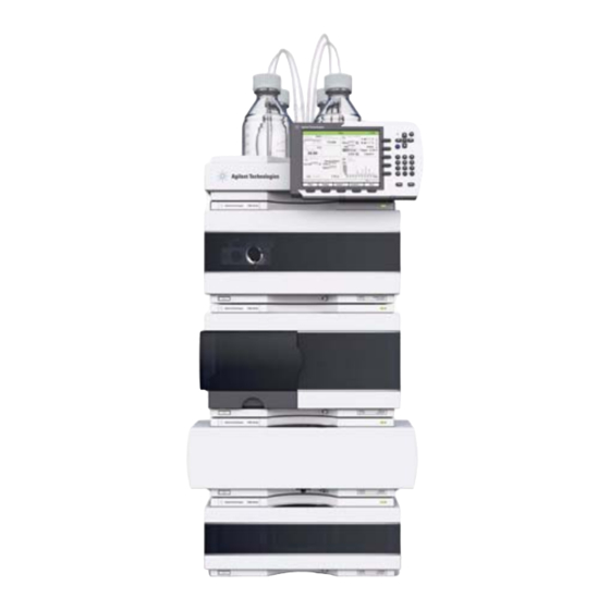
Installing the Module Optimizing the Stack Configuration Optimizing the Stack Configuration If your module is part of a complete Agilent 1260 Infinity Liquid Chromatograph, you can ensure optimum performance by installing the following configurations. These configurations optimize the system flow path, ensuring minimum delay volume. - Page 45 Installing the Module Optimizing the Stack Configuration Figure 8 Recommended Stack Configuration for 1260 (Front View) 1260 Nanoflow Pump User Manual...
- Page 46 Installing the Module Optimizing the Stack Configuration Figure 9 Recommended Stack Configuration for 1260 (Rear View) 1260 Nanoflow Pump User Manual...
-
Page 47: Two Stack Configuration
Installing the Module Optimizing the Stack Configuration Two Stack Configuration To avoid excessive height of the stack when the autosampler thermostat is added to the system it is recommended to form two stacks. Some users prefer the lower height of this arrangement even without the autosampler thermostat. - Page 48 Installing the Module Optimizing the Stack Configuration Figure 11 Recommended Two Stack Configuration for 1260 (Rear View) 1260 Nanoflow Pump User Manual...
-
Page 49: Installing The Pump
Installing the Module Installing the Pump Installing the Pump Parts required Description Pump Data System G4208A Instant Pilot Power cord For other cables see text below and “Cable Overview” on page 172. Preparations • Locate bench space. • Provide power connections. •... - Page 50 Installing the Module Installing the Pump 1 Place the module on the bench in a horizontal position. 2 Ensure the power switch at the front of the module is OFF (switch stands out). Figure 12 Front View of the Module 3 At the rear of the module move the security lever to its maximum right position.
- Page 51 Installing the Module Installing the Pump 5 Connect the required interface cables to the rear of the pump, see “Connecting Modules” on page 52. Figure 13 Rear View of the Module 6 Connect the capillary, solvent tubes and waste line (see “Flow Connections”...
-
Page 52: Connecting Modules And Control Software
Connecting Modules and Control Software Use of unsupplied cables WA R N I N G Using cables not supplied by Agilent Technologies can lead to damage of the electronic components or personal injury. ➔ Never use cables other than the ones supplied by Agilent Technologies to ensure proper functionality and compliance with safety or EMC regulations. -
Page 53: Connecting Control Software And/Or G4208 A Instant Pilot
Installing the Module Connecting Modules and Control Software Connecting Control Software and/or G4208 A Instant Pilot With the introduction of the Agilent 1260 Infinity, all GPIB interfaces have been removed. N O T E The preferred communication is LAN. Usually the detector is producing the most data in the stack, followed by the pump, and it is N O T E therefore highly recommended to use either of these modules for the LAN connection. -
Page 54: Flow Connections
Installing the Module Flow Connections Flow Connections Parts required Description Other modules G1376-68755 Accessory Kit G2226-68755 Accessory Kit (Nano Pump) wrenches 1/4 - 5/16 inch for capillary connections Preparations Pump is installed in the LC system When opening capillary or tube fittings solvents may leak out. WA R N I N G The handling of toxic and hazardous solvents and reagents can bear health risks. - Page 55 5 Using a piece of emery cloth connect the waste tubing to the EMPV and place it into your waste system. 6 If the pump is not part of an Agilent 1260 Infinity system stack or placed on the bottom of a stack, connect the corrugated waste tube to the waste outlet of the pump leak handling system.
- Page 56 Installing the Module Flow Connections 7 Purge your system before first use (see “Priming Your System With the Pump” on page 59). Figure 15 Flow connection of the nano pump 1260 Nanoflow Pump User Manual...
- Page 57 Installing the Module Flow Connections Capillary EMPV to Nano Flow sensor (4 µL flow sensor) (p/n G1375-87321) Capillary, damper to mixer (capillary pump only) (p/n 01090-87308) Capillary, filter to EMPV (p/n G1375-87400) Fused Silica/PEEK capillary 25 µm, 35 cm (p/n G1375-87322) Restriction capillary (p/n G1312-67304) Mixing capillary (p/n G1312-67302) Connecting tube, SSV to AIV (p/n G1311-67304)
-
Page 58: Get The System Ready For The First Injection
Installing the Module Get the System Ready for the First Injection Get the System Ready for the First Injection When you are using the system for the first time it is recommended to prime it to remove all the air and the possible contamination introduced in the flow path during the installation. -
Page 59: Priming Your System With The Pump
Installing the Module Get the System Ready for the First Injection 7 Repeat steps 4 to 6 for the three remaining solvent channels. 8 When all 4 channels are manually primed, remove the paper towel from the pump leak tray. Make sure that the pump leak sensor is dry before turning on the pump. - Page 60 Installing the Module Get the System Ready for the First Injection 1260 Nanoflow Pump User Manual...
-
Page 61: Using The Pump
How to Prevent and/or Reduce the Algae Problem Checkout procedure for a G2229A Nano LC System Method Parameters Test Results and Evaluation This chapter provides advice for the successful operation of the 1260 Series Nanoflow Pump and the checkout procedure for Agilent capillary HPLC-systems. Agilent Technologies... -
Page 62: Hints For Successfully Using The Pump
Using the Pump Hints For Successfully Using the Pump Hints For Successfully Using the Pump Pump Issues • Flush the pump extensively. First with in the Purge Mode, second with a pressure applied to remove all the gas bubbles. It is recommended to do this first with 100 % A and than 100 % B. - Page 63 Using the Pump Hints For Successfully Using the Pump Fused Silica Capillary Issues • When connecting a capillary (especially at the column) press it smoothly into the fitting to avoid void volumes. Incorrect setting will result in dispersion, causing tailing or footing peaks. The quartz core of PEEK/fused silica capillaries will crack and debris will clog the flow path N O T E if the fittings are overtightened.
-
Page 64: Solvent Information
Using the Pump Solvent Information Solvent Information Always filter solvents through 0.4 µm filters, small particles can permanently block the capillaries and valves. Avoid the use of the following steel-corrosive solvents: • Solutions of alkali halides and their respective acids (for example, lithium iodide, potassium chloride, and so on). -
Page 65: Algae Growth In Hplc Systems
(since the detector is the last module in the flow path, this problem is less common). Symptoms Observed with the Agilent 1260 Infinity HPLC The presence of algae in the Agilent 1260 Infinity can cause the following to occur: • Increased system pressure caused by clogging of the inline filter. Algae deposits are barely visible on the stainless steel filter frit. -
Page 66: How To Prevent And/Or Reduce The Algae Problem
Using the Pump Algae Growth in HPLC Systems • Algae growth may also be the possible source for failures of the ball valves and other components in the flow path. How to Prevent and/or Reduce the Algae Problem • Always use freshly prepared solvents, especially use demineralized water which was filtered through about 0.2 µm filters. -
Page 67: Checkout Procedure For A G2229A Nano Lc System
Using the Pump Checkout procedure for a G2229A Nano LC System Checkout procedure for a G2229A Nano LC System Use this procedure to confirm that • the system has been installed correctly • the Nanoflow LC System performs within specification •... -
Page 68: Method Parameters
Using the Pump Checkout procedure for a G2229A Nano LC System 8 Pump 0.6 µL/min, micro mode, 70 % A (water) / 30 % B (acetonitrile). Pump as long as it takes for the pressure to become stable. Pump at least 5 min more before continuing. - Page 69 Using the Pump Checkout procedure for a G2229A Nano LC System Table 17 Timetable Time 0.00 3.00 3.01 6.00 6.01 9.00 9.01 12.00 12.01 15.00 (min) Flow (µL/mi Method Parameters Micro High Performance Autosampler • Injection volume: 0.000 µL • Injection mode: Edit inj. prog. (→Inject + →Bypass) Verify that the injection valve is set to Mainpass in the Set Injection Valve box of the N O T E Autosampler Configuration dialog.
-
Page 70: Test Results And Evaluation
Using the Pump Checkout procedure for a G2229A Nano LC System Test Results and Evaluation Typical pressure in bypass mode at 600 nL/min is 100 bar and at 300 nL/min50 bar (with the Fused Silica/PEEK capillary 25 µm, 35 cm (p/n G1375-87322) installed between the flow sensor and port 1 of the injection valve plus the restriction capillary installed on port 6 of the injection valve). -
Page 71: Optimizing Performance
Hints for the Micro Vacuum Degasser Choosing the Right Pump Seals How to Choose the Primary Flow The Standard Filter How to Optimize the Compressibility Compensation Setting This chapter provides additional information about further application specific hardware and parameter optimization. Agilent Technologies... -
Page 72: Hints For The Micro Vacuum Degasser
• the pump was turned OFF for a length of time (for example over night) and volatile solvent mixtures are used. For more information see Agilent 1260 Infinity (G1379B) Micro Degasser User Manual (p/n G1379-90013). 1260 Nanoflow Pump User Manual... -
Page 73: Choosing The Right Pump Seals
Optimizing Performance Choosing the Right Pump Seals Choosing the Right Pump Seals The standard seal for the pump can be used for most applications. However applications that use normal phase solvents (for example, hexane) are not suited for the standard seal and require a different seal when used for a longer time in the pump. -
Page 74: How To Choose The Primary Flow
Optimizing Performance How to Choose the Primary Flow How to Choose the Primary Flow The primary flow can be set in three ranges: • The default range The default range is the best compromise between performance and solvent consumption. • The low solvent consumption range The low solvent consumption range, is recommended for long shallow gradient runs (e.g. -
Page 75: The Standard Filter
Optimizing Performance The Standard Filter The Standard Filter The standard filter has a volume of typically 100 µL. If the application needs a reduced volume (e.g. for fast gradient), the use of the Universal solvent filter kit, 20 µL (p/n 01090-68703) is recommended. Be aware that the filter efficiency and capacity is significantly reduced compared to the standard one. -
Page 76: How To Optimize The Compressibility Compensation Setting
Optimizing Performance How to Optimize the Compressibility Compensation Setting How to Optimize the Compressibility Compensation Setting The compressibility compensation default settings are 50 × 10 /bar (best for most aqueous solutions) for pump head A and 115 × 10 /bar (to suit organic solvents) for pump head B. - Page 77 Optimizing Performance How to Optimize the Compressibility Compensation Setting 5 Starting with a compressibility setting of 10 × 10 /bar increase the value in steps of 10. Re-zero the integrator as required. The compressibility compensation setting that generates the smallest pressure ripple is the optimum value for your solvent composition.
- Page 78 Optimizing Performance How to Optimize the Compressibility Compensation Setting 1260 Nanoflow Pump User Manual...
-
Page 79: Troubleshooting And Diagnostics
Overview of the Module’s Indicators and Test Functions Status Indicators Power Supply Indicator Module Status Indicator User Interfaces Agilent Lab Advisor Software This chapter provides information about the module's status indicators, error messages, and the available test functions in Instant Pilot and Lab Advisor. Agilent Technologies... -
Page 80: Overview Of The Module's Indicators And Test Functions
Troubleshooting and Diagnostics Overview of the Module’s Indicators and Test Functions Overview of the Module’s Indicators and Test Functions Status Indicators The module is provided with two status indicators which indicate the operational state (prerun, run, and error states) of the module. The status indicators provide a quick visual check of the operation of the module. - Page 81 Troubleshooting and Diagnostics Overview of the Module’s Indicators and Test Functions Leak Rate Test The Leak Rate Test is a diagnostic test designed to determine the pressure tightness of the pump. When a problem with the pump is suspected, use this test to help troubleshoot the pump and its pumping performance.
-
Page 82: Status Indicators
Troubleshooting and Diagnostics Status Indicators Status Indicators Two status indicators are located on the front of the module. The lower left indicates the power supply status, the upper right indicates the module status. Figure 16 Location of Status Indicators Power Supply Indicator The power supply indicator is integrated into the main power switch. -
Page 83: Module Status Indicator
Troubleshooting and Diagnostics Status Indicators Module Status Indicator The module status indicator indicates one of six possible module conditions: • When the status indicator is OFF (and power switch light is on), the module is in a prerun condition, and is ready to begin an analysis. •... -
Page 84: User Interfaces
Troubleshooting and Diagnostics User Interfaces User Interfaces Depending on the User Interface, the available tests vary. Some descriptions are only available in the Service Manual. Table 20 Test Functions available vs. User Interface Test Instant Pilot G4208A Agilent Lab Advisor software Micro Mode Pressure Test Normal Mode Pressure Test Leak Test... -
Page 85: Agilent Lab Advisor Software
Troubleshooting and Diagnostics Agilent Lab Advisor Software Agilent Lab Advisor Software The Agilent Lab Advisor software is a standalone product that can be used with or without data system. Agilent Lab Advisor software helps to manage the lab for high quality chromatographic results and can monitor in real time a single Agilent LC or all the Agilent GCs and LCs configured on the lab intranet. - Page 86 Troubleshooting and Diagnostics Agilent Lab Advisor Software 1260 Nanoflow Pump User Manual...
-
Page 87: Error Information
Pressure Above Upper Limit Pressure Below Lower Limit Pressure Signal Missing Valve Failed Missing Pressure Reading Pump Configuration Valve Fuse Inlet-Valve Fuse Temperature Out of Range Temperature Limit Exceeded Motor-Drive Power Encoder Missing Inlet-Valve Missing Electro-Magnetic-Proportional-Valve (EMPV) Missing Agilent Technologies... - Page 88 Error Information Agilent Lab Advisor Software Flow Sensor Missing Leak Sensor Missing Servo Restart Failed Pump Head Missing Index Limit Index Adjustment Index Missing Stroke Length Initialization Failed Wait Timeout Electronic fuse of SSV This chapter describes the meaning of error messages, and provides information on probable causes and suggested actions how to recover from error conditions.
-
Page 89: What Are Error Messages
Error Information What Are Error Messages What Are Error Messages Error messages are displayed in the user interface when an electronic, mechanical, or hydraulic (flow path) failure occurs which requires attention before the analysis can be continued (for example, repair, or exchange of consumables is necessary). -
Page 90: General Error Messages
Error Information General Error Messages General Error Messages General error messages are generic to all Agilent series HPLC modules and may show up on other modules as well. Timeout The timeout threshold was exceeded. Probable cause Suggested actions Check the logbook for the occurrence and The analysis was completed successfully, source of a not-ready condition. -
Page 91: Remote Timeout
Error Information General Error Messages Remote Timeout A not-ready condition is still present on the remote input. When an analysis is started, the system expects all not-ready conditions (for example, a not-ready condition during detector balance) to switch to run conditions within one minute of starting the analysis. -
Page 92: Leak Sensor Short
Error Information General Error Messages Leak Sensor Short The leak sensor in the module has failed (short circuit). The current through the leak sensor is dependent on temperature. A leak is detected when solvent cools the leak sensor, causing the leak-sensor current to change within defined limits. -
Page 93: Compensation Sensor Open
Error Information General Error Messages Compensation Sensor Open The ambient-compensation sensor (NTC) on the main board in the module has failed (open circuit). The resistance across the temperature compensation sensor (NTC) on the main board is dependent on ambient temperature. The change in resistance is used by the leak circuit to compensate for ambient temperature changes. -
Page 94: Fan Failed
Error Information General Error Messages Fan Failed The cooling fan in the module has failed. The hall sensor on the fan shaft is used by the main board to monitor the fan speed. If the fan speed falls below a certain limit for a certain length of time, the error message is generated. -
Page 95: Module Error Messages
Error Information Module Error Messages Module Error Messages Zero Solvent Counter The error message is triggered if the remaining volume in a solvent bottle falls below the set limit. Probable cause Suggested actions Refill bottles and reset solvent counters. Volume in bottle below specified volume. Make sure the set solvent volume matches the Incorrect setting. -
Page 96: Pressure Below Lower Limit
Error Information Module Error Messages Pressure Below Lower Limit The system pressure has fallen below the lower pressure limit. Probable cause Suggested actions Replenish solvent. Solvent bottle empty. Ensure the lower pressure limit is set to a value Lower pressure limit set too high. suitable for the analysis. -
Page 97: Valve Failed
Error Information Module Error Messages Valve Failed Valve 0 Failed: valve A1 Valve 1 Failed: valve A2 Valve 2 Failed: valve B2 Valve 3 Failed: valve B1 One of the solvent selection valves in the module failed to switch correctly. The processor monitors the valve voltage before and after each switching cycle. -
Page 98: Missing Pressure Reading
Error Information Module Error Messages Missing Pressure Reading The pressure readings read by the pump ADC (analog-digital converter) are missing. The ADC reads the pressure signal of from the damper every 1ms. If the readings are missing for longer than 10 seconds, the error message is generated. -
Page 99: Valve Fuse
Error Information Module Error Messages Valve Fuse Valve Fuse 0: Channels A1 and A2 Valve Fuse 1: Channels B1 and B2 One of the solvent-selection valves in the pump has drawn excessive current causing the selection-valve electronic fuse to open. Probable cause Suggested actions Restart the capillary pump. -
Page 100: Temperature Out Of Range
Error Information Module Error Messages Temperature Out of Range Temperature Out of Range 0: Pump channel A Temperature Out of Range 1: Pump channel B One of the temperature sensor readings in the motor-drive circuit are out of range. The values supplied to the ADC by the hybrid sensors must be between 0.5 V and 4.3 V. -
Page 101: Motor-Drive Power
Error Information Module Error Messages Motor-Drive Power The current drawn by the pump motor exceeded the maximum limit. Blockages in the flow path are usually detected by the pressure sensor in the damper, which result in the pump switching off when the upper pressure limit is exceeded. -
Page 102: Encoder Missing
Error Information Module Error Messages Encoder Missing The optical encoder on the pump motor in the module is missing or defective. The processor checks the presence of the pump encoder connector every 2 seconds. If the connector is not detected by the processor, the error message is generated. -
Page 103: Electro-Magnetic-Proportional-Valve (Empv) Missing
Error Information Module Error Messages Electro-Magnetic-Proportional-Valve (EMPV) Missing EMPV Missing The EMPV in the capillary pump or nanoflow pump is missing or defective. Probable cause Suggested actions Please contact your Agilent service Disconnected or defective cable. representative. Exchange the solenoid of the EMPV. Defective solenoid. -
Page 104: Servo Restart Failed
Error Information Module Error Messages Servo Restart Failed The pump motor in the module was unable to move into the correct position for restarting. When the module is switched on, the first step is to switch on the C phase of the variable reluctance motor. -
Page 105: Pump Head Missing
Error Information Module Error Messages Pump Head Missing The pump-head end stop in the pump was not found. When the pump restarts, the metering drive moves forward to the mechanical end stop. Normally, the end stop is reached within 20 seconds, indicated by an increase in motor current. -
Page 106: Index Adjustment
Error Information Module Error Messages Index Adjustment The encoder index position in the module is out of adjustment. During initialization, the first piston is moved to the mechanical stop. After reaching the mechanical stop, the piston reverses direction until the encoder index position is reached. -
Page 107: Stroke Length
Error Information Module Error Messages Stroke Length The distance between the lower piston position and the upper mechanical stop is out of limits (pump). During initialization, the module monitors the drive current. If the piston reaches the upper mechanical stop position before expected, the motor current increases as the module attempts to drive the piston beyond the mechanical stop. -
Page 108: Wait Timeout
Error Information Module Error Messages Wait Timeout When running certain tests in the diagnostics mode or other special applications, the pump must wait for the pistons to reach a specific position, or must wait for a certain pressure or flow to be reached. Each action or state must be completed within the timeout period, otherwise the error message is generated. -
Page 109: Test Functions And Calibration
Leak Test Description Running the Leak Test Evaluating the Results EMPV Test EMPV Test Description Running the EMPV Test EMPV Cleaning 1260 Nanoflow Pump EMPV Cleaning Description Running the Test This chapter describes the tests for the module. Agilent Technologies... -
Page 110: Micro Mode Pressure Test
Test Functions and Calibration Micro Mode Pressure Test Micro Mode Pressure Test Description This is a fast test to verify the tightness of a micro system, where the pump is operating in Micro Mode and no manual purge valve is installed. The flow path of the system which is tested for tightness is blocked by a blank nut. -
Page 111: Micro Mode Pressure Test Results
Test Functions and Calibration Micro Mode Pressure Test Micro Mode Pressure Test Results The test results are evaluated automatically. The sum of all leaks within the column flow path from the EMPV to the blank nut must be lower than 100 nL/min. -
Page 112: Normal Mode Pressure Test
Test Functions and Calibration Normal Mode Pressure Test Normal Mode Pressure Test Description The System Pressure Test is a quick, built-in test designed to demonstrate the pressure-tightness of the system. The test is required, if problems with small leaks are suspected, or after maintenance of flow-path components (e.g., pump seals, injection seal) to prove pressure tightness up to 400 bar. -
Page 113: Positioning The Blank Nut
Test Functions and Calibration Normal Mode Pressure Test Positioning the Blank Nut If a specific component is suspected of causing a system leak, place the blank nut immediately before the suspected component, then run the Pressure Test again. If the test passes, the defective component is located after the blank nut. Confirm the diagnosis by placing the blank nut immediately after the suspected component. -
Page 114: Running The Pressure Test
Test Functions and Calibration Normal Mode Pressure Test Running the Pressure Test When • If problems with small leaks are suspected • After maintenance of flow-path components (e.g. pump seals, injection seal) to prove pressure tightness up to 400 bar bar. Tools required Wrench 1/4 inch Parts required... -
Page 115: Evaluating The Results
Test Functions and Calibration Normal Mode Pressure Test Evaluating the Results The sum of all leaks between the pump and the blank nut will be indicated by a pressure drop of >2 bar/minute at the plateau. Note that small leaks may cause the test to fail, but solvent may not be seen leaking from a module. -
Page 116: Leak Test
Test Functions and Calibration Leak Test Leak Test Leak Test Description The Leak Test is a built-in troubleshooting test designed to demonstrate the leak-tightness of the pump. The test involves monitoring the pressure profile as the pump runs through a predefined pumping sequence. The resulting pressure profile provides information about the pressure tightness and operation of the pump components. - Page 117 Test Functions and Calibration Leak Test Plateau 2 Piston B2 delivers with a flow rate of 3 µL/min for 30 s. Ramp 5 Piston A1 delivers 50 µL/min for approximately 8 s. Plateau 3 Piston A1 delivers with a flow rate of 3 µL/min for 30 s. Ramp 6 Piston B1 delivers 50 µL/min for approximately 7 s.
-
Page 118: Running The Leak Test
Test Functions and Calibration Leak Test Running the Leak Test When If problems with the pump are suspected Tools required Wrench 1/4 inch Parts required Description G1313-87305 Restriction Capillary 01080-83202 Blank nut 500 ml Isopropanol Preparations • Place two bottles of LC-grade isopropyl alcohol in channels A2 and B2. •... -
Page 119: Evaluating The Results
Test Functions and Calibration Leak Test Evaluating the Results Defective or leaky components in the pump head lead to changes in the Leak Test pressure plot. Typical failure modes are described below. Please notice the difference between an error in the test and a failure of the test! An error N O T E means that during the operation of the test there was an abnormal termination. - Page 120 Test Functions and Calibration Leak Test Pressure limit not reached but plateaus horizontal or positive Probable cause Suggested actions Purge the degasser and pump channels Degasser and pump channels A and/or B thoroughly with isopropanol under pressure not flushed sufficiently (air in the channels). (use the restriction capillary).
- Page 121 Test Functions and Calibration Leak Test Probable cause Suggested actions Ensure all fittings are tight, or exchange Loose or leaky fittings. capillary. Tighten the mixer fittings and nuts. Leaky mixer (if installed). Ensure the pump head screws in channels A Loose pump head screws in channel A or B.
- Page 122 Test Functions and Calibration Leak Test Second plateau negative or unstable, and at least one other plateau positive Probable cause Suggested actions Clean the outlet valve in channel B. Ensure the Leaking outlet valve in channel B. sieve in the outlet valves are installed correctly. Tighten the outlet valve.
- Page 123 Test Functions and Calibration Leak Test Fourth plateau negative or unstable and at least one other plateau positive Probable cause Suggested actions Flush channel B thoroughly with isopropanol Air in pump chamber of channel B or seals under pressure (restriction capillary). not yet seated.
-
Page 124: Empv Test
Test Functions and Calibration EMPV Test EMPV Test EMPV Test Description The test is designed to verify the performance of the EMPV. The test must always be done when the EMPV valve is exchanged. The test should also be done if column flow stability problems occur (micro mode only). The EMPV test is not a substitute for the leak test or pressure test. -
Page 125: Empv Cleaning
Test Functions and Calibration EMPV Cleaning EMPV Cleaning 1260 Nanoflow Pump EMPV Cleaning Description Depending on the application, particles can sometimes collect in the EMPV. This fast cleaning routine is designed to remove such particle deposits. The routine should always be performed when the EMPV is suspected of being leaky or contaminated with particles. - Page 126 Test Functions and Calibration EMPV Cleaning 1260 Nanoflow Pump User Manual...
-
Page 127: Maintenance
Exchanging the Pump Seals and Seal Wear-in Procedure Seal Wear-in Procedure Exchanging the Pistons Exchanging the Flow Sensor Reassembling the Pump Head Assembly Exchanging the Optional Interface Board Replacing Module Firmware This chapter describes the maintenance of the module. Agilent Technologies... -
Page 128: Introduction To Maintenance
Maintenance Introduction to Maintenance Introduction to Maintenance The pump is designed for easy repair. The most frequent repairs such as piston seal exchange and filter frit replacement can be done with the pump in place in the system stack. These repairs are described in Table 23 on page 131. -
Page 129: Warnings And Cautions
Maintenance Warnings and Cautions Warnings and Cautions Toxic, flammable and hazardous solvents, samples and reagents WA R N I N G The handling of solvents, samples and reagents can hold health and safety risks. ➔ When working with these substances observe appropriate safety procedures (for example by wearing goggles, safety gloves and protective clothing) as described in the material handling and safety data sheet supplied by the vendor and follow good laboratory practice. - Page 130 Maintenance Warnings and Cautions Safety standards for external equipment C A U T I O N ➔ If you connect external equipment to the instrument, make sure that you only use accessory units tested and approved according to the safety standards appropriate for the type of external equipment.
-
Page 131: Overview Of Maintenance
Maintenance Overview of Maintenance Overview of Maintenance Table 23 Simple Repair Procedures Procedure Symptom Notes “Removing the Active Inlet Valve” If internally leaking Pressure ripple unstable, run leak test for page 138 verification “Exchanging the Outlet Valve Sieve” If internally leaking Pressure ripple unstable, run leak test for page 142 verification... - Page 132 Maintenance Overview of Maintenance Figure 17 Overview of Repair Procedures Active inlet valve, see “Removing the Active Inlet Valve” on page 138 Outlet ball valve, see “Exchanging the Outlet Valve Sieve” on page 142 Solvent selection valve, see “Exchanging the Solvent Selection Valve” on page 144 1260 Nanoflow Pump User Manual...
-
Page 133: Cleaning The Module
Maintenance Cleaning the Module Cleaning the Module The module case should be kept clean. Cleaning should be done with a soft cloth slightly dampened with water or a solution of water and mild detergent. Do not use an excessively damp cloth as liquid may drip into the module. Liquid dripping into the electronic compartment of your module. -
Page 134: Early Maintenance Feedback (Emf)
Maintenance Early Maintenance Feedback (EMF) Early Maintenance Feedback (EMF) Maintenance requires the exchange of components in the flow path which are subject to mechanical wear or stress. Ideally, the frequency at which components are exchanged should be based on the intensity of usage of the instrument and the analytical conditions, and not on a predefined time interval. -
Page 135: Using The Emf Counters
Maintenance Early Maintenance Feedback (EMF) Seal Wear Counters The Seal Wear Counters display a value derived from pressure and flow (both contribute to seal wear). The values increment with pump usage until the counters are reset after seal maintenance. Both Seal Wear Counters can be assigned an EMF (maximum) limit. -
Page 136: Checking And Cleaning The Solvent Inlet Filters
Maintenance Checking and Cleaning the Solvent Inlet Filters Checking and Cleaning the Solvent Inlet Filters When If solvent filter is blocked Parts required Description Concentrated nitric acid (65 %) Bidistilled water Beaker Preparations Remove the solvent inlet tube from the inlet port of the solvent selection valve or the adapter at the active inlet valve When opening capillary or tube fittings solvents may leak out. - Page 137 Maintenance Checking and Cleaning the Solvent Inlet Filters Cleaning the Solvent Filters 1 Remove the blocked solvent filter from the bottle-head assembly and place it in a beaker with concentrated nitric acid (35%) for one hour. 2 Thoroughly flush the filter with LC grade water (remove all nitric acid, some columns can be damaged by concentrated nitric acid).
-
Page 138: Exchanging The Active Inlet Valve Cartridge Or The Active Inlet Valve
Maintenance Exchanging the Active Inlet Valve Cartridge or the Active Inlet Valve Exchanging the Active Inlet Valve Cartridge or the Active Inlet Valve Removing the Active Inlet Valve When If defective, see next two procedures for repair details. Tools required Wrench 14 mm Parts required Description... -
Page 139: Exchanging The Valve Cartridge
Maintenance Exchanging the Active Inlet Valve Cartridge or the Active Inlet Valve Exchanging the Valve Cartridge When If internally leaking (backflow) Tools required Wrench 14 mm Parts required Description 5062-8562 Active Inlet Valve Cartridge (400 bar) 1 Using a pair of tweezers remove the valve cartridge from the actuator assembly. -
Page 140: Replacing The Active Inlet Valve Body
Maintenance Exchanging the Active Inlet Valve Cartridge or the Active Inlet Valve Replacing the Active Inlet Valve Body When • If leaking from the bottom of the active inlet valve body • If the soleniod is defective Tools required Wrench 14 mm Parts required Description G1312-60025... - Page 141 Maintenance Exchanging the Active Inlet Valve Cartridge or the Active Inlet Valve 6 After an exchange of the valve cartridge it may be required to prime the respective pump channel with several milliliters of solvent before it is completely purged and the pressure ripple has returned to its normal value. Figure 19 Exchanging the Active Inlet Valve 1260 Nanoflow Pump User Manual...
-
Page 142: Exchanging The Outlet Valve Sieve
Maintenance Exchanging the Outlet Valve Sieve Exchanging the Outlet Valve Sieve When Sieve — whenever the pump seals will be exchanged Valve — if internally leaking Tools required Wrench 1/4 inch Wrench 14 mm Parts required Description G1312-60067 Outlet valve, complete 5063-6505 Sieve (pack of 10) Before exchanging the outlet valve you can try to clean it in a sonic bath. - Page 143 Maintenance Exchanging the Outlet Valve Sieve 6 Check that the new valve is assembled correctly and that the gold seal is present (if the gold seal is deformed, it should be replaced). Figure 20 Outlet Ball Valve Parts 7 Reinstall the outlet valve and tighten the valve. 8 Reconnect the valve capillary.
-
Page 144: Exchanging The Solvent Selection Valve
Maintenance Exchanging the Solvent Selection Valve Exchanging the Solvent Selection Valve When If leaking internally, if blocked or if one of the solenoids is defective Tools required Screwdriver Pozidriv #1 Parts required Description G1312-60068 Solvent selection valve Solvent spillage C A U T I O N ➔... - Page 145 Maintenance Exchanging the Solvent Selection Valve 1 Disconnect the solvent tubes and the active inlet valve connection tubes from the solvent selection valves. Place solvent tubes into the solvent cabinet to prevent leaks due to hydrostatic flow. Figure 22 Exchanging the solvent selection valve 2 Using a Pozidriv screwdriver #1 loosen the holding screws of the valves.
-
Page 146: Removing And Disassembling The Pump Head
Maintenance Removing and Disassembling the Pump Head Removing and Disassembling the Pump Head When • Exchanging pump seals • Exchanging pistons • Exchanging seals of the seal wash option Tools required Wrench 1/4 inch 3-mm hexagonal key 4-mm hexagonal key Preparations •... - Page 147 Maintenance Removing and Disassembling the Pump Head Place the pump head on a flat surface. Loosen the lock Remove the support rings from the piston housing and lift screw (two revolutions). While holding the lower half of the housing away from the pistons. the assembly, carefully pull the pump head away from the piston housing.
-
Page 148: Exchanging The Pump Seals And Seal Wear-In Procedure
Maintenance Exchanging the Pump Seals and Seal Wear-in Procedure Exchanging the Pump Seals and Seal Wear-in Procedure When Seals leaking, if indicated by the results of the pump test (check both pump heads individually!) Tools required 3-mm hexagonal key 4-mm hexagonal key 1/4 inch wrench Parts required Description... - Page 149 Maintenance Exchanging the Pump Seals and Seal Wear-in Procedure Clean the pump chambers with lint free cloth. Ensure all Insert seals into the pump head and press firmly in particulate matter is removed. Best cleaning results will position. be achieved by removing all valves (see “Removing the Active Inlet Valve”...
-
Page 150: Seal Wear-In Procedure
Maintenance Exchanging the Pump Seals and Seal Wear-in Procedure Seal Wear-in Procedure This procedure is required for standard seals only (5063-6589), but it will definitely damage N O T E the normal phase application seals (0905-1420). 1 Place a bottle with 100 ml of Isopropanol in the solvent cabinet and place the tubing (including bottle head assembly) of the pump head that is supposed to be worn-in into the bottle. -
Page 151: Exchanging The Pistons
Maintenance Exchanging the Pistons Exchanging the Pistons When When scratched Tools required • 3-mm hexagonal key • 4-mm hexagonal key Parts required Description 5063-6586 Piston Disassemble the pump head assembly (see “Removing Check the piston surface and remove any deposits or and Disassembling the Pump Head”... - Page 152 Maintenance Exchanging the Pistons Reassemble the pump head assembly (see “Reassembling the Pump Head Assembly” on page 154). 1260 Nanoflow Pump User Manual...
-
Page 153: Exchanging The Flow Sensor
Maintenance Exchanging the Flow Sensor Exchanging the Flow Sensor When Extended flow range (100 ul) needed. Leak on the flow sensor. Unstable column flow Flow sensor blocked Tools required Screwdriver Pozidriv #1 Parts required Description G1376-60004 Nano Flow Sensor 4 µL (1260 Nanoflow Pump) 1 Turn off the pump. -
Page 154: Reassembling The Pump Head Assembly
Maintenance Reassembling the Pump Head Assembly Reassembling the Pump Head Assembly Tools required • 3-mm hexagonal key • 4-mm hexagonal key • PTFE lubricant (79846-65501) Place the support rings on the piston housing (pistons not Tighten the lock screw. installed) and snap the pump head and piston housing together. - Page 155 Maintenance Reassembling the Pump Head Assembly Carefully insert the pistons into the pump head assembly Slide the pump head assembly onto the pump drive. Apply and press them completely into the seals. a small amount of pump head grease to the pumphead screws and the balls of the spindle drive.
-
Page 156: Exchanging The Optional Interface Board
Maintenance Exchanging the Optional Interface Board Exchanging the Optional Interface Board When Board defective Parts required Description BCD (Interface) board Electronic boards are static sensitive and should be handled with care so as not to C A U T I O N damage them. -
Page 157: Replacing Module Firmware
Maintenance Replacing Module Firmware Replacing Module Firmware When The installation of newer firmware might be necessary • if a newer version solves problems of older versions or • to keep all systems on the same (validated) revision. The installation of older firmware might be necessary •... - Page 158 Maintenance Replacing Module Firmware 1260 Nanoflow Pump User Manual...
-
Page 159: Parts And Materials For Maintenance
1260 Nanoflow Pump User Manual Parts and Materials for Maintenance Pump Housing and Main Assemblies Solvent Cabinet and Bottle-Head Assembly Hydraulic Path Pump-Head Assembly Flow Sensor Assembly Nanoflow Pump Accessory Kit This chapter provides information on parts for maintenance. Agilent Technologies... -
Page 160: Pump Housing And Main Assemblies
Parts and Materials for Maintenance Pump Housing and Main Assemblies Pump Housing and Main Assemblies Repair Parts — Pump Housing and Main Assemblies (Front View) Item p/n Description G1312-60064 Pump Head without Seal Wash G1311-60001 Pump drive assembly G1311-69001 Exchange assembly for pump drive G1311-61601 Cable assembly —... - Page 161 Parts and Materials for Maintenance Pump Housing and Main Assemblies Figure 24 Overview of Main Assemblies (Front View) 1260 Nanoflow Pump User Manual...
- Page 162 Parts and Materials for Maintenance Pump Housing and Main Assemblies Repair Parts—Pump Housing and Main Assemblies (Rear View) Item p/n Description 1251-7788 Hexagonal Nut for remote/RS-232 connector 2940-0256 Nut M14 — analog output 0515-0910 Screw M4 x 0.7, 8 mm lg, to fix power supply at rear panel 0515-0924 Screw M3x0.5, 6 mm long, for Housing Front (2x) Figure 25...
-
Page 163: Solvent Cabinet And Bottle-Head Assembly
Parts and Materials for Maintenance Solvent Cabinet and Bottle-Head Assembly Solvent Cabinet and Bottle-Head Assembly Item p/n Description 5065-9981 Solvent cabinet, including all plastic parts 5042-8901 Name plate 5043-0207 Name plate 1260 5065-9954 Front panel, solvent cabinet 5042-8567 Leak pan G1311-60003 Bottle-head assembly 01018-60025... -
Page 164: Hydraulic Path
Parts and Materials for Maintenance Hydraulic Path Hydraulic Path Item p/n Description G1311-60003 Bottle-head assembly G1311-67304 Connecting tube, SSV to AIV G1312-67300 Capillary, outlet valve to piston 2 G1312-67304 Restriction capillary G1312-67302 Mixing capillary 5064-8273 Filter assembly (includes frit) 5022-2185 Replacement SS frit, 0.5 µm pore size G1375-87400 Capillary, filter to EMPV... - Page 165 Parts and Materials for Maintenance Hydraulic Path Figure 27 Hydraulic Path 1260 Nanoflow Pump User Manual...
-
Page 166: Pump-Head Assembly
Parts and Materials for Maintenance Pump-Head Assembly Pump-Head Assembly Item p/n Description G1312-60064 Pump Head without Seal Wash 5067-4695 Sapphire piston (default) G1312-60062 Adapter, integrated, 1260 G4220-63015 Support Ring without Seal Wash G4220-24013 Backup Ring for Seal Holder 5063-6589 Seal, general purpose, black, pack of 2 0905-1420 Seal, general purpose, black, pack of 2 G1312-67300... - Page 167 Parts and Materials for Maintenance Pump-Head Assembly Figure 28 Pump-Head Assembly 1260 Nanoflow Pump User Manual...
-
Page 168: Flow Sensor Assembly
Parts and Materials for Maintenance Flow Sensor Assembly Flow Sensor Assembly Description G1375-60004 NanoFlow sensor 4 µL G1375-87321 Capillary EMPV to Nano Flow sensor (4 µL flow sensor) G1375-87323 Capillary NanoFlow sensor to injection device (4 µL flow sensor), 25 µm ID, 55 cm length Figure 29 Flow Sensor Assembly... -
Page 169: Nanoflow Pump Accessory Kit
Parts and Materials for Maintenance Nanoflow Pump Accessory Kit Nanoflow Pump Accessory Kit Accessory Kit (Nano Pump) (p/n G2226-68755) Description 01018-60025 Solvent inlet filter, stainless steel (4x) 0515-0175 Mounting screw for manual purge valve holder, M4, 20 mm long 0890-1760 Tubing Flexible, 2 m 2190-0586 Washer for purge valve holder screw... - Page 170 Parts and Materials for Maintenance Nanoflow Pump Accessory Kit 1260 Nanoflow Pump User Manual...
-
Page 171: Identifying Cables
Identifying Cables Cable Overview Analog Cables Remote Cables BCD Cables CAN/LAN Cables External Contact Cable Agilent Module to PC Agilent 1200 Module to Printer This chapter provides information on cables used with the Agilent 1200 Infinity Series modules. Agilent Technologies... -
Page 172: Cable Overview
Identifying Cables Cable Overview Cable Overview Never use cables other than the ones supplied by Agilent Technologies to ensure proper N O T E functionality and compliance with safety or EMC regulations. Analog cables Description 35900-60750 Agilent module to 3394/6 integrators... - Page 173 Identifying Cables Cable Overview CAN cables Description 5181-1516 CAN cable, Agilent module to module, 0.5 m 5181-1519 CAN cable, Agilent module to module, 1 m LAN cables Description 5023-0203 Cross-over network cable, shielded, 3 m (for point to point connection) 5023-0202 Twisted pair network cable, shielded, 7 m (for point to point connection) External Contact Cable...
-
Page 174: Analog Cables
Identifying Cables Analog Cables Analog Cables One end of these cables provides a BNC connector to be connected to Agilent modules. The other end depends on the instrument to which connection is being made. Agilent Module to 3394/6 Integrators p/n 35900-60750 Pin 3394/6 Pin Agilent Signal Name... - Page 175 Identifying Cables Analog Cables Agilent Module to BNC Connector p/n 8120-1840 Pin BNC Pin Agilent Signal Name module Shield Shield Analog - Center Center Analog + Agilent Module to General Purpose p/n 01046-60105 Pin 3394/6 Pin Agilent Signal Name module Not connected Black Analog -...
-
Page 176: Remote Cables
Identifying Cables Remote Cables Remote Cables One end of these cables provides a Agilent Technologies APG (Analytical Products Group) remote connector to be connected to Agilent modules. The other end depends on the instrument to be connected to. Agilent Module to 3396A Integrators... - Page 177 Identifying Cables Remote Cables Agilent Module to 3396 Series III / 3395B Integrators p/n 03396-61010 Pin 33XX Pin Agilent Signal Name Active module (TTL) 1 - White Digital ground 2 - Brown Prepare run 3 - Gray Start 4 - Blue Shut down 5 - Pink Not connected...
- Page 178 Identifying Cables Remote Cables Agilent Module to General Purpose p/n 01046-60201 Pin Universal Pin Agilent Signal Name Active module (TTL) 1 - White Digital ground 2 - Brown Prepare run 3 - Gray Start 4 - Blue Shut down 5 - Pink Not connected 6 - Yellow Power on...
-
Page 179: Bcd Cables
Identifying Cables BCD Cables BCD Cables One end of these cables provides a 15-pin BCD connector to be connected to the Agilent modules. The other end depends on the instrument to be connected to Agilent Module to General Purpose p/n G1351-81600 Wire Color Pin Agilent Signal Name... - Page 180 Identifying Cables BCD Cables Agilent Module to 3396 Integrators p/n 03396-60560 Pin 3396 Pin Agilent Signal Name BCD Digit module BCD 5 BCD 7 BCD 6 BCD 4 BCD0 BCD 3 BCD 2 BCD 1 Digital ground + 5 V 1260 Nanoflow Pump User Manual...
-
Page 181: Can/Lan Cables
Identifying Cables CAN/LAN Cables CAN/LAN Cables Both ends of this cable provide a modular plug to be connected to Agilent modules CAN or LAN connectors. CAN Cables Description 5181-1516 CAN cable, Agilent module to module, 0.5 m 5181-1519 CAN cable, Agilent module to module, 1 m LAN Cables Description 5023-0203... -
Page 182: External Contact Cable
Identifying Cables External Contact Cable External Contact Cable One end of this cable provides a 15-pin plug to be connected to Agilent modules interface board. The other end is for general purpose. Agilent Module Interface Board to general purposes p/n G1103-61611 Color Pin Agilent Signal Name... -
Page 183: Agilent Module To Pc
Identifying Cables Agilent Module to PC Agilent Module to PC Description G1530-60600 RS-232 cable, 2 m RS232-61600 RS-232 cable, 2.5 m Instrument to PC, 9-to-9 pin (female). This cable has special pin-out, and is not compatible with connecting printers and plotters. It's also called "Null Modem Cable"... -
Page 184: Agilent 1200 Module To Printer
Identifying Cables Agilent 1200 Module to Printer Agilent 1200 Module to Printer Description 5181-1529 Cable Printer Serial & Parallel, is a SUB-D 9 pin female vs. Centronics connector on the other end (NOT FOR FW UPDATE). For use with G1323 Control Module. 1260 Nanoflow Pump User Manual... -
Page 185: Appendix
1260 Nanoflow Pump User Manual Appendix General Safety Information The Waste Electrical and Electronic Equipment Directive Batteries Information Radio Interference Sound Emission Solvent Information Agilent Technologies on Internet This chapter provides addition information on safety, legal and web. Agilent Technologies... -
Page 186: General Safety Information
Appendix General Safety Information General Safety Information The following general safety precautions must be observed during all phases of operation, service, and repair of this instrument. Failure to comply with these precautions or with specific warnings elsewhere in this manual violates safety standards of design, manufacture, and intended use of the instrument. - Page 187 Appendix General Safety Information Make sure that only fuses with the required rated current and of the specified type (normal blow, time delay, and so on) are used for replacement. The use of repaired fuses and the short-circuiting of fuse holders must be avoided. Some adjustments described in the manual, are made with power supplied to the instrument, and protective covers removed.
-
Page 188: Safety Symbols
Appendix General Safety Information Safety Symbols Table 24 Safety Symbols Symbol Description The apparatus is marked with this symbol when the user should refer to the instruction manual in order to protect risk of harm to the operator and to protect the apparatus against damage. -
Page 189: The Waste Electrical And Electronic Equipment Directive
Appendix The Waste Electrical and Electronic Equipment Directive The Waste Electrical and Electronic Equipment Directive Abstract The Waste Electrical and Electronic Equipment (WEEE) Directive (2002/96/EC), adopted by EU Commission on 13 February 2003, is introducing producer responsibility on all electric and electronic appliances starting with 13 August 2005. -
Page 190: Batteries Information
Appendix Batteries Information Batteries Information Lithium batteries may not be disposed-off into the domestic waste. Transportation of WA R N I N G discharged Lithium batteries through carriers regulated by IATA/ICAO, ADR, RID, IMDG is not allowed. Danger of explosion if battery is incorrectly replaced. ➔... -
Page 191: Radio Interference
Appendix Radio Interference Radio Interference Cables supplied by Agilent Technologies are screened to provide optimized protection against radio interference. All cables are in compliance with safety or EMC regulations. Test and Measurement If test and measurement equipment is operated with unscreened cables, or... -
Page 192: Sound Emission
Appendix Sound Emission Sound Emission Manufacturer’s Declaration This statement is provided to comply with the requirements of the German Sound Emission Directive of 18 January 1991. This product has a sound pressure emission (at the operator position) < 70 dB. •... -
Page 193: Solvent Information
Appendix Solvent Information Solvent Information Observe the following recommendations on the use of solvents. • Brown glass ware can avoid growth of algae. • Small particles can permanently block capillaries and valves. Therefore always filter solvents through 0.4 µm filters. •... -
Page 194: Agilent Technologies On Internet
Appendix Agilent Technologies on Internet Agilent Technologies on Internet For the latest information on products and services visit our worldwide web site on the Internet at: http://www.agilent.com Select Products/Chemical Analysis It will provide also the latest firmware of the modules for download. - Page 195 Index Index buffer application composition range compressibility compensation 8-bit configuration switch condensation on-board LAN configuration cable without On-Board LAN one stack analog two stack connections, flow active inlet valve 131, 138, connecting APG remote connect Agilent Diagnostic software connecting CAN vacuum degasser Agilent Lab Advisor software connecting GPIB...
- Page 196 Index EMPV test outlet valve sieve 131, outlet valve 131, EMPV cleaning index limit pistons 131, encoder missing index adjustment pump seals 131, error messages index missing purge valve frit 131, fan failed initialization failed purge valve 131, error messages inlet-valve fuse solvent selection valve compensation sensor open...
- Page 197 Index remote timeout power switch safety general information missing pressure reading pressure above upper limit standards motor-drive power pressure below lower limit symbols pressure sensor readings screwdriver pozidriv #1 pressure pulsation screwdriver pozidriv #1 144, pressure range non-operating altitude seal wear counter pressure, operating range non-operating temperature seal wear counters...
- Page 198 Index rear view wrench 1/4 inch status indicator stroke length stroke volume zero solvent counter synchronization lost system setup and installation optimizing stack configuration temperature limit exceeded temperature out of range temperature sensor test functions timeout tools screwdriver pozidriv #1 screwdriver pozidriv #1 144, wrench 1/4 inch...
- Page 200 In This Book This manual contains technical reference information about the Agilent 1260 Infinity Nanoflow Pump (G2226A). The manual describes the following: • introduction to the pump, • requirements and specifications, • installation, • using the pump, • optimizing performance, •...