Agilent Technologies 1260 Infinity User Manual
Binary pump
Hide thumbs
Also See for 1260 Infinity:
- User manual (282 pages) ,
- Service manual (108 pages) ,
- Quick start manual (98 pages)
Table of Contents
Advertisement
Quick Links
Advertisement
Chapters
Table of Contents

Related Manuals for Agilent Technologies 1260 Infinity


Summary of Contents for Agilent Technologies 1260 Infinity
- Page 1 Agilent 1260 Infinity Binary Pump User Manual Agilent Technologies...
- Page 2 1987) or any equivalent agency regulation or contract clause. Use, duplication or dis- closure of Software is subject to Agilent Technologies’ standard commercial license terms, and non-DOD Departments and Agencies of the U.S. Government will 1260 Infinity Binary Pump User Manual...
- Page 3 In This Guide... In This Guide... This manual covers the Agilent 1260 Infinity Binary Pump (G1312B). 1 Introduction to the Binary Pump This chapter gives an introduction to the module and an instrument overview. 2 Site Requirements and Specifications This chapter provides information about site requirements and specifications for the binary pump.
- Page 4 This chapter provides information on cables used with the Agilent 1200 Infinity Series modules. 13 Hardware Information This chapter provides detailed technical information about your binary pump. 14 Appendix This appendix provides general safety and environmental information. 1260 Infinity Binary Pump User Manual...
-
Page 5: Table Of Contents
Leak and Waste Handling Hints for Successful Use of the Binary Pump Setting up the Pump with the G4208A Instant Pilot Setting up the Agilent 1260 Infinity Binary Pump G1312B with the Instrument Control Interface Solvent Information Algae Growth in HPLC Systems... - Page 6 Module Error Messages 8 Test Functions and Calibration (System) Pressure Test Valve Test Binary Pump Solvent Compressibility Calibration Pump Elasticity Calibration Leak Rate Test 9 Diagnostic Signals Analog Pressure Output Diagnostic Signals in Chromatographic Data Systems 1260 Infinity Binary Pump User Manual...
- Page 7 Pump Head Assembly Without Seal Wash Pump Head Assembly with Seal Wash Option Outlet Valve Purge Valve Assembly Active Inlet Valve Assembly HPLC Starter Kit G4201-68707 HPLC Starter Kit G4202-68707 HPLC System Tool Kit Bottle Head Assembly Solvent Cabinet 1260 Infinity Binary Pump User Manual...
- Page 8 The Solvent Selection Valve (SSV) Early Maintenance Feedback Instrument Layout 14 Appendix General Safety Information The Waste Electrical and Electronic Equipment Directive Lithium Batteries Information Radio Interference Sound Emission Agilent Technologies on the Internet 1260 Infinity Binary Pump User Manual...
-
Page 9: Introduction To The Binary Pump
1260 Infinity Binary Pump User Manual Introduction to the Binary Pump Instrument and Operation Introduction to the Pump Principle of Operation Overview of the Hydraulic Path Leak and Waste Handling This chapter gives an introduction to the module and an instrument overview. -
Page 10: Instrument And Operation
(isocratic or gradient) from one of two solvents per channel. Active seal wash (optional) is available for use with concentrated buffer solutions. Outlet valve Purge valve Active inlet valve Mixer Figure 1 Overview of the binary pump 1260 Infinity Binary Pump User Manual... -
Page 11: Principle Of Operation
A purge valve with integrated PTFE frit is fitted to the pump outlet for convenient priming of the pumping system. Figure 2 The Hydraulic Path of the Binary Pump with Damper and Mixer 1260 Infinity Binary Pump User Manual... - Page 12 Instrument and Operation Damper and mixer can be bypassed for lowest delay volume of the binary pump. This configuration is recommended for low flow rate applications with steep gradients, see the Agilent 1260 Infinity Binary LC System Manual. Figure 3 on page 12 illustrates the flow path in low delay volume mode.
-
Page 13: Overview Of The Hydraulic Path
Each side of the binary pump comprises two substantially identical pump units. Both pump units comprise a ball- screw drive and a pump head with two sapphire pistons for reciprocating movement. Figure 4 Pump head 1260 Infinity Binary Pump User Manual... - Page 14 During the drawing stroke of the first piston, the second piston delivers the drawn volume into the system. For pump specifications, see “Performance Specifications” on page 26. 1260 Infinity Binary Pump User Manual...
- Page 15 Solvent compressibility calibrations acquired with a miscalibrated pump will work, but they are not transferable to other pumps. A correct pump elasticity calibration is an essential prerequisite for successful solvent compressibility calibrations. ➔ Calibrate the pump elasticity correctly. 1260 Infinity Binary Pump User Manual...
- Page 16 Unfortunately, the influence of the temperature on compressibility is non- linear and cannot be calculated. The Agilent 1260 Infinity Binary Pump features a multi point compressibility calibration. The compressibility of a solvent is determined at different pressures from 0 – 600 bar and stored in an XML file. This file can be distributed to other pumps because the solvent compressibility is independent from the pump.
- Page 17 The stroke volume for the pump is by default set to AUTO mode. This means that the stroke is optimized for the flow rate in use. A change to larger stroke volumes is possible but not recommended. 1260 Infinity Binary Pump User Manual...
-
Page 18: Leak And Waste Handling
The 1200 Infinity Series has been designed for safe leak and waste handling. It is important that all security concepts are understood and instructions are carefully followed. Figure 5 Leak and waste handling concept (overview - typical stack configuration as an example) 1260 Infinity Binary Pump User Manual... - Page 19 The waste tube of the purge valve (6) guides solvents to waste. The waste tube connected to the leak pan outlet on each of the bottom instruments (7) guides the solvent to a suitable waste container. 1260 Infinity Binary Pump User Manual...
- Page 20 Introduction to the Binary Pump Leak and Waste Handling 1260 Infinity Binary Pump User Manual...
-
Page 21: Site Requirements And Specifications
1260 Infinity Binary Pump User Manual Site Requirements and Specifications Site Requirements Physical Specifications Performance Specifications This chapter provides information about site requirements and specifications for the binary pump. Agilent Technologies... -
Page 22: Site Requirements
➔ Make sure the power connector of the instrument can be easily reached and unplugged. ➔ Provide sufficient space behind the power socket of the instrument to unplug the cable. 1260 Infinity Binary Pump User Manual... - Page 23 Never operate your instrumentation from a power outlet that has no ground connection. ➔ Never use a power cord other than the Agilent Technologies power cord designed for your region. Use of unsupplied cables WA R N I N G Using cables not supplied by Agilent Technologies can lead to damage of the electronic components or personal injury.
- Page 24 Do not store, ship or use your module under conditions where temperature fluctuations could cause condensation within the module. ➔ If your module was shipped in cold weather, leave it in its box and allow it to warm slowly to room temperature to avoid condensation. 1260 Infinity Binary Pump User Manual...
-
Page 25: Physical Specifications
Operating altitude Up to 2000 m (6562 ft) Non-operating altitude Up to 4600 m (15091 ft) For storing the module Safety standards: Installation category II, Pollution degree 2 For indoor use only. IEC, CSA, UL 1260 Infinity Binary Pump User Manual... -
Page 26: Performance Specifications
Site Requirements and Specifications Performance Specifications Performance Specifications Table 2 Performance Specifications of the Agilent 1260 Infinity Binary Pump (G1312B) Type Specification Comments Hydraulic system Two dual piston in series pumps with servo-controlled variable stroke drive, power transmission by gears and ball... - Page 27 Site Requirements and Specifications Performance Specifications Table 2 Performance Specifications of the Agilent 1260 Infinity Binary Pump (G1312B) Type Specification Comments Composition range settable range: 0 – 100 % recommended range: 1 – 99 % or 5 µL/min per channel, whatever is greater Composition <...
- Page 28 Site Requirements and Specifications Performance Specifications 1260 Infinity Binary Pump User Manual...
-
Page 29: Installing The Pump
1260 Infinity Binary Pump User Manual Installing the Pump Unpacking the Binary Pump Optimizing the Stack Configuration Installation Information on Leak and Waste Handling Installing the Binary Pump Flow Connections with Solvent Selection Valve Flow Connections without Solvent Selection Valve... -
Page 30: Unpacking The Binary Pump
Unpacking the Binary Pump Damaged Packaging If the delivery packaging shows signs of external damage, please call your Agilent Technologies sales and service office immediately. Inform your service representative that the instrument may have been damaged during shipment. "Defective on arrival" problems C A U T I O N If there are signs of damage, please do not attempt to install the module. - Page 31 For parts identification check the illustrated parts breakdown in “Parts and Materials for Maintenance” on page 183. Please report missing or damaged parts to your local Agilent Technologies sales and service office. Description G1312B Agilent 1260 Infinity Binary Pump optionally with active seal wash and/or solvent selection valve...
- Page 32 CAN cable, Agilent module to module, 1 m G1329-87300 Capillary ST 0.17 mm x 900 mm S/S pump to thermostatted autosampler G1312-87303 Capillary ST 0.17 mm x 400 mm S/S pump to injector 5042-9967 Tubing clip (set of 5 clips) 1260 Infinity Binary Pump User Manual...
-
Page 33: Optimizing The Stack Configuration
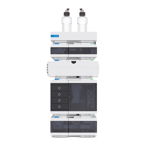
Installing the Pump Optimizing the Stack Configuration Optimizing the Stack Configuration Agilent 1260 Infinity Binary LC in Standard Delay Volume Configuration This configuration is typically used when using 4.6 mm and 3.0 mm i.d. columns. It is optimized for high flow rates and maximum sensitivity. - Page 34 Installing the Pump Optimizing the Stack Configuration Figure 6 Agilent 1260 Infinity Binary LC in standard delay volume configuration for 4.6 mm and 3.0 mm i.d. columns 1260 Infinity Binary Pump User Manual...
- Page 35 Installing the Pump Optimizing the Stack Configuration Agilent 1260 Infinity Binary LC in Medium Delay Volume Configuration This setup is used for best signal to noise ratio using 2.1 mm and 3.0 mm columns. For a more detailed help on configuring your instrument, refer to the Agilent 1260 Infinity Binary LC System User Guide.
- Page 36 Installing the Pump Optimizing the Stack Configuration Figure 8 Binary pump in medium delay volume configuration 1260 Infinity Binary Pump User Manual...
- Page 37 Installing the Pump Optimizing the Stack Configuration Agilent 1260 Infinity Binary LC in Low Delay Volume Configuration In this configuration the LC is optimized for speed with the 2.1 mm columns. For a more detailed help on configuring your instrument, refer to the Agilent 1260 Infinity Binary LC System User Guide.
- Page 38 Installing the Pump Optimizing the Stack Configuration Agilent 1260 Infinity Binary LC in Low Delay Volume Configuration with Post Column Cooler This configuration is usually used for short 2.1 mm and 3.0 mm columns optimized for high flow rates. For a more detailed help on configuring your instrument, refer to the Agilent 1260 Infinity Binary LC System User Guide.
- Page 39 Installing the Pump Optimizing the Stack Configuration Figure 10 Agilent 1260 Infinity Binary LC in low delay volume configuration for 2.1 mm and 3.0 mm id columns 1260 Infinity Binary Pump User Manual...
- Page 40 Pump Cooler f. WPS 650 mm x 0.17 mm ca. 320 mm x 0.12 mm Figure 11 Agilent 1260 Infinity Binary LC with Automated column regeneration and MS detection in low delay volume configuration 1260 Infinity Binary Pump User Manual...
-
Page 41: Installation Information On Leak And Waste Handling
A printed copy of the guideline has been shipped with the solvent cabinet, electronic copies are available on the Internet. Recommendations for Solvent Cabinet N O T E For details, see the usage guideline for the Agilent 1200 Infinity Series Solvent Cabinets. 1260 Infinity Binary Pump User Manual... - Page 42 Installing the Pump Installation Information on Leak and Waste Handling Figure 12 Leak and waste handling (overview - typical stack configuration as an example) 1260 Infinity Binary Pump User Manual...
- Page 43 ➔ Do not bend tubes. ➔ Do not immerse tube end in waste liquid. ➔ Do not intubate tubes in other tubes. ➔ For correct tubing follow instructions on label attached to the module. 1260 Infinity Binary Pump User Manual...
- Page 44 Installing the Pump Installation Information on Leak and Waste Handling Figure 13 Warning label (illustration for correct waste tubing) 1260 Infinity Binary Pump User Manual...
-
Page 45: Installing The Binary Pump
Agilent is required to evaluate if the instrument is in good condition or damaged. ➔ Notify your Agilent sales and service office about the damage. ➔ An Agilent service representative will inspect the instrument at your site and initiate appropriate actions. 1260 Infinity Binary Pump User Manual... - Page 46 2 Ensure the power switch on the front of the pump is OFF (switch stands out). Figure 14 Front of Binary Pump 3 Connect the power cable to the power connector at the rear of the module. 1260 Infinity Binary Pump User Manual...
- Page 47 7 Purge the pump (see “Initial Priming” on page 54). The pump is shipped with default configuration settings. To change these settings, refer to “Setting the 8- bit Configuration Switch (without On- board) LAN” on page 228. 1260 Infinity Binary Pump User Manual...
-
Page 48: Flow Connections With Solvent Selection Valve
1 Remove the front cover by pressing the snap fasteners on both sides. Figure 16 Removing the Front Cover 1260 Infinity Binary Pump User Manual... - Page 49 7 Hold the waste tubing with a piece of sandpaper and push it onto the purge valve outlet. Place the end into your waste system. 8 If the pump is not part of an Agilent 1260 Infinity system stack or placed on the bottom of a stack, connect the waste tube to the waste outlet of the pump leak handling system.
- Page 50 Installing the Pump Flow Connections with Solvent Selection Valve 10 Purge your system prior to the first use (see “Initial Priming” page 54). Figure 17 Binary Pump with Solvent Selection Valve 1260 Infinity Binary Pump User Manual...
-
Page 51: Flow Connections Without Solvent Selection Valve
1 Remove the front cover by pressing the snap fasteners on both sides. Figure 18 Removing the Front Cover 1260 Infinity Binary Pump User Manual... - Page 52 5 Hold the waste tubing with a piece of sandpaper and push it onto the purge valve outlet. Place the end into your waste system. 6 If the pump is not part of an Agilent 1260 Infinity system stack or placed on the bottom of a stack, connect the waste tube to the waste outlet of the pump leak handling system.
- Page 53 Installing the Pump Flow Connections without Solvent Selection Valve 8 Purge your system before first use (see “Initial Priming” on page 54). Figure 19 Flow Connection of Binary Pump without Solvent Selection Valve 1260 Infinity Binary Pump User Manual...
-
Page 54: Priming The System
The solvent at the degasser outlet will therefore not be fully degassed. Pump for approximately 10 minutes at your desired flow rate before starting an analysis. This will allow the vacuum degasser to properly degas the solvent in the degasser tubes. 1260 Infinity Binary Pump User Manual... - Page 55 6 Pump 30 mL isopropanol to remove residual air bubbles. 7 Switch to the next solvent channel and repeat steps 5 and 6 until all channels have been purged. 8 Turn the flow off and close the purge valve. 1260 Infinity Binary Pump User Manual...
-
Page 56: Regular Priming
3 Repeat step 1 and 2 for the other channel(s) of the pump. 4 Set the required composition and flow rate for your application and close the purge valve. 5 Pump for approximately 10 minutes before starting your application. 1260 Infinity Binary Pump User Manual... -
Page 57: Changing Solvents
8 Repeat steps 1 to 7 for the other channel(s) of the pump. 9 Install the desired column, set the required composition and flow rate for your application and equilibrate the system for approx. 10 minutes prior to starting a run. 1260 Infinity Binary Pump User Manual... - Page 58 After changing aqueous HPLC grade water Best solvent to re-dissolve solvents buffer crystals After the installation of normal Hexane + 5 % isopropanol Good wetting properties phase seals (PE seals (pack of 2) (0905-1420)) 1260 Infinity Binary Pump User Manual...
-
Page 59: Using The Pump
Leak and Waste Handling Hints for Successful Use of the Binary Pump Setting up the Pump with the G4208A Instant Pilot Setting up the Agilent 1260 Infinity Binary Pump G1312B with the Instrument Control Interface Overview Setup of Basic Pump Parameters... -
Page 60: Leak And Waste Handling
N O T E For details, see the usage guideline for the Agilent 1200 Infinity Series Solvent Cabinets. For details on correct installation, see “Installation Information on Leak and Waste Handling” on page 41. 1260 Infinity Binary Pump User Manual... -
Page 61: Hints For Successful Use Of The Binary Pump
• After changing the piston seals, apply the seal wear- in procedure (see “Seal Wear- in Procedure” on page 169). • Place the aqueous solvent on channel A and the organic solvent on channel B. The default compressibility settings are set accordingly. 1260 Infinity Binary Pump User Manual... -
Page 62: Setting Up The Pump With The G4208A Instant Pilot
Instant Pilot G4208A User's Guide (G4208- 90006). Details about setting up module specific parameters can be found in the Instant Pilot online help. The pump parameters are described in detail in “Overview” on page 63. 1260 Infinity Binary Pump User Manual... -
Page 63: Setting Up The Agilent 1260 Infinity Binary Pump G1312B With The Instrument Control Interface
Using the Pump Setting up the Agilent 1260 Infinity Binary Pump G1312B with the Instrument Control Interface Setting up the Agilent 1260 Infinity Binary Pump G1312B with the Instrument Control Interface Overview Parameters described in following sections is offered by the instrument control interface and can usually be accessed through Agilent instrument control software. -
Page 64: Setup Of Basic Pump Parameters
Using the Pump Setting up the Agilent 1260 Infinity Binary Pump G1312B with the Instrument Control Interface Setup of Basic Pump Parameters The most important parameters of the pump are listed in Table 4 page 64. Table 4 Basic pump parameters... -
Page 65: Pump Control
Using the Pump Setting up the Agilent 1260 Infinity Binary Pump G1312B with the Instrument Control Interface Pump Control The pump can be switched between following states: On, Off or to Standby. In Standby, the pump motor is still controlled. When the pump is switched on from standby, it does not re- initialize. -
Page 66: Auxiliary Pump Parameters
Using the Pump Setting up the Agilent 1260 Infinity Binary Pump G1312B with the Instrument Control Interface Auxiliary Pump Parameters The auxiliary pump parameters are pre- set to fit most applications. Adjustments should only be made when required. Table 5 on page 66 shows the available auxiliary parameters with their default values. -
Page 67: Data Curves
Using the Pump Setting up the Agilent 1260 Infinity Binary Pump G1312B with the Instrument Control Interface Data Curves The binary pump provides the possibility to store the following operational data in the data file of the Agilent data system: •... - Page 68 Using the Pump Setting up the Agilent 1260 Infinity Binary Pump G1312B with the Instrument Control Interface Table 6 Bottle Filling Parameters Parameter Limits Description • Total 0 – 1000 L This is the capacity (maximum possible volume) in liter of the solvent bottle. In...
-
Page 69: Solvent Information
SST, gold Pump head (body) Pistons Sapphire Piston seals/wash seals PTFE, SST (reversed phase) or UHMW-PE, SST (normal phase) Pressure sensor Purge valve SST, gold, PTFE, ceramic Damping unit SST, gold Capillaries/fittings Tubings PTFE 1260 Infinity Binary Pump User Manual... - Page 70 There is still a number of known incompatibilities with chemicals such as chloroform, methylene chloride, THF, DMSO, strong acids (nitric acid > 10 %, sulphuric acid > 10 %, sulfonic acids, trichloroacetic acid), halogenes or aequous halogene solutions, phenol and derivatives (cresols, salicylic acid etc.). 1260 Infinity Binary Pump User Manual...
- Page 71 Agilent uses UHMW (ultra- high molecular weight)- PE/PTFE blends for yellow piston and wash seals, which are used in 1290 Infinity pumps and for normal phase applications in 1260 Infinity pumps. Polyethylene has a good stability for most common inorganic solvents including acids and bases in a pH range of 1 to 12.5 .
- Page 72 It is corroded by strong bases and should not be used above pH 12 at room temperature. The corrosion of flow cell windows can negatively affect measurement results. For a pH greater than 12, the use of flow cells with sapphire windows is recommended. 1260 Infinity Binary Pump User Manual...
- Page 73 Sapphire, Ruby and Al -based ceramics Sapphire, ruby and ceramics based on aluminum oxide Al are inert to almost all common acids, bases and solvents. There are no documented incompatibilities for HPLC applications. 1260 Infinity Binary Pump User Manual...
-
Page 74: Algae Growth In Hplc Systems
• Column filters to plug giving high system pressure. • Flow cell windows of detectors to become dirty resulting in higher noise levels (since the detector is the last module in the flow path, this problem is less common). 1260 Infinity Binary Pump User Manual... -
Page 75: How To Prevent And/Or Reduce The Algae Problem
• Use the amber solvent bottle (Solvent bottle, amber (9301- 1450)) supplied with the instrument for your aqueous mobile phase. • If possible add a few mg/l sodium azide or a few percent organic solvent to the aqueous mobile phase. 1260 Infinity Binary Pump User Manual... -
Page 76: Prevent Blocking Of Solvent Filters
• Place a layer of argon on top of your solvent. • Avoid exposure of the solvent bottle to direct sunlight. Never use the system without solvent filter installed. N O T E 1260 Infinity Binary Pump User Manual... -
Page 77: Checking The Solvent Filters
• Thoroughly flush the filter with HPLC- grade water (remove all nitric acid, some capillary columns can be damaged by nitric acid). • Replace the filter. Never use the system without solvent filter installed. N O T E 1260 Infinity Binary Pump User Manual... - Page 78 Using the Pump Prevent Blocking of Solvent Filters 1260 Infinity Binary Pump User Manual...
-
Page 79: Optimizing Performance
1260 Infinity Binary Pump User Manual Optimizing Performance When to Use a Vacuum Degasser Operational Hints for the Vacuum Degasser When to Use the Active Seal Wash Option When to Use Alternative Seals When to Use the Low Volume Mixer... -
Page 80: When To Use A Vacuum Degasser
(empty) degasser if the pump does not aspirate the solvent by itself. For details see “Initial Priming” page 54. For more information see the Agilent 1260 Infinity Standard Degasser User Manual. 1260 Infinity Binary Pump User Manual... -
Page 81: When To Use The Active Seal Wash Option
The operation of the peristaltic pump can be controlled from the data system or the Instant Pilot. For adding a seal- wash option, please contact your local Agilent Technologies service representative. 1260 Infinity Binary Pump User Manual... -
Page 82: When To Use Alternative Seals
Pump Head without Seal Wash” on page 159). 2 Install normal phase seals. Polyethylene seals have a limited pressure range of 0–200 bar. When used above 200 bar, N O T E their lifetime will be significantly reduced. 1260 Infinity Binary Pump User Manual... -
Page 83: When To Use The Low Volume Mixer
When to Use the Low Volume Mixer The Low volume mixer ( 200 µL) (5067- 1565) is designed for use with the 1260 Infinity Binary LC System in low delay volume mode. This configuration is typically used for 2.1 mm i.d., 1.8 µm particle size columns, where emphasis is put on S/N ratio. -
Page 84: When To Remove Damper And Mixer
(depending on system pressure). The mixer has a volume of 400 µL. For applications that require lowest delay volume (e.g. fast gradient methods or gradient applications with low flow rates), damper and mixer can be bypassed. Figure 20 Flow Path Modifications of the Binary Pump 1260 Infinity Binary Pump User Manual... -
Page 85: Convert The Binary Pump To Low Delay Volume Mode
This paragraph shows how to bypass damper and mixer and convert the pump to low delay volume mode. Configurations where only damper or mixer are disconnected while the other part is still in line are not supported by Agilent Technologies. Tools required Description... - Page 86 Fold capillary end B away. It remains Connect fitting A to port 2 of the pressure sensor. Seal unconnected.Disconnect fitting A from outlet 1 of the port 1 of the mixer with a plastic blank nut. mixer. 1260 Infinity Binary Pump User Manual...
-
Page 87: How To Optimize The Compressibility Compensation Setting
400 bar binary pump, an average compressibility value for the solvent is sufficient. For the 600 bar 1260 Infinity Binary Pump , the pressure- dependency of a solvent compressibility needs to be considered. It is determined at different pressures between 0 –... -
Page 88: Optimization Of Legacy Compressibility Settings
10. Re- zero the integrator as required. The compressibility compensation setting that generates the smallest pressure ripple is the optimum value for your solvent composition. 6 Repeat step 1 through step 5 for the B channel of your binary pump. 1260 Infinity Binary Pump User Manual... - Page 89 How to Optimize the Compressibility Compensation Setting Table 8 Solvent Compressibility Solvent (pure) Compressibility (10 /bar) Acetone Acetonitrile Benzene Carbon tetrachloride Chloroform Cyclohexane Ethanol Ethyl acetate Heptane Hexane Isobutanol Isopropanol Methanol 1-Propanol Toluene Water 1260 Infinity Binary Pump User Manual...
- Page 90 Optimizing Performance How to Optimize the Compressibility Compensation Setting 1260 Infinity Binary Pump User Manual...
-
Page 91: Troubleshooting And Diagnostics
1260 Infinity Binary Pump User Manual Troubleshooting and Diagnostics Overview of the Module’s Indicators and Test Functions Status Indicators Power Supply Indicator Module Status Indicator User Interfaces Agilent Lab Advisor Software Overview of the troubleshooting and diagnostic features. Agilent Technologies... -
Page 92: Overview Of The Module's Indicators And Test Functions
(i.e. the high pressure flow path between pump and column). After exchanging flow path components (e.g. pump seals or injection seal), use this test to verify the system is pressure tight, see “(System) Pressure Test” on page 126. 1260 Infinity Binary Pump User Manual... - Page 93 “Leak Rate Test” on page 137. Diagnostic Signals The pump has several signals (pressure, voltages and piston movement) that can be used for diagnosing pressure stability, composition and flow problems (see chapter Diagnostic Signals). 1260 Infinity Binary Pump User Manual...
-
Page 94: Status Indicators
Figure 21 Location of Status Indicators Power Supply Indicator The power supply indicator is integrated into the main power switch. When the indicator is illuminated (green) the power is ON. 1260 Infinity Binary Pump User Manual... -
Page 95: Module Status Indicator
In such a case try to re- boot the module or try a cold- start (see “Special Settings” on page 231. Then try a firmware update (see “Replacing Module Firmware” on page 181). If this does not help, a main board replacement is required. 1260 Infinity Binary Pump User Manual... -
Page 96: User Interfaces
Depending on the user interface, the available tests vary. Some descriptions are only available in the Service Manual. Test Instant Pilot G4208A Agilent Lab Advisor Pressure Test Valve Test Solvent compressibility calibration Pump elasticity calibration 1260 Infinity Binary Pump User Manual... -
Page 97: Agilent Lab Advisor Software
For details refer to the Agilent Lab Advisor software help files. The Instrument Utilities is a basic version of the Lab Advisor with limited functionality required for installation, use and maintenance. No advanced repair, troubleshooting and monitoring functionality is included. 1260 Infinity Binary Pump User Manual... - Page 98 Troubleshooting and Diagnostics Agilent Lab Advisor Software 1260 Infinity Binary Pump User Manual...
-
Page 99: Error Information
1260 Infinity Binary Pump User Manual Error Information What Are Error Messages General Error Messages Timeout Shutdown Remote Timeout Lost CAN Partner Leak Leak Sensor Open Leak Sensor Short Compensation Sensor Open Compensation Sensor Short Fan Failed Open Cover Module Error Messages... - Page 100 Pump Head Missing Index Limit Index Adjustment Index Missing Stroke Length Initialization Failed This chapter describes the meaning of error messages, and provides information on probable causes and suggested actions how to recover from error conditions. 1260 Infinity Binary Pump User Manual...
-
Page 101: What Are Error Messages
In all cases, error propagation is done via the CAN bus or via an APG remote cable (see documentation for the APG interface). 1260 Infinity Binary Pump User Manual... -
Page 102: General Error Messages
Check the logbook for the occurrence and A not-ready condition was present during a source of a not-ready condition. Restart the sequence or multiple-injection run for a analysis where required. period longer than the timeout threshold. 1260 Infinity Binary Pump User Manual... -
Page 103: Shutdown
Check the vacuum degasser for an error The degasser failed to generate sufficient condition. Refer to the Service Manual for the vacuum for solvent degassing. degasser or the 1260 pump that has the degasser built-in. 1260 Infinity Binary Pump User Manual... -
Page 104: Remote Timeout
• Ensure all CAN cables are installed correctly. Exchange the CAN cable. Defective CAN cable. Switch off the system. Restart the system, and Defective main board in another module. determine which module or modules are not recognized by the system. 1260 Infinity Binary Pump User Manual... -
Page 105: Leak
Leak sensor not connected to the main representative. board. Please contact your Agilent service Defective leak sensor. representative. Please contact your Agilent service Leak sensor incorrectly routed, being representative. pinched by a metal component. 1260 Infinity Binary Pump User Manual... -
Page 106: Leak Sensor Short
If the resistance across the sensor increases above the upper limit, the error message is generated. Probable cause Suggested actions Please contact your Agilent service Defective main board. representative. 1260 Infinity Binary Pump User Manual... -
Page 107: Compensation Sensor Short
Fan cable disconnected. representative. Please contact your Agilent service Defective fan. representative. Please contact your Agilent service Defective main board. representative. Please contact your Agilent service Improperly positioned cables or wires representative. obstructing fan blades. 1260 Infinity Binary Pump User Manual... -
Page 108: Open Cover
Please contact your Agilent service Defective sensor or main board. representative. Ensure that the rear of module is not directly Rear of the module is exposed to strong exposed to strong sunlight. direct sunlight. 1260 Infinity Binary Pump User Manual... -
Page 109: Module Error Messages
(autosampler), seat capillary (autosampler), sample loop (autosampler), column frits and capillaries with small internal diameters (e.g. 50 µm ID). Please contact your Agilent service Defective damper. representative. Please contact your Agilent service Defective main board. representative. 1260 Infinity Binary Pump User Manual... -
Page 110: Pressure Below Lower Limit
If the pressure signal is missing, the processor detects a voltage of approximately - 120 mV across the damper connector. Probable cause Suggested actions Please contact your Agilent service Damper disconnected. representative. Please contact your Agilent service Defective damper. representative. 1260 Infinity Binary Pump User Manual... -
Page 111: Valve Failed
Solvent selection valve disconnected. representative. Please contact your Agilent service Connection cable (inside instrument) not representative. connected. Please contact your Agilent service Connection cable (inside instrument) representative. defective. Exchange the solvent selection valve. Solvent selection valve defective. 1260 Infinity Binary Pump User Manual... -
Page 112: Missing Pressure Reading
B are disconnected, and the binary pump is rebooted, the error message is generated. Probable cause Suggested actions Please contact your Agilent service Active-inlet valve and pump encoder of representative. channel B disconnected. 1260 Infinity Binary Pump User Manual... -
Page 113: Electronic Fuse Of Ssv Open
Defective active inlet valve. appears again, exchange the active inlet valve. Please contact your Agilent service Defective connection cable (front panel to representative. main board). Please contact your Agilent service Defective main board. representative. 1260 Infinity Binary Pump User Manual... -
Page 114: Temperature Out Of Range
The values supplied to the ADC by the hybrid sensors must be between 0.5 V and 4.3 V. If the values are outside this range, the error message is generated. Probable cause Suggested actions Please contact your Agilent service Defective main board. representative. 1260 Infinity Binary Pump User Manual... -
Page 115: Temperature Limit Exceeded
Ensure the outlet valve is not blocked. Partial blockage of the flowpath in front of the damper. Please contact your Agilent service Defective pump drive assembly. representative. Please contact your Agilent service Defective main board. representative. 1260 Infinity Binary Pump User Manual... -
Page 116: Motor-Drive Power
Please contact your Agilent service Defective pump drive assembly. representative. Please contact your Agilent service Defective main board. representative. Exchange restriction capillary. Restriction capillary blocked at pre-mixing union. 1260 Infinity Binary Pump User Manual... -
Page 117: Encoder Missing
Ensure the connector is seated securely. Please contact your Agilent service Disconnected or defective connection cable representative. (front panel to main board). Exchange the active inlet valve. Defective active inlet valve. 1260 Infinity Binary Pump User Manual... -
Page 118: Servo Restart Failed
Mechanical blockage of the module. is no mechanical blockage of the pump-head assembly or pump drive assembly. Please contact your Agilent service Defective pump drive assembly. representative. Please contact your Agilent service Defective main board. representative. 1260 Infinity Binary Pump User Manual... -
Page 119: Pump Head Missing
Install the pump head correctly. Ensure nothing Pump head not installed correctly (screws (e.g. capillary) is trapped between the pump not secured, or pump head not seated head and body. correctly). Exchange the piston. Broken piston. 1260 Infinity Binary Pump User Manual... -
Page 120: Index Limit
Remove the pump head, and examine the seals, Irregular or sticking drive movement. pistons, and internal components for signs of wear, contamination or damage. Exchange components as required. Please contact your Agilent service Defective pump drive assembly. representative. 1260 Infinity Binary Pump User Manual... -
Page 121: Index Adjustment
Remove the pump head, and examine the seals, Irregular or sticking drive movement. pistons, and internal components for signs of wear, contamination or damage. Exchange components as required. Please contact your Agilent service Defective pump drive assembly. representative. 1260 Infinity Binary Pump User Manual... -
Page 122: Index Missing
This current increase causes the error message to be generated. Probable cause Suggested actions Please contact your Agilent service Defective pump drive assembly. representative. 1260 Infinity Binary Pump User Manual... -
Page 123: Initialization Failed
Probable cause Suggested actions Exchange the active inlet valve. Blocked active inlet valve. Please contact your Agilent service Defective pump drive assembly. representative. Please contact your Agilent service Defective main board. representative. 1260 Infinity Binary Pump User Manual... - Page 124 Error Information Module Error Messages 1260 Infinity Binary Pump User Manual...
-
Page 125: Test Functions And Calibration
1260 Infinity Binary Pump User Manual Test Functions and Calibration (System) Pressure Test Positioning the Blank Nut Running the (System) Pressure Test Evaluating the Results Valve Test Running the Valve Test Evaluating the Results Binary Pump Solvent Compressibility Calibration Running the Solvent Compressibility Calibration... -
Page 126: (System) Pressure Test
When the system pressure reaches 600 bar, the pump continues to pump at a flow rate that keeps the pressure constant. The flow that is needed to keep the pressure constant is directly translated into a leak rate. 1260 Infinity Binary Pump User Manual... -
Page 127: Positioning The Blank Nut
(System) Pressure Test again. If the test passes, the defective component is located after the blank nut. Confirm the diagnosis by placing the blank nut immediately after the suspected component. The diagnosis is confirmed if the test fails. 1260 Infinity Binary Pump User Manual... -
Page 128: Running The (System) Pressure Test
2 Start the test and follow the instructions. Make sure to release the pressure by opening the purge valve when the test has N O T E completed. Otherwise the pump may generate an overpressure error. 1260 Infinity Binary Pump User Manual... -
Page 129: Evaluating The Results
Exclude each module one by one to determine which module is leaking. • If the pump is determined to be the source of the leak, run the valve test to identify the defective pump component. 1260 Infinity Binary Pump User Manual... - Page 130 Exchange the needle seat. Table 11 Potential Cause (Column Compartment) Potential Cause (Column Compartment) Corrective Action Loose or leaky fitting. Tighten or exchange the fitting or capillary. Rotor seal (column switching valve). Exchange the rotor seal. 1260 Infinity Binary Pump User Manual...
-
Page 131: Valve Test
The procedure from step 1 is repeated on pump head B. Step 3 The data from step 1 and 2 are evaluated. In case test failed, a conclusion about the defective part is made. 1260 Infinity Binary Pump User Manual... -
Page 132: Running The Valve Test
Make sure to release the pressure by opening the purge valve when the test has N O T E completed. Otherwise the pump may generate an overpressure error. Evaluating the Results Refer to the help file of the Agilent Lab Advisor for further details. 1260 Infinity Binary Pump User Manual... -
Page 133: Binary Pump Solvent Compressibility Calibration
The compressibility data set for this solvent is stored in an XML- file in C:\Documents and Settings\<username>\Application Data\Agilent Technologies\Agilent Lab Advisor\2.02.0.0\data\. It can be shared with other G1312B pumps via the controlling data system. 1260 Infinity Binary Pump User Manual... -
Page 134: Running The Solvent Compressibility Calibration
2 Start the test and follow the instructions. Make sure to release the pressure by opening the purge valve when the test has N O T E completed. Otherwise the pump may generate an overpressure error. 1260 Infinity Binary Pump User Manual... -
Page 135: Pump Elasticity Calibration
Solvent compressibility calibrations acquired with a miscalibrated pump will work, but they are not transferable to other pumps. A correct pump elasticity calibration is an essential prerequisite for successful solvent compressibility calibrations. ➔ Calibrate the pump elasticity correctly. 1260 Infinity Binary Pump User Manual... -
Page 136: Running The Pump Elasticity Calibration
2 Start the test and follow the instructions. Make sure to release the pressure by opening the purge valve when the test has N O T E completed. Otherwise the pump may generate an overpressure error. 1260 Infinity Binary Pump User Manual... -
Page 137: Leak Rate Test
This test does not work in emulation mode, that is when the G1312B Binary Pump emulates N O T E the G1312A Binary Pump. In case of an emulated module, convert to the original type first (see “Replacing Module Firmware” on page 181). 1260 Infinity Binary Pump User Manual... - Page 138 As soon as the flow rate of the piston exceeds the leak rate, the measured pressure will increase again. Therefore the minimum pressure of that 1260 Infinity Binary Pump User Manual...
-
Page 139: Running The Test
1 Select the Leak Rate Test from the Test Selection menu. 2 Start the test and follow the instructions. Make sure to release the pressure by slowly opening the purge valve when the test has N O T E finished. 1260 Infinity Binary Pump User Manual... -
Page 140: Evaluating The Results
Results of the leak rate test are the leak rates measured for pistons 1 and 2 as described for the test principle. If any of the leak rates exceeds 3 µL/min, the test will fail. 1260 Infinity Binary Pump User Manual... -
Page 141: Potential Causes Of Leak Rate Test Failure
2. If the second leak rate is higher than the first one, this is due to a flow back through the outlet valve. Probable cause Suggested actions Replace the part which has failed and re-run the test. Leak at outlet valve 1260 Infinity Binary Pump User Manual... - Page 142 Test Functions and Calibration Leak Rate Test 1260 Infinity Binary Pump User Manual...
-
Page 143: Diagnostic Signals
1260 Infinity Binary Pump User Manual Diagnostic Signals Analog Pressure Output Diagnostic Signals in Chromatographic Data Systems Instrument Signals This chapter explains all diagnostic signals of the binary pump. Agilent Technologies... -
Page 144: Analog Pressure Output
660 bar equals 800 mV. The signal is available in real time and can be fed into an appropriate recording device (e.g. integrator or strip chart recorder) for troubleshooting purposes. Analog pressure output Figure 22 Location of analog output connector 1260 Infinity Binary Pump User Manual... -
Page 145: Diagnostic Signals In Chromatographic Data Systems
3rd party software that supports the ICF (Instrument Control Framework) standard), the following instrument parameters are accessible during data acquisition and can be stored in the data file: • current pump pressure • solvent composition (gradient) 1260 Infinity Binary Pump User Manual... - Page 146 Diagnostic Signals Diagnostic Signals in Chromatographic Data Systems 1260 Infinity Binary Pump User Manual...
-
Page 147: Maintenance
1260 Infinity Binary Pump User Manual Maintenance Introduction to Maintenance and Repair Warnings and Cautions Cleaning the Module Overview of Maintenance and Simple Repairs Maintenance Procedures Exchanging the Purge Valve Frit or the Purge Valve Removing the Pump Head Assembly... -
Page 148: Introduction To Maintenance And Repair
These repairs are described in “Overview of Maintenance and Simple Repairs” page 152 . 1260 Infinity Binary Pump User Manual... -
Page 149: Warnings And Cautions
Agilent product user guides, or use of the products in violation of applicable laws, rules or regulations. ➔ Use your Agilent products only in the manner described in the Agilent product user guides. 1260 Infinity Binary Pump User Manual... - Page 150 A number of 1260 Infinity Binary Pumps have been shipped with pump heads labeled as 1260 Infinity pump heads and passive inlet valves. While these parts are as good from a performance perspective, they are no longer used for 1260 Infinity Binary Pumps.
-
Page 151: Cleaning The Module
WA R N I N G hazard and damage the module ➔ Do not use an excessively damp cloth during cleaning. ➔ Drain all solvent lines before opening any connections in the flow path. 1260 Infinity Binary Pump User Manual... -
Page 152: Overview Of Maintenance And Simple Repairs
“Exchanging the Active Inlet Valve (AIV) or its Cartridge” page 170 Pump head, see “Removing the Pump Head Assembly” on page 157 Solvent selection valve, see “Installation of the Solvent Selection Valve Upgrade Kit” page 175 1260 Infinity Binary Pump User Manual... -
Page 153: Maintenance Procedures
173 If internally leaking Pressure ripple unstable, run Valve Test for verification “Exchanging the Solvent Selection If internally leaking Cross port flow Valve” on page 177 If solenoid is defective Error message “Valve Failed” 1260 Infinity Binary Pump User Manual... -
Page 154: Exchanging The Purge Valve Frit Or The Purge Valve
Seal cap (OPTIONAL) Preparations • Switch off pump at the main power switch • Remove the front cover • Use an optional solvent shutoff valve or lift up solvent filters in solvent reservoirs for avoiding leakages. 1260 Infinity Binary Pump User Manual... - Page 155 2 Using the 14 mm wrench, unscrew the purge valve and remove it from the purge valve holder. 3 Remove the seal cap from the purge valve. 4 Using a pair of tweezers or a toothpick remove the frit. 1260 Infinity Binary Pump User Manual...
- Page 156 N O T E should be exchanged. 6 Insert the purge valve into the purge valve holder and orient the waste outlet nozzle downward. 7 Tighten the purge valve and reconnect outlet capillary and waste tubing. 1260 Infinity Binary Pump User Manual...
-
Page 157: Removing The Pump Head Assembly
1 Remove the front cover. 2 Disconnect the capillaries at the back of the purge valve holder, the pump head adapter and the tube at the active inlet valve. Beware of leaking solvents. 1260 Infinity Binary Pump User Manual... - Page 158 Maintenance Removing the Pump Head Assembly 3 Using a 4- mm hexagonal key stepwise loosen and remove the two pump head screws. 1260 Infinity Binary Pump User Manual...
-
Page 159: Maintenance Of A Pump Head Without Seal Wash
The following procedure describes the removal and disassembly of pump head A (left). For pump head B (right) proceed in the same way and skip steps that deal with the purge valve. 1260 Infinity Binary Pump User Manual... - Page 160 (two turns) and while holding the lower half of the the housing away from the pistons. assembly (piston housing) carefully lift up the pump housing and remove it from the piston housing. Lock screw Pump housing Piston housing 1260 Infinity Binary Pump User Manual...
- Page 161 Place a seal wash gasket in the recess of the support seals into the pump head and press them firmly in ring. Put the seal holder on top of the gasket. position. Seal holder Gasket Support ring 1260 Infinity Binary Pump User Manual...
- Page 162 If a standard seal has been installed, run the seal wear-in procedure, see “Seal Wear-in Procedure” on page 169. For the normal phase seal, the purge valve frit should be replaced, see “Exchanging the Purge Valve Frit or the Purge Valve” on page 154. 1260 Infinity Binary Pump User Manual...
-
Page 163: Maintenance Of A Pump Head With Seal Wash
The following procedure describes the removal and disassembly of pump head A (left). For pump head B (right) proceed in the same way and skip steps that deal with the purge valve. 1260 Infinity Binary Pump User Manual... - Page 164 The best way to inspect a piston is to hold it up and watch e.g. a light bulb through the piston rod. The transparent sapphire acts as a very strong magnifier and even smallest surface abnormalities become visible. 1260 Infinity Binary Pump User Manual...
- Page 165 Place a seal wash gasket in the recess of the support wash seal (spring pointing upwards) into the recess of ring. Put the seal holder on top of the gasket. the support ring. Seal holder Seal wash gasket Support ring 1260 Infinity Binary Pump User Manual...
- Page 166 Note the correct position of the pin on the support ring. Pump housing Support ring Piston housing Tighten the lock screw. Reinstall the pump head assembly, see “Reinstalling the Pump Head Assembly” on page 167. 1260 Infinity Binary Pump User Manual...
-
Page 167: Reinstalling The Pump Head Assembly
Hexagonal key, 4 mm Parts required Description 79846-65501 Pump head grease 1 Slide the pump head assembly onto the pump drive. 2 Using a 4 mm hexagonal key tighten the pump head screws stepwise with increasing torque. 1260 Infinity Binary Pump User Manual... - Page 168 Maintenance Reinstalling the Pump Head Assembly 3 Reconnect the tubing and capillaries to the connector. 1260 Infinity Binary Pump User Manual...
-
Page 169: Seal Wear-In Procedure
Reconnect the intake tubing to the solvent selection valve and the connecting tube from the solvent selection valve (if installed) to the AIV. 7 Purge your system with the solvent used for your next application. 1260 Infinity Binary Pump User Manual... -
Page 170: Exchanging The Active Inlet Valve (Aiv) Or Its Cartridge
Binary pumps without solvent selection valve (SSV) have an adapter installed between the N O T E solvent line and the active inlet valve (AIV). Disconnect the solvent tubes at the adapter and remove the adapter from the AIV. 1260 Infinity Binary Pump User Manual... - Page 171 4 Using a 14 mm wrench, loosen the active inlet valve and remove the valve from the pump head. 5 Using a pair of tweezers, remove the valve cartridge from the defective active inlet valve. 1260 Infinity Binary Pump User Manual...
- Page 172 After an exchange of the valve it may be required to pump several mL of the solvent used in N O T E the current application before the flow stabilizes at a pressure ripple as low as it used to be when the system was still working properly. 1260 Infinity Binary Pump User Manual...
-
Page 173: Exchanging The Outlet Valve
2 Unscrew the valve with the 14 mm wrench and remove it from the pump body. 3 Do not disassemble the outlet valve, as this can damage the valve. 4 Reinstall the outlet valve and tighten it using a torque wrench (12 Nm). 1260 Infinity Binary Pump User Manual... - Page 174 Maintenance Exchanging the Outlet Valve 5 Reconnect the capillary. Absorber capillary Outlet valve 1260 Infinity Binary Pump User Manual...
-
Page 175: Installation Of The Solvent Selection Valve Upgrade Kit
B1 and B2 for channel B of the right pump head. When Applicable modules: This kit is compatible to the 1260 Infinity Binary Pumps G1312B and G1312C and to the 1260 Infinity Binary Pump Clinical ed. K1312B. Tools required... - Page 176 To solvent bottles Inlets Outlets For controlling the solvent selection valve, please refer to the online help or user manual of your control software. 1260 Infinity Binary Pump User Manual...
-
Page 177: Exchanging The Solvent Selection Valve
Disconnect all tubings from the solvent selection valve. them on the table. Disconnect the solvent tubes from the solvent selection valve and empty the tubes into the bottles. Place the bottles back into the solvent cabinet. 1260 Infinity Binary Pump User Manual... - Page 178 Using a Pozidriv screwdriver #1 loosen the holding Carefully pull the valve holder out and disconnect the screws of the valve holder. valve cable at the connector. Exchange the defective solvent selection valve. Tighten the screws of the valve holder. 1260 Infinity Binary Pump User Manual...
- Page 179 After an exchange of the valve it may be required to pump several mL of solvent before the N O T E flow stabilizes at a pressure ripple as low as it used to be when the system was still working properly. 1260 Infinity Binary Pump User Manual...
-
Page 180: Exchanging The Optional Interface Board
2 Loosen the screws. Slide out the interface board from the module. BCD (interface) board Figure 24 Exchanging the Interface Board 3 Install the new interface board. Secure the screws. 4 Reconnect the cables to the board connector 1260 Infinity Binary Pump User Manual... -
Page 181: Replacing Module Firmware
1 Download the required module firmware, the latest LAN/RS- 232 FW Update Tool and the documentation from the Agilent web. • http://www.chem.agilent.com/_layouts/agilent/downloadFirmware.aspx?whid=69761 2 For loading the firmware into the module follow the instructions in the documentation. 1260 Infinity Binary Pump User Manual... - Page 182 G1312B Binary pump N O T E The module G1312B exists both as part of the 1200 Series and 1260 Infinity product lines. These modules use different solvent selection valves and main boards. Latest firmware revisions in each set automatically recognize the main board type and can be used without special handling.
-
Page 183: Parts And Materials For Maintenance
1260 Infinity Binary Pump User Manual Parts and Materials for Maintenance Hydraulic Path with Solvent Selection Valve Hydraulic Path without Solvent Selection Valve Pump Head Assembly Without Seal Wash Pump Head Assembly with Seal Wash Option Outlet Valve Purge Valve Assembly... -
Page 184: Hydraulic Path With Solvent Selection Valve
1260 Infinity Solvent selection valve (includes holder) 5041-8365 Blank plug for unused SSV channels G1312-60003 Connecting tube 1260 Infinity Solvent selection valve to active inlet valve G1312-60025 Active inlet valve body, without cartridge G1312-60045 Pump head assembly with seal wash G1312-60067... - Page 185 Parts and Materials for Maintenance Hydraulic Path with Solvent Selection Valve Figure 25 Hydraulic Path with Solvent Selection Valve 1260 Infinity Binary Pump User Manual...
-
Page 186: Hydraulic Path Without Solvent Selection Valve
Capillary ST 0.17 mm x 700 mm S/S 5062-2461 Waste tube, 5 m (reorder pack) 5042-8507 Peristaltic pump cartridge, silicone tubing 5065-9978 Tubing, 1 mm i.d., 3 mm o.d., silicone, 5 m, for seal wash option 1260 Infinity Binary Pump User Manual... - Page 187 Parts and Materials for Maintenance Hydraulic Path without Solvent Selection Valve Figure 26 Hydraulic Path without Solvent Selection Valve, with Active Seal Wash 1260 Infinity Binary Pump User Manual...
-
Page 188: Pump Head Assembly Without Seal Wash
Purge valve 1260 G1312-60067 Outlet valve 1220/1260 5042-1303 Lock screw G1312-60025 Active inlet valve body, without cartridge G1312-60020 Cartridge for active inlet valve 600 bar G1312-23201 Adapter 0515-2118 Pump head screw (M5, 60 mm) 1260 Infinity Binary Pump User Manual... - Page 189 Parts and Materials for Maintenance Pump Head Assembly Without Seal Wash Figure 27 Pump Head Assembly Without Seal Wash 1260 Infinity Binary Pump User Manual...
-
Page 190: Pump Head Assembly With Seal Wash Option
Outlet valve 1220/1260 5042-1303 Lock screw G1311-25200 Pump chamber housing G1312-60025 Active inlet valve body, without cartridge G1312-60020 Cartridge for active inlet valve 600 bar G1312-23201 Adapter 0515-2118 Pump head screw (M5, 60 mm) 1260 Infinity Binary Pump User Manual... - Page 191 Parts and Materials for Maintenance Pump Head Assembly with Seal Wash Option 16 a, b Figure 28 Pump head assembly with seal wash option 1260 Infinity Binary Pump User Manual...
-
Page 192: Outlet Valve
Parts and Materials for Maintenance Outlet Valve Outlet Valve Description G1312-60067 Outlet valve 1220/1260 Figure 29 Outlet Valve 1260 Infinity Binary Pump User Manual... -
Page 193: Purge Valve Assembly
Parts and Materials for Maintenance Purge Valve Assembly Purge Valve Assembly Item Description G1312-60061 Purge valve 1260 01018-22707 PTFE frits (pack of 5) 5067-4728 Seal cap Figure 30 Purge Valve Assembly 1260 Infinity Binary Pump User Manual... -
Page 194: Active Inlet Valve Assembly
Parts and Materials for Maintenance Active Inlet Valve Assembly Active Inlet Valve Assembly Item Description G1312-60025 Active inlet valve body, without cartridge G1312-60020 Cartridge for active inlet valve 600 bar Figure 31 Active Inlet Valve Assembly 1260 Infinity Binary Pump User Manual... -
Page 195: Hplc Starter Kit G4201-68707
Blue screw caps 100/pk 5063-6507 (2x) Chip, Column I.D. Assy 5041-2168 (2x) Solvent inlet filter, 20 µm pore size G1316-80003 Heater long-down (0.12 mm i.d., 1.6 µL internal volume) 5065-9937 Capillary/Fitting Starter Kit 0.12 mm id 1260 Infinity Binary Pump User Manual... -
Page 196: Hplc System Tool Kit
Hex key 2.5 mm, 15 cm long, straight handle 8710-2438 Hex key 2.0 mm 8710-2509 Screwdriver Torx TX8 8710-2594 Double open end wrench 4 mm 9301-0411 Syringe, Plastic 9301-1337 Adapter syringe/solvent tube with fitting 1260 Infinity Binary Pump User Manual... -
Page 197: Bottle Head Assembly
Bottle-head assembly 5063-6598 Ferrules with lock ring (10/Pk) 5063-6599 Tube screw (10/Pk) 5062-2483 Solvent tubing, 5 m 5062-8517 Inlet filter adapter (4/Pk) 5041-2168 Solvent inlet filter, 20 µm pore size Figure 32 Bottle-Head Assembly Parts 1260 Infinity Binary Pump User Manual... -
Page 198: Solvent Cabinet
Parts and Materials for Maintenance Solvent Cabinet Solvent Cabinet Figure 33 Solvent Cabinet Parts (1) Figure 34 Solvent Cabinet Parts (2) 1260 Infinity Binary Pump User Manual... - Page 199 Item Description 5065-9981 Solvent cabinet 1200 Infinity, including all plastic parts 5043-0207 Name plate 1260 5065-9954 Front panel, solvent cabinet 5042-8907 Leak panel 9301-1450 Solvent bottle, amber 9301-1420 Solvent bottle, transparent G1311-60003 Bottle-head assembly 1260 Infinity Binary Pump User Manual...
- Page 200 Parts and Materials for Maintenance Solvent Cabinet 1260 Infinity Binary Pump User Manual...
-
Page 201: Identifying Cables
1260 Infinity Binary Pump User Manual Identifying Cables Overview Analog cables Remote Cables BCD Cables CAN/LAN Cables External Contact Cables RS-232 Cable Kit Agilent 1200 Module to Printer This chapter provides information on cables used with the Agilent 1200 Infinity Series modules. -
Page 202: Overview
Identifying Cables Overview Overview Never use cables other than the ones supplied by Agilent Technologies to ensure proper N O T E functionality and compliance with safety or EMC regulations. Analog cables Description 35900-60750 Agilent module to 3394/6 integrators 35900-60750... - Page 203 It's also called "Null Modem Cable" with full handshaking where the wiring is made between pins 1-1, 2-3, 3-2, 4-6, 5-5, 6-4, 7-8, 8-7, 9-9. 5181-1561 RS-232 cable, 8 m 1260 Infinity Binary Pump User Manual...
-
Page 204: Analog Cables
Pin Agilent Signal Name module Not connected Shield Analog - Center Analog + Agilent Module to BNC Connector p/n 8120-1840 Pin BNC Pin Agilent Signal Name module Shield Shield Analog - Center Center Analog + 1260 Infinity Binary Pump User Manual... - Page 205 Identifying Cables Analog cables Agilent Module to General Purpose p/n 01046-60105 Pin Agilent Signal Name module Not connected Black Analog - Analog + 1260 Infinity Binary Pump User Manual...
-
Page 206: Remote Cables
Identifying Cables Remote Cables Remote Cables One end of these cables provides a Agilent Technologies APG (Analytical Products Group) remote connector to be connected to Agilent modules. The other end depends on the instrument to be connected to. Agilent Module to 3396A Integrators... - Page 207 Not connected 6 - Yellow 6 - Yellow Power on High 7 - Red 7 - Red Ready High 8 - Green 8 - Green Stop 9 - Black 9 - Black Start request 1260 Infinity Binary Pump User Manual...
- Page 208 01046-60201 Wire Color Pin Agilent Signal Name Active module (TTL) White Digital ground Brown Prepare run Gray Start Blue Shut down Pink connected Yellow Power on High Ready High Green Stop Black Start request 1260 Infinity Binary Pump User Manual...
-
Page 209: Bcd Cables
Black BCD 0 Orange BCD 3 BCD 2 Brown BCD 1 Gray Digital ground Gray Gray/pink BCD 11 Red/blue BCD 10 White/green BCD 9 Brown/green BCD 8 not connected not connected + 5 V 1260 Infinity Binary Pump User Manual... - Page 210 Agilent Module to 3396 Integrators p/n 03396-60560 Pin 3396 Pin Agilent Signal Name BCD Digit module BCD 5 BCD 7 BCD 6 BCD 4 BCD0 BCD 3 BCD 2 BCD 1 Digital ground + 5 V 1260 Infinity Binary Pump User Manual...
-
Page 211: Can/Lan Cables
CAN cable, Agilent module to module, 1 m LAN Cables Description 5023-0203 Cross-over network cable, shielded, 3 m (for point to point connection) 5023-0202 Twisted pair network cable, shielded, 7 m (for point to point connection) 1260 Infinity Binary Pump User Manual... -
Page 212: External Contact Cables
EXT 2 Grey EXT 3 Pink EXT 3 Blue EXT 4 EXT 4 Black Not connected Violet Not connected Grey/pink Not connected Red/blue Not connected White/green Not connected Brown/green Not connected White/yellow Not connected 1260 Infinity Binary Pump User Manual... -
Page 213: Rs-232 Cable Kit
It's also called "Null Modem Cable" with full handshaking where the wiring is made between pins 1-1, 2-3, 3-2, 4-6, 5-5, 6-4, 7-8, 8-7, 9-9. 5181-1561 RS-232 cable, 8 m 1260 Infinity Binary Pump User Manual... -
Page 214: Agilent 1200 Module To Printer
Agilent 1200 Module to Printer Description 5181-1529 Cable Printer Serial & Parallel, is a SUB-D 9 pin female vs. Centronics connector on the other end (NOT FOR FW UPDATE). For use with G1323 Control Module. 1260 Infinity Binary Pump User Manual... -
Page 215: Hardware Information
1260 Infinity Binary Pump User Manual Hardware Information Firmware Description Electrical Connections Rear view of the module Interfaces Overview Interfaces Setting the 8-bit Configuration Switch (without On-board) LAN Communication Settings for RS-232C Special Settings Optional Interface Boards The Solvent Selection Valve (SSV) -
Page 216: Firmware Description
• run synchronization through APG remote, • error handling, • diagnostic functions, • or module specific functions like • internal events such as lamp control, filter movements, • raw data collection and conversion to absorbance. 1260 Infinity Binary Pump User Manual... - Page 217 Update of main system can be done in the resident system only. Update of the resident N O T E system can be done in the main system only. Main and resident firmware must be from the same set. Figure 35 Firmware Update Mechanism 1260 Infinity Binary Pump User Manual...
- Page 218 All these specific informations are described in the documentation provided with the firmware update tools. The firmware update tools, firmware and documentation are available from the Agilent web. • http://www.chem.agilent.com/_layouts/agilent/downloadFirmware.aspx?whid=69761 1260 Infinity Binary Pump User Manual...
-
Page 219: Electrical Connections
There are no externally accessible fuses, because automatic electronic fuses are implemented in the power supply. Never use cables other than the ones supplied by Agilent Technologies to ensure proper N O T E functionality and compliance with safety or EMC regulations. -
Page 220: Rear View Of The Module
Hardware Information Electrical Connections Rear view of the module Configuration switch Slot for interface board RS232 Remote Analog output CAN-Bus HP-IB Power plug Figure 36 Electrical connections to the binary pump 1260 Infinity Binary Pump User Manual... -
Page 221: Interfaces
G1364C FC-AS G1330B/K1330B μ CAN-DC- OUT for CAN G1364D FC- slaves G1367E HiP ALS K1367E HiP ALS Clinical Ed. G1377A HiP micro ALS G2258A DL ALS G5664A Bio-inert FC-AS G5667A Bio-inert Autosampler G4226A ALS 1260 Infinity Binary Pump User Manual... - Page 222 K1321B FLD Clinical Ed. G1321C FLD G1362A RID G4280A ELSD EXT Contact AUTOZERO Others G1170A Valve Drive G1316A/C TCC K1316C TCC Clinical Ed. G1322A DEG K1322A DEG Clinical Ed. G1379B DEG G4225A DEG K4225A DEG Clinical Ed. 1260 Infinity Binary Pump User Manual...
- Page 223 • CAN connectors as interface to other modules • LAN connector as interface to the control software • RS- 232C as interface to a computer • REMOTE connector as interface to other Agilent products • Analog output connector(s) for signal output 1260 Infinity Binary Pump User Manual...
-
Page 224: Overview Interfaces
There is no configuration possible on main boards with on-board LAN. These are N O T E pre-configured for • 19200 baud, • 8 data bit with no parity and • one start bit and one stop bit are always used (not selectable). 1260 Infinity Binary Pump User Manual... - Page 225 RS-232C Connection Table Direction Function Ground Figure 37 RS-232 Cable Analog Signal Output The analog signal output can be distributed to a recording device. For details refer to the description of the module’s main board. 1260 Infinity Binary Pump User Manual...
- Page 226 APG Remote The APG Remote connector may be used in combination with other analytical instruments from Agilent Technologies if you want to use features as common shut down, prepare, and so on. Remote control allows easy connection between single instruments or systems to ensure coordinated analysis with simple coupling requirements.
- Page 227 START REQUEST (L) Request to start injection cycle (for example, by start key on any module). Receiver is the autosampler. Special Interfaces There is no special interface for this module. 1260 Infinity Binary Pump User Manual...
-
Page 228: Setting The 8-Bit Configuration Switch (Without On-Board) Lan
N O T E Switch settings provide configuration parameters for serial communication protocol and instrument specific initialization procedures. With the introduction of the Agilent 1260 Infinity, all GPIB interfaces have been removed. N O T E The preferred communication is LAN. -
Page 229: Communication Settings For Rs-232C
Use the following tables for selecting the setting which you want to use for RS- 232C communication. The number 0 means that the switch is down and 1 means that the switch is up. 1260 Infinity Binary Pump User Manual... - Page 230 Parity No Parity Odd Parity Even Parity One start bit and one stop bit are always used (not selectable). Per default, the module will turn into 19200 baud, 8 data bit with no parity. 1260 Infinity Binary Pump User Manual...
-
Page 231: Special Settings
Save your methods and data before executing a forced cold start. If you use the following switch settings and power the instrument up again, a forced cold start has been completed. Table 23 Forced Cold Start Settings (without on-board LAN) Mode Select TEST/BOOT 1260 Infinity Binary Pump User Manual... -
Page 232: Optional Interface Boards
The BCD board provides a BCD output for the bottle number of the Agilent 1200 Series autosampler and four external contacts. The external contact closure contacts are relay contacts. The maximum settings are: 30 V (AC/DC); 250 mA (fused). 1260 Infinity Binary Pump User Manual... - Page 233 Detailed connector layout (1200) Signal name BCD digit BCD 5 BCD 7 BCD 6 BCD 4 BCD 0 BCD 3 BCD 2 BCD 1 Digital ground BCD 11 BCD 10 BCD 9 BCD 8 1260 Infinity Binary Pump User Manual...
- Page 234 G1369C or Interface board (LAN) G1369-60012 One board is required per Agilent 1260 Infinity instrument. It is recommended to add the N O T E LAN board to the detector with highest data rate. For the configuration of the G1369 LAN Communication Interface card refer to its N O T E documentation.
- Page 235 Hardware Information Optional Interface Boards The following cards can be used with the Agilent 1260 Infinity modules. Table 25 LAN Boards Type Vendor Supported networks Interface board (LAN) (G1369B Agilent Technologies Fast Ethernet, Ethernet/802.3, or G1369-60002) or RJ-45 (10/100Base-TX) Interface board (LAN) (G1369C...
-
Page 236: The Solvent Selection Valve (Ssv)
(here: B) and using always the same solvent for channel A. Technically, the 1260 Infinity SSV uses two electromagnetic valves. If the current is off, inlets A2 and B2 are connected to the outlet. If the current is on, the valves switch to A1 and/or B1. -
Page 237: Early Maintenance Feedback
EMF limits, and then reset the EMF counters to zero. The next time the EMF counters exceed the new EMF limits, the EMF flag will be displayed, providing a reminder that maintenance needs to be scheduled. 1260 Infinity Binary Pump User Manual... -
Page 238: Instrument Layout
• the plastic layers help cushion the electronic and mechanical parts from physical shock, and • the metal inner cabinet shields the internal electronics from electromagnetic interference and also helps to reduce or eliminate radio frequency emissions from the instrument itself. 1260 Infinity Binary Pump User Manual... -
Page 239: Appendix
1260 Infinity Binary Pump User Manual Appendix General Safety Information The Waste Electrical and Electronic Equipment Directive Lithium Batteries Information Radio Interference Sound Emission Agilent Technologies on the Internet This appendix provides general safety and environmental information. Agilent Technologies... -
Page 240: General Safety Information
C A U T I O N alerts you to situations that could cause loss of data, or damage of equipment. ➔ Do not proceed beyond a caution until you have fully understood and met the indicated conditions. 1260 Infinity Binary Pump User Manual... - Page 241 Agilent Technologies assumes no liability for the customer’s failure to comply with these requirements. Ensure the proper usage of the equipment.
- Page 242 When working with solvents, observe appropriate safety procedures (for example, goggles, safety gloves and protective clothing) as described in the material handling and safety data sheet by the solvent vendor, especially when toxic or hazardous solvents are used. 1260 Infinity Binary Pump User Manual...
-
Page 243: The Waste Electrical And Electronic Equipment Directive
Monitoring and Control Instrumentation product. Do not dispose off in domestic household waste N O T E To return unwanted products, contact your local Agilent office, or see www.agilent.com more information. 1260 Infinity Binary Pump User Manual... -
Page 244: Lithium Batteries Information
Ved udskiftning benyttes kun batteri som anbefalt av apparatfabrikanten. ➔ Brukt batteri returneres appararleverandoren. Bij dit apparaat zijn batterijen geleverd. Wanneer deze leeg zijn, moet u ze niet weggooien N O T E maar inleveren als KCA. 1260 Infinity Binary Pump User Manual... -
Page 245: Radio Interference
Appendix Radio Interference Radio Interference Cables supplied by Agilent Technologies are screened to provide optimized protection against radio interference. All cables are in compliance with safety or EMC regulations. Test and Measurement If test and measurement equipment is operated with unscreened cables, or... -
Page 246: Sound Emission
This product has a sound pressure emission (at the operator position) < 70 dB. • Sound Pressure Lp < 70 dB (A) • At Operator Position • Normal Operation • According to ISO 7779:1988/EN 27779/1991 (Type Test) 1260 Infinity Binary Pump User Manual... -
Page 247: Agilent Technologies On The Internet
Appendix Agilent Technologies on the Internet Agilent Technologies on the Internet For the latest information on products and services visit our worldwide web site on the Internet at: http://www.agilent.com 1260 Infinity Binary Pump User Manual... - Page 248 AUTO mode defect on arrival external contact delay volume overview delivery checklist ball-screw drive remote design battery RS-232 diagnostic signals safety information dimensions BCD board cable dual-piston in-series design 1260 Infinity Binary Pump User Manual...
- Page 249 1260 Infinity Binary Pump User Manual...
- Page 250 132, non-operating altitude pressure ripple ripple non-operating temperature pressure signal missing composition pressure test pressure results RS-232C operating Altitude pressure cable operating temperature operating range communication settings 1260 Infinity Binary Pump User Manual...
- Page 251 10, 48, 153, timeout troubleshooting solvent zero counter error messages solvents, change status indicators sound emission 1260 Infinity Binary Pump User Manual...
- Page 252 In This Book This manual contains technical reference information about the Agilent 1260 Infinity Binary Pump G1312B. The manual describes the following: • introduction, • site requirements and specifications, • installing the pump, • using the binary pump, • optimizing performance, •...