Agilent Technologies 1260 Infinity User Manual
Hide thumbs
Also See for 1260 Infinity:
- User manual (282 pages) ,
- Service manual (108 pages) ,
- Quick start manual (98 pages)

Related Manuals for Agilent Technologies 1260 Infinity


Summary of Contents for Agilent Technologies 1260 Infinity
- Page 1 Agilent 1260 Infinity Multi-Detector Suite User Manual Agilent MDS User Manual Agilent Technologies...
- Page 2 Notices Warranty © Agilent Technologies, Inc. 2014 receive no greater than Restricted Rights as defined in FAR 52.227-19(c)(1-2) (June No part of this manual may be reproduced The material contained in this docu- 1987). U.S. Government users will receive in any form or by any means (including elec- ment is provided “as is,”...
- Page 3 In this book... This manual contains information on: • Agilent 1260 Infinity GPC/SEC MDS (G7800A) • Agilent 1260 Infinity Bio- SEC MDS (G7805A) 1 Introduction to the 1260 Infinity MDS This chapter gives an instrument overview and an introduction to the function of the MDS detectors.
- Page 4 9 Maintenance This chapter describes the maintenance of the 1260 Infinity Mulit- Detector Suite. 10 Parts and Materials for Maintenance This chapter provides information on parts for maintenance.
-
Page 5: Table Of Contents
Introduction Instrument Overview The 1260 Infinity MDS Refractive Index Detector The 1260 Infinity MDS Viscometer The 1260 Infinity MDS Dual Angle Light Scattering Detector The 1260 Infinity MDS Dynamic Light Scattering Detector 2 Site Requirements and Specifications Pre-installation Requirements Site Requirements... - Page 6 Contents 6 Optimizing Performance Location of the 1260 Infinity MDS Routine Maintenance of the MDS System Purging the Detectors Optimizing RI Performance Optimizing Viscometer Performance Optimizing Light Scattering Performance Shutting-down the Instrument 7 Troubleshooting and Diagnostics Troubleshooting Troubleshooting an LC System...
- Page 7 Contents 11 Appendix 1– Theory of Operation The 1260 Infinity MDS Refractive Index Detector The 1260 Infinity MDS Viscometer The 1260 Infinity MDS Light-Scattering Detector 12 Appendix 2 – General Safety Information General Safety Information The Waste Electrical and Electronic Equipment Directive...
- Page 8 Contents Agilent MDS User Manual...
-
Page 9: Introduction To The 1260 Infinity Mds
The 1260 Infinity MDS Refractive Index Detector The 1260 Infinity MDS Viscometer The 1260 Infinity MDS Dual Angle Light Scattering Detector The 1260 Infinity MDS Dynamic Light Scattering Detector This chapter gives an instrument overview and an introduction to the function of the MDS detectors. -
Page 10: Introduction
Introduction to the 1260 Infinity MDS Introduction Introduction The Agilent 1260 Infinity Multi- Detector Suite (MDS) is a high- end multiple detector platform, which provides not only accurate molecular weight data independent of the chemistry of the standards, but also gives insight into the behavior of the polymer in solution. - Page 11 Introduction to the 1260 Infinity MDS Introduction With state of the art detector design and control interfaces built around ease of use, the 1260 Infinity MDS is the solution to expanding GPC/SEC beyond conventional limits. “Performance Specifications” on page 34 gives an overview of the system’s performance specifications.
-
Page 12: Instrument Overview
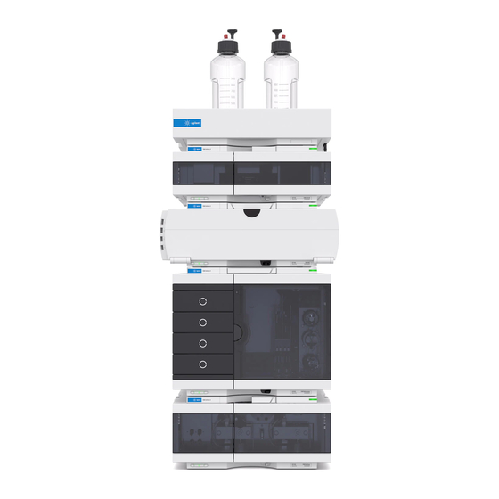
Instrument Overview Instrument Overview Basic Principles of Operation The 1260 Infinity MDS is designed to complement existing liquid chromatography systems to allow them to be used for GPC/SEC, configured with dual or quad detector cabinets depending on the detector choice, see Figure 1 on page 12. - Page 13 Introduction to the 1260 Infinity MDS Instrument Overview MDS Control Unit The MDS is controlled using the MDS Control Unit, which is fixed on top of the detector enclosure(s). The control unit remains identical regardless of the configuration of detectors in the system, allowing easy upgrading of additional detectors.
- Page 14 Each door provides a storage area: the top door for manuals, and the bottom door for holding spanners. Upgrading the 1260 Infinity MDS with additional detectors is simple. Tidy draws are swapped out for detectors and if a triple system is required a bottom enclosure is added.
- Page 15 Auxiliary I/O Port. The port may be connected to the LC system operating with the 1260 Infinity MDS to shut down the pump and minimize solvent spillage. The keypad is locked on receiving a sample injection trigger via the Auxiliary I/O port or from a Start Collection command from the Agilent GPC/SEC Software, if used.
- Page 16 Introduction to the 1260 Infinity MDS Instrument Overview G7800A – Agilent 1260 Infinity GPC/SEC MDS Conventional GPC The simplest offering is the MDS fitted with a refractive index (RI) detector. This system can be used to collect ‘conventional’ GPC data to allow molecular weight analysis via the use of a column calibration in the traditional GPC experiment.
- Page 17 Instrument Overview G7805A– Agilent 1260 Infinity Bio-SEC MDS For the 1260 Infinity Bio- SEC MDS, Agilent Technologies uses highest- quality materials in the flow path (also referred to as wetted parts), which are widely accepted by life scientists, as they are known for optimum inertness to biological samples.
- Page 18 Instrument Overview Data Collection and Analysis The 1260 Infinity MDS provides on- board digital data acquisition, allowing data to be collected from the built- in detectors directly into Agilent Software via the USB port at the rear of the control unit. The data is collected at 24 bit resolution with collecting rates of 1, 2, 5 and 10 Hz selectable within the software.
-
Page 19: The 1260 Infinity Mds Refractive Index Detector
Introduction to the 1260 Infinity MDS The 1260 Infinity MDS Refractive Index Detector The 1260 Infinity MDS Refractive Index Detector The MDS differential refractive index detector is a high performance device that is specifically designed for GPC. The RI detector features high signal- to- noise and low levels of drift and is fitted with a low dispersion cell to maintain peak shapes throughout the sample injection. - Page 20 Introduction to the 1260 Infinity MDS The 1260 Infinity MDS Refractive Index Detector Before running solvent through the device, make sure that the solvent within the detector is completely miscible with the intended solvent to be used. In case of immiscible solvents, the cell must be rinsed through with an intermediate solvent (for example acetone), which is miscible with both solvents.
-
Page 21: The 1260 Infinity Mds Viscometer
Introduction to the 1260 Infinity MDS The 1260 Infinity MDS Viscometer The 1260 Infinity MDS Viscometer The MDS Viscometer is a temperature- controlled four- capillary fused silica bridge viscometer that is capable of measuring solution- based viscosities for a wide range of polymer samples and molecular weights. The balanced... - Page 22 Introduction to the 1260 Infinity MDS The 1260 Infinity MDS Viscometer Figure 4 Flow path of MDS Viscometer during purge Red lines – flowing path Black lines – immobilized mobile path The T-connection results in both sides of the flow cell always being exposed to the same...
- Page 23 Introduction to the 1260 Infinity MDS The 1260 Infinity MDS Viscometer Figure 5 Flow path of MDS Viscometer during DP purge Red lines – flowing path Black lines – immobilized mobile path The T-connection results in both sides of the flow cell always being exposed to the same...
-
Page 24: The 1260 Infinity Mds Dual Angle Light Scattering Detector
Introduction to the 1260 Infinity MDS The 1260 Infinity MDS Dual Angle Light Scattering Detector The 1260 Infinity MDS Dual Angle Light Scattering Detector The MDS LS detector is a Dual Angle (15 ° / 90 °) Light Scattering Detector, which is capable of measuring the molecular weight and molecular dimensions of polymer molecules in solution without the need for a column calibration. -
Page 25: The 1260 Infinity Mds Dynamic Light Scattering Detector
Introduction to the 1260 Infinity MDS The 1260 Infinity MDS Dynamic Light Scattering Detector The 1260 Infinity MDS Dynamic Light Scattering Detector The MDS DLS detector is a 90 ° Light Scattering Detector, with a further Dynamic Light Scattering detector on the same sample cell. This allows all the same functionality as the Dual Angle Light Scattering Detector but with hydrodynamic size measurements, without increasing dead- volume. - Page 26 Introduction to the 1260 Infinity MDS The 1260 Infinity MDS Dynamic Light Scattering Detector Agilent MDS User Manual...
-
Page 27: Site Requirements And Specifications
Agilent MDS User Manual Site Requirements and Specifications Pre-installation Requirements Site Requirements Physical Specifications Performance Specifications This chapter provides information on environmental requirements, physical and performance specifications. Agilent Technologies... -
Page 28: Pre-Installation Requirements
Site Requirements and Specifications Pre-installation Requirements Pre-installation Requirements The MDS operation manual describes the environmental and operating requirements of the instrument. You must prepare your laboratory according to these instructions before the system can be installed. If you have misplaced your copy, you can obtain a replacement from your local Agilent office. -
Page 29: Site Requirements
Site Preparation Checklist for more details. Laser Safety When the Agilent LSD or LS/DLS detector is installed, the 1260 Infinity MDS is classified as a "Laser Class 1" product (IEC825- 1, CFR1040.10 & 1040.11). During normal operation of the Agilent 1260 Infinity MDS no laser light is accessible to the user. - Page 30 Never operate your instrumentation from a power outlet that has no ground connection. ➔ Never use a power cord other than the Agilent Technologies power cord designed for your region. Use of unsupplied cables WA R N I N G Using cables not supplied by Agilent Technologies can lead to damage of the electronic components or personal injury.
- Page 31 Site Requirements and Specifications Site Requirements Bench Space The module dimensions and weight (see Table 2 on page 33) allow you to place the module on almost any desk or laboratory bench. It needs an additional 2.5 cm (1.0 inches) of space on either side and approximately 8 cm (3.1 inches) in the rear for air circulation and electric connections.
- Page 32 Site Requirements and Specifications Site Requirements Extraction Requirement The MDS is not fitted with extraction, but depending on the solvents used it might be necessary to site the unit under an extraction hood or installed in a fume cupboard. Temperature stability impaired C A U T I O N Locating the unit in a fume cupboard may compromise the temperature stability of the detector(s).
-
Page 33: Physical Specifications
Site Requirements and Specifications Physical Specifications Physical Specifications Table 2 Physical Specifications Type Specification Comments Weight 10 kg (Dual compartment), 20 kg (Quad Compartment) Dimensions (height × 400 x 490 x 390 mm Dual compartment width × depth) (15.8 x 19.2 x 15.4 inches), 400 x 490 x 650 mm Quad compartment (15.8 x 19.2 x 25.6 inches) -
Page 34: Performance Specifications
Site Requirements and Specifications Performance Specifications Performance Specifications Table 3 Optional Refractive Index Detector Performance Specifications Type Specification Detection type Deflection Wavelength 658 nm Short-term noise <80 µV Cell volume 6 µL Pressure rating 350 kPa (50 psi) Wetted materials 316 SST, Quartz Temperature range 30 –... - Page 35 Site Requirements and Specifications Performance Specifications Table 5 Optional Dual Angle LS Detectors Performance Specifications Type Specification Sample cell volume 10 µL Scattering volume 0.01 µL Laser wavelength 658 nm Scattering angles 15 ° and 90 ° Temperature range 30 – 60 °C Temperature stability ±...
- Page 36 Site Requirements and Specifications Performance Specifications Agilent MDS User Manual...
-
Page 37: Installation
Single Detector System Dual Detector System Triple Detector System Other Connections USB Port Analog Outputs Analog Inputs Auxiliary I/O Port Serial RS232 Port Service Port and Switch This chapter gives information about the installation of your MDS instrument. Agilent Technologies... -
Page 38: Unpacking The Module
Delivery Checklist Unpack the 1260 Infinity MDS and accessories, and ensure that all parts and materials shown in the table below have been delivered with your module. Report any missing or damaged parts to your local Agilent Technologies sales and service office. - Page 39 1260 Infinity GPC/SEC MDS 1200 Accessory Kit (OPTIONAL) G7800-68002 Universal Accessory Kit (OPTIONAL) Optional Detectors: Description G7801A Agilent 1260 Infinity GPC/SEC MDS RI Detector G7802A Agilent 1260 Infinity GPC/SEC MDS Viscometer G7803A Agilent 1260 Infinity GPC/SEC GPC MDS Dual Angle LSD Agilent MDS User Manual...
- Page 40 1260 Infinity Bio-SEC MDS Dual Compartment Power cord G7800-68000 Agilent 1260 Infinity MDS Installation Kit G7800-63000 Drawer Unit (OPTIONAL) G7800-68001 1260 Infinity GPC/SEC MDS 1200 Accessory Kit (OPTIONAL) G7800-68002 Universal Accessory Kit (OPTIONAL) Optional Detectors: Description G7808A Agilent 1260 Infinity Bio-SEC LSD...
- Page 41 Installation Unpacking the Module Installation Kit Agilent 1260 Infinity MDS Installation Kit (G7800- 68000) contains the following accessories required to install the instrument: Description 5062-2463 Corrugated tubing, PP, 6.5 mm id, 5 m G7800-63001 Agilent 1260 Infinity MDS USB Cable...
-
Page 42: Installing The Instrument
Installation Installing the Instrument Installing the Instrument If your 1260 Infinity MDS is part of a complete Agilent 1200 Infinity Series liquid chromatograph, you can ensure optimum performance by installing the following configurations. These configurations optimize the system flow path, ensuring minimum delay volume. -
Page 43: Dual Stack Configuration
43). This configuration optimizes the flow path for minimum delay volume and minimizes the bench space required. It is recommended to place the Agilent 1260 Infinity MDS on the left- hand side of the LC system for easier access to the detector modules. -
Page 44: Connection To A 3Rd-Party Lc System
Installation Installing the Instrument Connection to a 3rd-Party LC System The MDS system can be connected to any LC system (fully integrated or modular) that is capable of providing an isocratic flow of eluent. The MDS can be used with such systems by connecting the column or UV detector outlet to the MDS and the MDS waste line either back to the LC waste bottle or into the internal detector within the LC, assuming that you wish to use the existing detector system. -
Page 45: Installing The G7800 Mds
6 Connect the power cable to the power connector at the rear of the instrument. 7 Connect the USB cable to the PC. 8 Connect the remote start cable to the remote port on any 1260 Infinity series LC module. 9 Connect the fluid tubings, see “Fluid Connections”... -
Page 46: Powering The Instrument On Or Off
Installation Installing the Instrument Powering the Instrument On or Off 1 Turn on the power by switching the main power rocker located at the rear of the control unit to ON. The front panel display screen initially shows the Start- up screen. Switching the MDS on provides power to all the components integrated in the system. -
Page 47: Detector Output Channel Assignment
Installation Installing the Instrument Detector Output Channel Assignment When powered on, the MDS Control Unit performs the following initializing procedure: • Instrument components are checked and set. • The detector bays are probed to determine the detector(s) installed with the detector(s) set to the last set of parameters used. •... - Page 48 Installation Installing the Instrument As the system finds each detector, it assigns the detector’s data outputs onto the output channels (digital and analog), so the lowest numbered channel will be the output from the first detector. For the viscometer and light scattering detector, the channels are ordered as follows: Table 7 Detector channel assignment...
-
Page 49: Fluid Connections
Installation Fluid Connections Fluid Connections The fluid connections are located on the front panel of each detector module; the inlet port is on the left while the right port is the outlet. Ensure the capillaries that are connected to the inlet and outlet ports are not reversed since this could cause damage to the detector. -
Page 50: Single Detector System
Installation Fluid Connections Single Detector System Parts required Description G7800-87000 PTFE Tubing 0.25 mm ID x 1.6 mm OD (2 m) Connection from column to detector G7800-87001 PTFE Tubing 1.0 mm ID x 1.6 mm OD (2 m) Connection from detector to waste and/or purge waste PL0100-3601 Valco Nut, 1/16 inch, 5 EA PL0100-3602... -
Page 51: Dual Detector System
Installation Fluid Connections Dual Detector System Parts required Description G7800-87000 PTFE Tubing 0.25 mm ID x 1.6 mm OD (2 m) Connection from column to detector and between detectors G7800-87001 PTFE Tubing 1.0 mm ID x 1.6 mm OD (2 m) Connection from detector to waste and/or purge waste PL0100-3601 Valco Nut, 1/16 inch, 5 EA... - Page 52 Installation Fluid Connections Fluid Connections - LS AND Viscometer Detectors 1 Establish the fluid connections as shown below. Agilent MDS User Manual...
-
Page 53: Triple Detector System
Installation Fluid Connections Triple Detector System Parts required Description G7800-87000 PTFE Tubing 0.25 mm ID x 1.6 mm OD (2 m) Connection from column to detector and between detectors G7800-87001 PTFE Tubing 1.0 mm ID x 1.6 mm OD (2 m) Connection from detector to waste and/or purge waste PL0100-3601 Valco Nut, 1/16 inch, 5 EA... -
Page 54: Other Connections
Installation Other Connections Other Connections All power, signal and communication connections are made on the rear panel of the MDS Control Unit, see Figure 7 on page 54. Figure 7 Rear View of the MDS Control Unit Analog outputs Analog inputs Auxiliary I/O port Service port USB port... -
Page 55: Usb Port
C A U T I O N ➔ Install the USB drivers before you connect the USB cable to the PC. The Agilent 1260 Infinity MDS is fitted with a USB 2.0 full- speed connection for digital data acquisition into Agilent GPC/SEC or Bio- SEC software. -
Page 56: Auxiliary I/O Port
The Pump stop facility must be employed if the instrument is to be left unattended. C A U T I O N ➔ Connect the auxiliary cable ( Agilent 1260 Infinity MDS Auxiliary I/O cable (G7800-63003)) between MDS auxiliary port and remote port on 1200 Series LC System. -
Page 57: Service Port And Switch
Other Connections Service Port and Switch The 1260 Infinity MDS is fitted with a serial RS232 service port and service switch for debugging and firmware upgrading of the instrument. If the instrument is inadvertently powered on with the service switch set to Flash then the front panel screen will display. - Page 58 Installation Other Connections Agilent MDS User Manual...
-
Page 59: Controlling The 1260 Infinity Mds
Agilent MDS User Manual Controlling the 1260 Infinity MDS Controlling the Instrument The Keypad The Instrument Display The Start-up Screen The Home Screen The Menu System The RI Detector Menus The RI Detector Menu Screen The RI Parameters Menu Screen... -
Page 60: Controlling The Instrument
Controlling the 1260 Infinity MDS Controlling the Instrument Controlling the Instrument The MDS can be controlled via PC, or using the built- in keypad and display on the MDS Control Unit. The control unit provides the following: • Monitoring detector temperature and signal outputs. -
Page 61: The Keypad
Controlling the 1260 Infinity MDS Controlling the Instrument The Keypad Figure 9 The MDS Keypad • Displays the Home screen. • Abandons any non-committed changes. From the Home screen • Selects the Main Menu screen. From menu screens Select • Selects the highlighted menu item. - Page 62 Controlling the 1260 Infinity MDS Controlling the Instrument During Menu navigation • Moves the cursor up or down a menu list. While Editing a Parameter • Increments/decrements numerical parameters by step-value. • Cycles through parameter states (e.g. Normal/Invert). • The Right arrow acts as Select.
- Page 63 Controlling the 1260 Infinity MDS Controlling the Instrument 1 To manually lock the keypad, press the left and right arrow keys simultaneously. When locking the keypad the display will show the Home screen with the lock icon displayed. 2 To manually unlock the keypad, press the left and right arrow keys simultaneously.
-
Page 64: The Instrument Display
Controlling the 1260 Infinity MDS The Instrument Display The Instrument Display The Start-up Screen The Start- up screen is displayed when the MDS is powered on. The screen displays the product name and copyright and that the instrument is initializing, checking onboard components and probing the detector bays for the MDS detector(s) connected. -
Page 65: The Home Screen
Controlling the 1260 Infinity MDS The Instrument Display The Home Screen The Home screen is first displayed on the completion of the instrument initialization, during which the Start- up screen was displayed. The Home screen is dynamic and only shows information for the MDS detectors that are present in the detector enclosures. - Page 66 Controlling the 1260 Infinity MDS The Instrument Display This mapping of detectors is done during the initialization of the instrument where each detector bay is probed to determine if any MDS detectors are present. See “Powering the Instrument On or Off”...
- Page 67 Controlling the 1260 Infinity MDS The Instrument Display The detector status icons displayed are: Table 10 Status icon information Status Detector Area Description Icon Temperature Status: • Static – Detector at set temperature • Flashing – Detector going to set temperature •...
- Page 68 Controlling the 1260 Infinity MDS The Instrument Display When the keypad is unlocked the Lock icon is removed from the System Status Area. For further details on locking and unlocking the keypad see “Locking and Unlocking the Keypad” on page 62.
-
Page 69: The Menu System
Controlling the 1260 Infinity MDS The Instrument Display The Menu System The MDS Menu System is accessed from the Home screen of the display by pressing either the Select or Enter keys on the keypad. The Menu System comprises of a series of screens, which allows access to system and detector information and specific actions and parameters for the detector(s) connected. - Page 70 Controlling the 1260 Infinity MDS The Instrument Display The Main Menu screen The Main Menu screen is the top level menu of the MDS Menu System from this menu options for each detector and system can be accessed. This screen is dynamic and only shows options for the MDS detectors that are present in the detector compartments.
- Page 71 Controlling the 1260 Infinity MDS The Instrument Display The Options menu lists the detector and system menus available for your MDS. The full list of menu options is shown below. • RI Detector... • LS Detector... • VS Detector... • Analog Input...
- Page 72 Controlling the 1260 Infinity MDS The Instrument Display The Detector and System Menu screens The Detector and System Menu screens are used to access the options (e.g. parameters and detector actions) available for the detector(s) connected and the actual instrument. These are all the menu screens accessed from the Main Menu screen.
- Page 73 Controlling the 1260 Infinity MDS The Instrument Display The Items List consists of a scrollable list of items that are available for the detector or system menu option selected. The items available in the menu option will be one or more of the following: •...
- Page 74 Controlling the 1260 Infinity MDS The Instrument Display The Information Area for a highlighted Parameter item displays the current set value, the settable range for the parameter and the default value. To edit a highlighted parameter press either the Select, Enter or right arrow keys on the keypad.
- Page 75 Controlling the 1260 Infinity MDS The Instrument Display The System Status Area also displays any detector errors that occur. The system status, action or component information will be replaced with the error. An error code and message will be displayed. For further details on system and detector errors see “What Are Error Messages”...
-
Page 76: The Ri Detector Menus
The RI Detector Menus The RI Detector Menus The 1260 Infinity MDS RI detector menus are used to access the specific options, actions, components and parameters for the RI detector. To access these menus select the RI Detector option from the Main Menu screen. The RI Detector menu screens that are available are as follows: •... -
Page 77: The Ri Detector Menu Screen
Controlling the 1260 Infinity MDS The RI Detector Menus The RI Detector Menu Screen The RI Detector Menu screen is used to access the autozero and purge actions for the RI detector, the detector parameters and service options. To access the RI Detector screen, select the RI Detector option from the Main Menu screen. - Page 78 Controlling the 1260 Infinity MDS The RI Detector Menus Parameters... This sub menu option displays the RI Parameters Menu screen. Service... This sub menu option displays the RI Service Menu screen. Only Agilent-qualified engineers should access the RI Service Menu screen.
-
Page 79: The Ri Parameters Menu Screen
Controlling the 1260 Infinity MDS The RI Detector Menus The RI Parameters Menu Screen The RI Parameters Menu screen is used to access the RI detector parameters. To access the RI Parameters screen, select the Parameters sub menu option from the RI Detector Menu screen. The items available in the menu are as... - Page 80 Controlling the 1260 Infinity MDS The RI Detector Menus Signal Time This parameter sets the applied smoothing level of the RI detector output in increments of 0.1 sec. The larger the value set, the more the signal will be smoothed. The signal time range and default value are shown below: Range: 0.1 –...
- Page 81 Controlling the 1260 Infinity MDS The RI Detector Menus Zero Offset This parameter is used to define the zero offset applied to the RI detector signal baseline after an autozero of the RI detector has been performed. For example setting a zero offset value of 10 mV would mean the signal baseline is autozeroed to 10 mV.
-
Page 82: The Viscometer Menus
Controlling the 1260 Infinity MDS The Viscometer Menus The Viscometer Menus The MDS Viscometer menus are used to access the specific options, actions, components and parameters for the viscometer. To access these menus select the VS Detector option from the Main Menu screen. The Viscometer menu screens that are available are as follows: •... - Page 83 Controlling the 1260 Infinity MDS The Viscometer Menus Figure 18 The MDS Viscometer Menus Agilent MDS User Manual...
-
Page 84: The Vs Detector Menu Screen
Controlling the 1260 Infinity MDS The Viscometer Menus The VS Detector Menu Screen The VS Detector Menu screen is used to access the purge and autozero actions for the viscometer, the detector parameters and service options. To access the VS Detector screen, select the VS Detector option from the Main Menu screen. - Page 85 Controlling the 1260 Infinity MDS The Viscometer Menus Autozero DP This action autozeros the DP transducer output of the viscometer to a fixed zero offset of 0 Pa. On Selecting The text DP Autozero Completed will be displayed in the System Status Area.
-
Page 86: The Vs Parameters Menu Screen
Controlling the 1260 Infinity MDS The Viscometer Menus The VS Parameters Menu Screen The VS Parameters Menu screen is used to access the Viscometer parameters. To access the VS Parameters screen, select the Parameters sub menu option from the VS Detector Menu screen. The items available in the menu are as follows. -
Page 87: The Ls Detector Menus
The LS Detector Menus The LS Detector Menus The 1260 Infinity MDS LS detector menus are used to access the specific options, component and parameters for the LS detector. To access these menus select the LS Detector option from the Main Menu screen. The LS Detector menu screens that are available are as follows: •... -
Page 88: The Ls And Ls/Dls Detector Menu Screen
Controlling the 1260 Infinity MDS The LS Detector Menus The LS and LS/DLS Detector Menu Screen The LS Detector Menu screen is used to access the Laser component for the LS detector and the detector parameters option. To access the LS Detector screen, select the LS Detector option from the Main Menu screen. -
Page 89: The Ls Parameters Menu Screen
Controlling the 1260 Infinity MDS The LS Detector Menus The LS Parameters Menu Screen The LS Parameters Menu screen is used to access the LS detector parameters. To access the LS Parameters screen, select the Parameters sub menu option from the LS Detector Menu screen. The items available in the menu are as follows. -
Page 90: The Analog Input Menus
The Analog Input Menus The Analog Input Menus The 1260 Infinity MDS analog input menus are used to access the specific options, actions and parameters for the two independent analog inputs located at the rear of the MDS Control Unit. To access these menus select the Analog Input option from the Main Menu screen. -
Page 91: The Analog Input Menu Screen
Controlling the 1260 Infinity MDS The Analog Input Menus The Analog Input Menu Screen The Analog Input Menu screen is used to access the zero offset actions for the two analog input channels, the analog input parameters. To access the Analog Input screen, select the Analog Input option from the Main Menu screen. -
Page 92: The Analog Input Parameters Menu Screen
Controlling the 1260 Infinity MDS The Analog Input Menus The Analog Input Parameters Menu Screen The Analog Input Parameters Menu screen is used to access the parameters for the two analog input channels. To access the Analog Input Parameters screen, select the Parameters sub menu option from the Analog Input Menu screen. -
Page 93: The System Options Menus
Controlling the 1260 Infinity MDS The System Options Menus The System Options Menus The MDS System Options menus are used to access system information and parameters for the system. To access these menus select the System Options option from the Main Menu screen. The System Options menu screens that are available are as follows: •... -
Page 94: The System Options Menu Screen
Controlling the 1260 Infinity MDS The System Options Menus The System Options Menu Screen The System Options Menu screen is used to access the system information and the system parameters. To access the System Options screen, select the System Options option from the Main Menu screen. The items available in the... -
Page 95: The System Options Parameters Menu Screen
Controlling the 1260 Infinity MDS The System Options Menus The System Options Parameters Menu Screen The System Options Parameters Menu screen is used to access the system options parameters. To access the System Options Parameters screen, select the Parameters sub menu option from the System Options Menu screen. The... - Page 96 Controlling the 1260 Infinity MDS The System Options Menus Agilent MDS User Manual...
-
Page 97: Operating The 1260 Infinity Multi-Detector Suite (Mds)
Agilent MDS User Manual Operating the 1260 Infinity Multi-Detector Suite (MDS) Using the Instrument Preparing the 1260 Infinity Multi Detector Suite Preparing the RI Detector Preparing the Viscometer Preparing the LS and DLS Detector Pumping Systems Mobile Phase Priming Solvent Information This chapter describes the operational parameters of the instrument. -
Page 98: Using The Instrument
Operating the 1260 Infinity Multi-Detector Suite (MDS) Using the Instrument Using the Instrument Preparing the 1260 Infinity Multi Detector Suite • Locate the 1260 Infinity MDS in an area that does not experience large temperature changes. See “Physical Specifications” on page 33 for details. -
Page 99: Preparing The Ri Detector
Operating the 1260 Infinity Multi-Detector Suite (MDS) Using the Instrument Preparing the RI Detector • Never subject the detector to back pressures greater than 350 kPa (50 psi). High pressures can cause internal fluid leakage or break the cell, which is difficult to replace. -
Page 100: Preparing The Ls And Dls Detector
Operating the 1260 Infinity Multi-Detector Suite (MDS) Using the Instrument Preparing the LS and DLS Detector • Always triple- filter the mobile phase through ≤0.1 µm filters. • Always filter the samples prior to injection. • If the solvent is changed, make sure that the two solvents are miscible. -
Page 101: Pumping Systems
Operating the 1260 Infinity Multi-Detector Suite (MDS) Pumping Systems Pumping Systems It is recommended to use a high- performance pumping system with no flow pulses to maximise viscometer performance. Inconsistent solvent flow will result in poor system performance. A backpressure regulator maybe necessary on certain pumps in order to minimize pump pulsation. -
Page 102: Solvent Information
Operating the 1260 Infinity Multi-Detector Suite (MDS) Pumping Systems Solvent Information The high sensitivity of the instrument makes it imperative that a high standard of solvent purity and general system cleanliness be maintained. Use solvent reservoir filters to filter solvents. Always degas solvents before use. -
Page 103: Optimizing Performance
Agilent MDS User Manual Optimizing Performance Location of the 1260 Infinity MDS Routine Maintenance of the MDS System Purging the Detectors Purging the RI Detector Purging the Viscometer Purging the Light-Scattering Detector Purging the Dynamic Light-Scattering Detector Optimizing RI Performance... -
Page 104: Location Of The 1260 Infinity Mds
Optimizing Performance Location of the 1260 Infinity MDS Location of the 1260 Infinity MDS Place the detector conveniently near your HPLC system. The modular design of the MDS enables you to locate it anywhere within the limitations imposed by the length of the power cord, fluid lines and signal cables. -
Page 105: Routine Maintenance Of The Mds System
Optimizing Performance Routine Maintenance of the MDS System Routine Maintenance of the MDS System A contaminated MDS can lead to noise and drift problems that are often mistakenly attributed to other areas of the system. Many cases of performance degradation in sensitive instruments with flow- through cells are traceable to cell contamination. -
Page 106: Purging The Detectors
Optimizing Performance Purging the Detectors Purging the Detectors To ensure optimum performance of the 1260 Infinity MDS, all detectors must be purged to ensure they have been fully flushed with mobile phase prior to use. When flushing the detector between immiscible solvents, initial flushing into an... -
Page 107: Purging The Viscometer
Optimizing Performance Purging the Detectors Purging the Viscometer The viscometer detector can be flushed with any miscible solvent. 1 Before starting to flush the viscometer open the IP purge to allow the solvent flow to bypass the bridge and flush out the IP transducer. 2 Pumping at 1 mL/min flush the IP transducer for 15 min to ensure the solvent is fully exchanged. -
Page 108: Purging The Light-Scattering Detector
Optimizing Performance Purging the Detectors Purging the Light-Scattering Detector The LS detector can be flushed with any miscible solvent. Monitor the pressure during the flushing procedure to ensure that excessive pressure does N O T E not occur. Depending on the solvent choice, some equilibration of the detector may be required. This may last several hours. -
Page 109: Optimizing Ri Performance
Optimizing Performance Optimizing RI Performance Optimizing RI Performance Maintaining and Cleaning the RI Flow Cell The high sensitivity of the RI detector makes it imperative that a high standard of solvent purity and general system cleanliness be maintained. A contaminated flow cell can lead to noise and drift problems that are often mistakenly attributed to other areas of the system. - Page 110 Optimizing Performance Optimizing RI Performance Liquid purging Clean all internal lines of the RI detector by injecting cleaning solution with Purge off, and inject cleaning solution again with Purge on. Particulate matter can be removed by forcing liquid through the cell using a syringe.
-
Page 111: Alternative Cell Cleaning Procedures
Optimizing Performance Optimizing RI Performance Alternative Cell Cleaning Procedures If buffers or solutions of high salt content have been in use, the cells may be contaminated by precipitated salt. Flushing with large amounts of distilled, deionized water at 1 mL/min, for up to several hours is the simplest clean- up procedure. -
Page 112: Optimizing Viscometer Performance
Optimizing Viscometer Performance The Agilent 1260 MDS Viscometer employs the fluid flow equivalent of the analogous Wheatstone bridge electrical circuit; see “The 1260 Infinity MDS Viscometer” on page 163 for detailed theory of operation. When mobile phase is pumped into the viscometer, solvent travels down a bridge of four capillaries of equal resistance. -
Page 113: Delay/Hold-Up Columns
Optimizing Performance Optimizing Viscometer Performance Delay/Hold-Up Columns The delay columns play an important role in the viscometer operation. While the polymer sample is passing through the detector’s capillaries, the hold- up columns delay the polymer elution across one side of the viscometer bridge leading to an imbalance in the pressure across the viscometer. - Page 114 Optimizing Performance Optimizing Viscometer Performance A regular noise pattern as shown by the black trace in Figure 24 page 114 is typical for a viscometer baseline with a pulsating pump. This pattern can be suppressed by using a pulse dampening device and/or increasing the backpressure on the pump.
-
Page 115: Optimizing Light Scattering Performance
Optimizing Performance Optimizing Light Scattering Performance Optimizing Light Scattering Performance Maintaining and Cleaning the LS Flow Cell A typical mistake when using light scattering, especially with a new unit, is pumping the fines that are typically present in new columns into the light scattering cell. - Page 116 Optimizing Performance Optimizing Light Scattering Performance The results that are shown in Figure 25 on page 116 demonstrate the typical QC test carried out on all the Agilent light scattering detectors with the indicated pass specifications. The test probe is a polystyrene standard Mp=96000 g/mol with a PDI of 1.03 dissolved in THF.
- Page 117 Optimizing Performance Optimizing Light Scattering Performance Table of typical solvent scattering values under conditions specified in the comment column. Table 12 LS baseline offsets in common solvents Eluent LS 15° Baseline LS 90° Baseline Comments <140 mV <70 mV Tetrahydrofuran (THF) 1 mL/min flow <200 mV <200 mV...
-
Page 118: Shutting-Down The Instrument
Optimizing Performance Shutting-down the Instrument Shutting-down the Instrument Corrosive and oxidizing solvents C A U T I O N Some solvents may corrode the detector(s) if they are not fully flushed from the system after use. ➔ Remove corrosive solvents thoroughly from the entire system before switching off the instrument. -
Page 119: Troubleshooting And Diagnostics
DP/IP excessive baseline drift Low sensitivity Excessive DP Offset High IP Output Low IP Output Light Scattering Detector Problems Excessive baseline noise High baseline offset No signal outputs This chapter gives an overview about the troubleshooting and diagnostic features. Agilent Technologies... -
Page 120: Troubleshooting
Troubleshooting and Diagnostics Troubleshooting Troubleshooting If a problem is encountered Agilent Technologies advises that the troubleshooting section should be followed first to resolve the problem. If there is an error or fault and you follow the recommended course of action and the result is not satisfactory, then please direct the matter to Agilent Technologies or your local distributor. -
Page 121: Troubleshooting An Lc System
Troubleshooting and Diagnostics Troubleshooting an LC System Troubleshooting an LC System Standard practice is to add one component at a time back into the LC system so that the component causing the problem is easily identified if/when the condition reoccurs. Begin troubleshooting by adding the pump to the MDS first and finish by adding the column last. -
Page 122: System Problems
Troubleshooting and Diagnostics System Problems System Problems Excessive baseline noise Probable cause Suggested actions Purge the pump heads. Use only Air bubble in pump premixed/degassed mobile phase. • Filter the mobile phase Particulates in the mobile phase • Flush the system thoroughly with the filtered mobile phase to waste and then allow to stabilise. -
Page 123: Excessive Baseline Drift
Troubleshooting and Diagnostics System Problems Excessive baseline drift Probable cause Suggested actions Move instrument to a more stable environment, Environmental temperature fluctuations “Location of the Instrument” on page 31 for more information. Use only premixed/degassed mobile phase. Formation of gases in the mobile phase Use an in-line degasser. -
Page 124: Ri Detector Problems
Troubleshooting and Diagnostics RI Detector Problems RI Detector Problems Excessive baseline noise Probable cause Suggested actions • Purge the RI detector thoroughly to remove Air bubble in pump air bubble. • Use only degassed mobile phase. Elevate waste reservoir above the level of flow Air bubble in detector tubing cell. -
Page 125: Flat Baseline With No Noise
Troubleshooting and Diagnostics RI Detector Problems Flat baseline with no noise Probable cause Suggested actions Please contact your Agilent service Faulty light source representative. Low sensitivity Probable cause Suggested actions Clean the flow cell thoroughly. Refer to Contaminated flow cell “Routine Maintenance of the MDS System”... -
Page 126: Unable To Autozero Detector
Troubleshooting and Diagnostics RI Detector Problems Unable to autozero detector Probable cause Suggested actions Purge the RI detector thoroughly. Sample and reference cells do not contain identical solutions Purge the RI detector thoroughly. Reference cell contains air bubbles Clean the flow cell thoroughly. Refer to Contaminated flow cell “Routine Maintenance of the MDS System”... -
Page 127: Viscometer Detector Problems
Troubleshooting and Diagnostics Viscometer Detector Problems Viscometer Detector Problems DP/IP excessive baseline noise Probable cause Suggested actions • Purge the DP/IP transducers thoroughly to Bubble in DP/IP transducer remove air bubble. • Use only degassed mobile phase. • Repeatedly purge with 3 s purge time. Use correct pump compressibility setting for Incorrect compressibility setting for mobile mobile phase solvent. -
Page 128: Low Sensitivity
Troubleshooting and Diagnostics Viscometer Detector Problems Low sensitivity Probable cause Suggested actions Purge the DP/IP transducers thoroughly. DP/IP transducers not fully flushed with mobile phase Excessive DP Offset Probable cause Suggested actions Check system for solvent leaks. DP transducer leaking Please contact your Agilent service representative. -
Page 129: Light Scattering Detector Problems
Troubleshooting and Diagnostics Light Scattering Detector Problems Light Scattering Detector Problems Excessive baseline noise Probable cause Suggested actions • Condition with at least 10 column volumes Particles shedding from analytical column by flushing with solvent to waste prior to use. •... -
Page 130: High Baseline Offset
Troubleshooting and Diagnostics Light Scattering Detector Problems High baseline offset Probable cause Suggested actions • Filter the mobile phase through <0.2 µm Particulates in the mobile phase membrane. • Flush the system thoroughly with the filtered mobile phase to waste and then allow to stabilize. -
Page 131: Error Information
Heated Block exceeded lower limit Heated Block exceeded upper limit LED Light Source Error Autozero Error Viscometer Specific Error Messages Temperature Sensor Error Unable to reach temperature set-point Heater Error IP Purge Valve Error DP Purge Valve Error Agilent Technologies... - Page 132 Error Information Light Scattering Detector Problems LS and DLS Detector Specific Error Messages Temperature Sensor Error Unable to reach temperature set-point Heater Error Laser Error This chapter describes the meaning of error messages, and provides information on probable causes and suggested actions how to recover from error conditions.
-
Page 133: What Are Error Messages
Error Information What Are Error Messages What Are Error Messages If an error occurs on the MDS, it is indicated by the system alarming continuously with the display showing information about the error in the System Status Area. There are two types of errors that can occur: •... -
Page 134: System Error Messages
Error Information System Error Messages System Error Messages Upper Leak Sensor Failed Error ID: SYSTEM 1010 The upper thermistor on the leak sensor located in upper enclosure bay has failed. Probable cause Suggested actions Please contact your Agilent service Leak sensor not connected to the main representative. -
Page 135: Lower Leak Sensor Failed
Error Information System Error Messages Lower Leak Sensor Failed Error ID: SYSTEM 1030 The upper thermistor on the leak sensor located in lower enclosure bay has failed Probable cause Suggested actions Please contact your Agilent service Leak sensor not connected to the main representative. -
Page 136: Leak Detected In Upper Enclosure
Error Information System Error Messages Leak Detected in Upper Enclosure Error ID: SYSTEM 1050 A leak was detected inside the system in the upper enclosure Probable cause Suggested actions Ensure all fittings are tight Loose connection at upper detector ports Probable cause Suggested actions Check flow path is clear of obstruction... -
Page 137: Rear Fan Failed In Control Unit
Error Information System Error Messages Rear Fan Failed in Control Unit Error ID: SYSTEM 1100 Thermal shut- down of the cooling fan at rear of control unit. Probable cause Suggested actions Please contact your Agilent service Fan cable disconnected representative. Please contact your Agilent service Defective fan representative. -
Page 138: Fan Failed In Lower Enclosure
Error Information System Error Messages Fan Failed in Lower Enclosure Error ID: SYSTEM 1120 Thermal shut- down of the cooling fan at rear of lower enclosure. Probable cause Suggested actions Please contact your Agilent service Fan cable disconnected representative. Please contact your Agilent service Defective fan representative. -
Page 139: Communication To Ri Detector Failed
Error Information System Error Messages Communication to RI Detector Failed Error ID: SYSTEM 1230 Communication between RI detector and Control unit has failed Probable cause Suggested actions Please contact your Agilent service RI Detector not connected to main board in representative. -
Page 140: Communication To Adc Failed
Error Information System Error Messages Communication to ADC Failed Error ID: SYSTEM 1250 Communication between ADC and main processor has failed Probable cause Suggested actions Please contact your Agilent service Main control firmware corrupt representative. Please contact your Agilent service Defective main board in control unit representative. -
Page 141: Ri Detector Specific Error Messages
Error Information RI Detector Specific Error Messages RI Detector Specific Error Messages Heated Block exceeded lower limit Error ID: RI 3110 The sample cell block thermistor is reading too low. Probable cause Suggested actions Please contact your Agilent service Defective RI block assembly representative. -
Page 142: Autozero Error
Error Information RI Detector Specific Error Messages Autozero Error Error ID: RI 3410 The autozero action has timed out. Probable cause Suggested actions Purge RI detector thoroughly and repeat Detector at false zero autozero Please contact your Agilent service Zero glass assembly not connected to RI representative. -
Page 143: Viscometer Specific Error Messages
Error Information Viscometer Specific Error Messages Viscometer Specific Error Messages Temperature Sensor Error Error ID: VS 4110 Temperature sensor reading outside normal limits. Probable cause Suggested actions Please contact your Agilent service Defective temperature sensor representative. Please contact your Agilent service Defective main board in viscometer representative. -
Page 144: Heater Error
Error Information Viscometer Specific Error Messages Heater Error Error ID: VS 4130 Heater has failed Probable cause Suggested actions Please contact your Agilent service Defective heater representative. Please contact your Agilent service Defective main board in viscometer representative. IP Purge Valve Error Error ID: VS 4310 Purge valve failed to operate. -
Page 145: Dp Purge Valve Error
Error Information Viscometer Specific Error Messages DP Purge Valve Error Error ID: VS 4320 Purge valve failed to operate. Probable cause Suggested actions Please contact your Agilent service Purge valve is defective representative. Please contact your Agilent service Purge valve assembly not connected to representative. -
Page 146: Ls And Dls Detector Specific Error Messages
Error Information LS and DLS Detector Specific Error Messages LS and DLS Detector Specific Error Messages Temperature Sensor Error Error ID: LS 6110 Temperature sensor reading outside normal limits. Probable cause Suggested actions Please contact your Agilent service Defective temperature sensor representative. - Page 147 Error Information LS and DLS Detector Specific Error Messages Heater Error Error ID: LS 6130 Heater has failed. Probable cause Suggested actions Please contact your Agilent service Defective heater representative. Please contact your Agilent service Heater not connected to LS detector main representative.
- Page 148 Error Information LS and DLS Detector Specific Error Messages Agilent MDS User Manual...
-
Page 149: Maintenance
Agilent MDS User Manual Maintenance Introduction to Maintenance Information for Service Personnel Warnings and Cautions Cleaning the Module Inspection of Cables Putting the Instrument into Long-Term Storage This chapter describes the maintenance of the 1260 Infinity Mulit-Detector Suite. Agilent Technologies... -
Page 150: Introduction To Maintenance
Maintenance Introduction to Maintenance Introduction to Maintenance Trained personnel only should carry out maintenance inside the unit. There are no user serviceable parts inside the instrument. Unauthorized access to the instrument will invalidate the instrument warranty. Agilent MDS User Manual... -
Page 151: Information For Service Personnel
Maintenance Information for Service Personnel Information for Service Personnel Please note that this instrument is double fused. The following fuses are fitted: • 2x 250 H 2 A T (20x5 mm) Fire and damage to the module WA R N I N G Wrong fuses ➔... -
Page 152: Warnings And Cautions
Maintenance Warnings and Cautions Warnings and Cautions Toxic, flammable and hazardous solvents, samples and reagents WA R N I N G The handling of solvents, samples and reagents can hold health and safety risks. ➔ When working with these substances observe appropriate safety procedures (for example by wearing goggles, safety gloves and protective clothing) as described in the material handling and safety data sheet supplied by the vendor, and follow good laboratory practice. - Page 153 Maintenance Warnings and Cautions Electrical shock WA R N I N G Repair work at the module can lead to personal injuries, e.g. shock hazard, when the cover is opened. ➔ Do not remove the cover of the module. ➔ Only certified persons are authorized to carry out repairs inside the module.
-
Page 154: Cleaning The Module
Maintenance Cleaning the Module Cleaning the Module The exterior of the instrument should be cleaned by wiping down with a soft cloth moistened with dilute detergent solution, followed by wiping down with a cloth moistened with deionized water. Ensure that no moisture enters the instrument. -
Page 155: Inspection Of Cables
Maintenance Inspection of Cables Inspection of Cables Periodically inspect the connecting cables for signs of physical damage caused by abrasion, solvent spillage, impact etc. Replace damaged cables, particularly the power cord, if any damage is observed. Agilent MDS User Manual... -
Page 156: Putting The Instrument Into Long-Term Storage
1 Purge the pump with a mixture of Acetone/Water (50/50) at 1 mL/min for 15 min. 2 Flush out all 1260 Infinity Multi- Detector Suite detector lines. 3 Flush the reference side of the RI cell and the viscometer transducers thoroughly by using the purge actions. -
Page 157: Parts And Materials For Maintenance
Agilent MDS User Manual Parts and Materials for Maintenance Parts and Materials for Maintenance This chapter provides information on parts for maintenance. Agilent Technologies... -
Page 158: Parts And Materials For Maintenance
G7801A Agilent 1260 Infinity GPC/SEC MDS RI Detector G7802A Agilent 1260 Infinity GPC/SEC MDS Viscometer G7803A Agilent 1260 Infinity GPC/SEC GPC MDS Dual Angle LSD G7808A Agilent 1260 Infinity Bio-SEC LSD G7809A Agilent 1260 Infinity Bio-SEC LS / DLS G7800-68000... -
Page 159: Appendix 1- Theory Of Operation
Agilent MDS User Manual Appendix 1– Theory of Operation The 1260 Infinity MDS Refractive Index Detector Measurement Principle and Light Path Using Refractive Index Measurements to Measure Concentration The 1260 Infinity MDS Viscometer Theory of Online Viscosity Measurements Universal Calibration... -
Page 160: The 1260 Infinity Mds Refractive Index Detector
Appendix 1– Theory of Operation The 1260 Infinity MDS Refractive Index Detector The 1260 Infinity MDS Refractive Index Detector The MDS differential refractive index detector is a high performance device specifically designed for GPC. The RI detector features high signal- to- noise and low levels of drift and is fitted with a low dispersion cell to maintain peak shapes throughout the sample injection. - Page 161 Appendix 1– Theory of Operation The 1260 Infinity MDS Refractive Index Detector Figure 27 Optical Diagram of the Refractive Index Detector This results in a change of the light intensities I and I , proportional to concentration and refractive index of the sample solution. From these intensity changes the signal value is calculated and indicated on the output display.
-
Page 162: Using Refractive Index Measurements To Measure Concentration
Appendix 1– Theory of Operation The 1260 Infinity MDS Refractive Index Detector Using Refractive Index Measurements to Measure Concentration Refractive index measurements can be used to determine the compound concentration in the chromatographic slice. The difference in refractive index between the solution under study and the pure solvent is measured by passing a light beam through two cells. -
Page 163: The 1260 Infinity Mds Viscometer
Appendix 1– Theory of Operation The 1260 Infinity MDS Viscometer The 1260 Infinity MDS Viscometer Theory of Online Viscosity Measurements When a polymer dissolves in a liquid, the interaction of the two components stimulates an increase in polymer dimensions over that of the unsolved state. - Page 164 Appendix 1– Theory of Operation The 1260 Infinity MDS Viscometer For a given polymer and solvent system at a specified temperature, [η] can be related to molecular weight, M, through the Mark- Houwink- Sakurada equation. Where K and α are coefficients specific to the polymer solvent system and temperature.
-
Page 165: Universal Calibration
Appendix 1– Theory of Operation The 1260 Infinity MDS Viscometer Universal Calibration Benoit (1967) showed that polymers of different structure fall on the same calibration curve if the intrinsic viscosity is included as a calibration parameter. A calibration plot of the product of intrinsic viscosity and molecular weight ([η].M) versus elution volume is a "Universal Calibration",... -
Page 166: Polymer Branching
Appendix 1– Theory of Operation The 1260 Infinity MDS Viscometer Polymer Branching The determination of the degree of long chain branching has long occupied polymer chemists. In polymer solutions, the branching factor, g, is the starting point for many branching calculations. - Page 167 Appendix 1– Theory of Operation The 1260 Infinity MDS Viscometer The differential pressure transducer monitors the pressure drop across the bridge, ΔP, and the inlet pressure transducer measures the pressure drop through the bridge, P . When the sample is introduced across capillary 4 (C4) of the bridge, an imbalance is caused due to the holdup columns.
-
Page 168: Viscometer Troubleshooting Charts
Appendix 1– Theory of Operation The 1260 Infinity MDS Viscometer Viscometer Troubleshooting Charts Figure 31 Viscometer Troubleshooting Chart 1 Agilent MDS User Manual... - Page 169 Appendix 1– Theory of Operation The 1260 Infinity MDS Viscometer Figure 32 Viscometer Troubleshooting Chart 2 Agilent MDS User Manual...
- Page 170 Appendix 1– Theory of Operation The 1260 Infinity MDS Viscometer Figure 33 Viscometer Troubleshooting Chart 3 Agilent MDS User Manual...
-
Page 171: The 1260 Infinity Mds Light-Scattering Detector
Appendix 1– Theory of Operation The 1260 Infinity MDS Light-Scattering Detector The 1260 Infinity MDS Light-Scattering Detector Overview Light Scattering refers to the process in which light from an incident polarized laser beam is scattered in all directions when it interacts with a molecule or particle. -
Page 172: The Physical Basis Of Light Scattering
Appendix 1– Theory of Operation The 1260 Infinity MDS Light-Scattering Detector The Physical Basis Of Light Scattering Light consists of perpendicular electric and magnetic fields that oscillate in a direction that is perpendicular to the direction of propagation of the... -
Page 173: Static Light Scattering
The 1260 Infinity MDS Light-Scattering Detector Static Light Scattering Measuring the Molecular Weight Agilent Technologies systems include polarized laser light sources, the equations N O T E presented in this chapter will be slightly different than those presented in discussions of light scattering when non-polarized sources are used. - Page 174 Appendix 1– Theory of Operation The 1260 Infinity MDS Light-Scattering Detector The oscillating dipole will radiate light in all directions at the oscillating frequency. This is the origin of scattered light. If a single molecule has dimensions that are small with respect to the wavelength of the incident light, the intensity of the light can be defined by equation 3: π...
- Page 175 Appendix 1– Theory of Operation The 1260 Infinity MDS Light-Scattering Detector Collecting all the constants and instrumental parameters into an overall instrumental constant, A, we obtain equation 5: ⋅ ⋅ ⋅ Equation 5 can be used to measure the molecular weight M of small molecules at any scattering angle Θ.
- Page 176 Appendix 1– Theory of Operation The 1260 Infinity MDS Light-Scattering Detector For scattering at 15 ° and 90 °, equation 7 can be expressed as equations 8 and 9, respectively. ⋅ Θ − λ...
- Page 177 Appendix 1– Theory of Operation The 1260 Infinity MDS Light-Scattering Detector If the value of P(Θ) found in equation 7 is below 0.7, higher order components become important. In this case, P(Θ) depends on R and also on the shape of the molecule as shown in Figure 35 on page 177.
- Page 178 Appendix 1– Theory of Operation The 1260 Infinity MDS Light-Scattering Detector Characteristics of Low-Angle (15°) Light Scattering Low- angle light scattering data is collected at a 15 ° angle to the incident beam and is typically used for determination of the molecular weights of large molecules.
-
Page 179: Measuring Rh Using Dynamic Light Scattering
Appendix 1– Theory of Operation The 1260 Infinity MDS Light-Scattering Detector Measuring Rh Using Dynamic Light Scattering Basics of Dynamic Light Scattering The fundamental measurement for dynamic light scattering is the fluctuation of the intensity of the scattered light. This data is analyzed as described to yield the diffusion of the molecules or particles moving under Brownian movement. - Page 180 The autocorrelation function of these short interval counts is computed by an autocorrelator, which is a special purpose proprietary parallel computer that has been specially designed by Agilent Technologies. The correlator uses 256 channels that can be distributed over a maximum “channel space”...
-
Page 181: Appendix 2 - General Safety Information
Appendix 2 – General Safety Information General Safety Information Safety Symbols General Safety Information Safety Standards Operation The Waste Electrical and Electronic Equipment Directive Radio Interference Agilent Technologies on Internet This chapter provides additional information on safety, legal and web. Agilent Technologies... -
Page 182: General Safety Information
Appendix 2 – General Safety Information General Safety Information General Safety Information Safety Symbols Table 14 Safety Symbols Symbol Description The apparatus is marked with this symbol when the user should refer to the instruction manual in order to protect risk of harm to the operator and to protect the apparatus against damage. -
Page 183: General Safety Information
Agilent Technologies assumes no liability for the customer’s failure to comply with these requirements. Ensure the proper usage of the equipment. - Page 184 Appendix 2 – General Safety Information General Safety Information replacement. The use of repaired fuses and the short- circuiting of fuse holders must be avoided. Some adjustments described in the manual, are made with power supplied to the instrument, and protective covers removed. Energy available at many points may, if contacted, result in personal injury.
-
Page 185: The Waste Electrical And Electronic Equipment Directive
Appendix 2 – General Safety Information The Waste Electrical and Electronic Equipment Directive The Waste Electrical and Electronic Equipment Directive Abstract The Waste Electrical and Electronic Equipment (WEEE) Directive (2002/96/EC), adopted by EU Commission on 13 February 2003, is introducing producer responsibility on all electric and electronic appliances starting with 13 August 2005. -
Page 186: Radio Interference
Appendix 2 – General Safety Information Radio Interference Radio Interference Cables supplied by Agilent Technologies are screened to provide optimized protection against radio interference. All cables are in compliance with safety or EMC regulations. Test and Measurement If test and measurement equipment is operated with unscreened cables, or... -
Page 187: Agilent Technologies On Internet
Appendix 2 – General Safety Information Agilent Technologies on Internet Agilent Technologies on Internet For the latest information on products and services visit our worldwide web site on the Internet at: http://www.agilent.com Agilent MDS User Manual... - Page 188 Index Index unlocking Agilent electric dipole moment on internet electronic waste laser safety ambient non-operating temperature errors laser ambient operating temperature detector wavelength system analog input menus light beam analog light intensities inputs light autocorrelator form factor electric fields auxiliary I/O port Fourier transform magnetic fields avalanche photodiode...
- Page 189 Index Rayleigh refractive index online viscosity measurements unpacking RI detector menus operating Altitude operating temperature optimizing safety class I viscometer performance viscometer menus safety voltage range general information standards packaging symbols damaged waste sample cell volume parts electrical and electronic scattering volume peak broadening equipment...
- Page 190 In This Book This manual contains information on: • Agilent 1260 Infinity GPC/SEC MDS (G7800A) • Agilent 1260 Infinity Bio- SEC MDS (G7805A) The manual describes the following: • Introduction, • specifications, • installation, • controlling and operating, • optimization, •...