Agilent Technologies 1200 Infinity Series User Manual
Hide thumbs
Also See for 1200 Infinity Series:
- User manual (54 pages) ,
- User manual (276 pages) ,
- Manual (33 pages)

Related Manuals for Agilent Technologies 1200 Infinity Series


Summary of Contents for Agilent Technologies 1200 Infinity Series
- Page 1 Agilent 1200 Infinity Series Variable Wavelength Detectors User Manual Agilent Technologies...
- Page 2 1987) or any equivalent agency regulation or contract clause. Use, duplication or dis- closure of Software is subject to Agilent Technologies’ standard commercial license terms, and non-DOD Departments and Agencies of the U.S. Government will Agilent 1200 Infinity Series VWD - User Manual...
- Page 3 5 How to optimize the detector This chapter gives hints on how to select the detector parameters and the flow cell. 6 Troubleshooting and Diagnostics Overview about the troubleshooting and diagnostic features. Agilent 1200 Infinity Series VWD - User Manual...
- Page 4 This chapter describes the detector in more detail on hardware and electronics. 13 LAN Configuration This chapter provides information on connecting the detector to the Agilent ChemStation PC. 14 Appendix This chapter provides addition information on safety, legal and web. Agilent 1200 Infinity Series VWD - User Manual...
-
Page 5: Table Of Contents
Leak and Waste Handling Setting up an Analysis Special Settings of the Detector 5 How to optimize the detector Optimizing the Detector Performance Match the Flow Cell to the Column Set the Detector Parameters Agilent 1200 Infinity Series VWD - User Manual... - Page 6 Overview of Maintenance Cleaning the Module Exchanging a Lamp Exchanging a Flow Cell Repairing the Flow Cells Using the Cuvette Holder Correcting Leaks Replacing Leak Handling System Parts Replacing the Module’s Firmware Agilent 1200 Infinity Series VWD - User Manual...
- Page 7 What you have to do first TCP-IP parameter configuration Configuration Switches Initialization mode selection Dynamic Host Configuration Protocol (DHCP) Link configuration selection Automatic configuration with Bootp Manual Configuration PC and User Interface Software Setup Agilent 1200 Infinity Series VWD - User Manual...
- Page 8 Contents 14 Appendix General Safety Information Radio Interference Sound Emission UV Radiation Solvent Information Declaration of Conformity for HOX2 Filter Agilent Technologies on Internet Agilent 1200 Infinity Series VWD - User Manual...
-
Page 9: Introduction To The Variable Wavelength Detector
Agilent 1200 Infinity Series VWD - User Manual Introduction to the Variable Wavelength Detector Introduction to the Detector Optical System Overview Flow Cell Lamp Source Lens Assembly Entrance Slit Assembly Filter Assembly Mirror Assemblies M1 and M2 Grating Assembly Beam Splitter Assembly... -
Page 10: Introduction To The Detector
• built- in electronic temperature control (ETC) for improved baseline stability, and • built- in holmium oxide filter for fast wavelength accuracy verification. For specifications refer to Table 3 on page 24. Agilent 1200 Infinity Series VWD - User Manual... -
Page 11: Optical System Overview
This configuration allows fast change of the wavelength. The cutoff filter is moved into the lightpath above 370 nm to reduce higher order light. Figure 1 Optical Path of the Variable Wavelength Detector Agilent 1200 Infinity Series VWD - User Manual... - Page 12 Outlet i.d. 0.30 0.17 0.17 0.17 Outlet length Total volume 60.77 14.49 14.00 60.77 µL Materials in contact SST, quartz, PTFE, SST, quartz, PTFE SST, quartz, PTFE SST, quartz, Kapton with solvent PEEK Agilent 1200 Infinity Series VWD - User Manual...
- Page 13 The entrance slit assembly has an exchangeable slit. The standard one has a 1- mm slit. For replacement and calibration purposes to optimize the alignment, a slit with a hole is needed. Agilent 1200 Infinity Series VWD - User Manual...
- Page 14 > 370 nm HOLMIU holmium oxide filter for wavelength check SHUTTER for measurement of dark current of photo diodes A photo sensor determines the correct position. Agilent 1200 Infinity Series VWD - User Manual...
- Page 15 The photo diode current is directly converted to digital data direct photo current digitalization. The data is transferred to the detector main board . The photo diode ADC boards are located close to the photo diodes. Agilent 1200 Infinity Series VWD - User Manual...
-
Page 16: System Overview
System Overview System Overview Leak and Waste Handling The 1200 Infinity Series has been designed for safe leak and waste handling. It is important that all security concepts are understood and instructions are carefully followed. Agilent 1200 Infinity Series VWD - User Manual... - Page 17 The maximum volume for an individual bottle stored in the solvent cabinet should not exceed 2.5 L. For details, see the usage guideline for the Agilent 1200 Infinity Series Solvent Cabinets (a printed copy of the guideline has been shipped with the solvent cabinet, electronic copies are available on the Internet).
- Page 18 The waste tube of the purge valve (6) guides solvents to waste. The waste tube connected to the leak pan outlet on each of the bottom instruments (7) guides the solvent to a suitable waste container. Agilent 1200 Infinity Series VWD - User Manual...
-
Page 19: Site Requirements And Specifications
Agilent 1200 Infinity Series VWD - User Manual Site Requirements and Specifications Site Requirements Physical Specifications Performance Specifications G1314D Performance Specifications G1314E Performance Specifications G1314F This chapter gives information on environmental requirements, physical and performance specifications. Agilent Technologies... -
Page 20: Site Requirements
➔ Make sure the power connector of the instrument can be easily reached and unplugged. ➔ Provide sufficient space behind the power socket of the instrument to unplug the cable. Agilent 1200 Infinity Series VWD - User Manual... - Page 21 Never operate your instrumentation from a power outlet that has no ground connection. ➔ Never use a power cord other than the Agilent Technologies power cord designed for your region. Use of unsupplied cables WA R N I N G Using cables not supplied by Agilent Technologies can lead to damage of the electronic components or personal injury.
- Page 22 8 cm (3.1 inch) in the rear for air circulation and electric connections. If the bench should carry an Agilent 1200 Infinity Series system, make sure that the bench is designed to bear the weight of all modules.
-
Page 23: Physical Specifications
Up to 2000 m (6562 ft) Non-operating altitude Up to 4600 m (15091 ft) For storing the module Safety standards: Installation category II, Pollution degree 2 For indoor use only. IEC, CSA, UL Agilent 1200 Infinity Series VWD - User Manual... -
Page 24: Performance Specifications G1314D
Micro: 2 µL volume, 3 mm cell path length and 120 bar (1760 psi) pressure maximum Semi-micro: 5 µL volume, 6 mm cell path length and 40 bar (588 psi) pressure maximum Agilent 1200 Infinity Series VWD - User Manual... - Page 25 RFID for electronics records of flow cell and UV lamp conditions (path length, volume, product number, serial number, test passed, usage) Housing All materials recyclable. Agilent 1200 Infinity Series VWD - User Manual...
- Page 26 Performance tests should be done with a completely warmed up optical unit (> one hour). ASTM measurements require that the detector should be turned on at least 24 hours before start of testing. Agilent 1200 Infinity Series VWD - User Manual...
-
Page 27: Performance Specifications G1314E
120 bar (1760 psi) pressure maximum Semi-micro: 5 µL volume, 6 mm cell path length and 40 bar (588 psi) pressure maximum Electronic For improved baseline stability in Temperature Control instable environment. (ETC) Agilent 1200 Infinity Series VWD - User Manual... - Page 28 RFID for electronics records of flow cell and UV lamp conditions (path length, volume, product number, serial number, test passed, usage) Housing All materials recyclable. Agilent 1200 Infinity Series VWD - User Manual...
- Page 29 Performance tests should be done with a completely warmed up optical unit (> one hour). ASTM measurements require that the detector should be turned on at least 24 hours before start of testing. Agilent 1200 Infinity Series VWD - User Manual...
-
Page 30: Performance Specifications G1314F
120 bar (1760 psi) pressure maximum Semi-micro: 5 µL volume, 6 mm cell path length and 40 bar (588 psi) pressure maximum Electronic For improved baseline stability in Temperature Control instable environment. (ETC) Agilent 1200 Infinity Series VWD - User Manual... - Page 31 RFID for electronics records of flow cell and UV lamp conditions (path length, volume, product number, serial number, test passed, usage) Housing All materials recyclable. Agilent 1200 Infinity Series VWD - User Manual...
- Page 32 Performance tests should be done with a completely warmed up optical unit (> one hour). ASTM measurements require that the detector should be turned on at least 24 hours before start of testing. Agilent 1200 Infinity Series VWD - User Manual...
-
Page 33: Installing The Detector
Agilent 1200 Infinity Series VWD - User Manual Installing the Detector Unpacking the Detector Damaged Packaging Delivery Checklist Detector Accessory Kit Contents Optimizing the Stack Configuration One Stack Configuration Two Stack Configuration Installation Information on Leak and Waste Handling Installing the Detector Flow Connections to the Detector This chapter describes the installation of the detector. -
Page 34: Unpacking The Detector
Damaged Packaging If the delivery packaging shows signs of external damage, please call your Agilent Technologies sales and service office immediately. Inform your service representative that the instrument may have been damaged during shipment. -
Page 35: Delivery Checklist
Delivery Checklist Ensure all parts and materials have been delivered with the detector. The delivery checklist is shown below. Please report missing or damaged parts to your local Agilent Technologies sales and service office. Table 6 Variable Wavelength Detector Checklist... -
Page 36: Optimizing The Stack Configuration
Installing the Detector Optimizing the Stack Configuration Optimizing the Stack Configuration If your detector is part of a complete Agilent 1200 Infinity Series system, you can ensure optimum performance by installing the following configuration. This configuration optimizes the system flow path, ensuring minimum delay volume. -
Page 37: One Stack Configuration
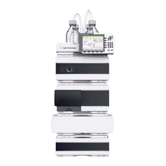
37 and Figure 6 on page 38). This configuration optimizes the flow path for minimum delay volume and minimizes the bench space required. Figure 5 Recommended Stack Configuration for 1260 Infinity (Front View) Agilent 1200 Infinity Series VWD - User Manual... - Page 38 Installing the Detector Optimizing the Stack Configuration Figure 6 Recommended Stack Configuration for 1260 Infinity (Rear View) Agilent 1200 Infinity Series VWD - User Manual...
- Page 39 The Agilent 1290 Infinity Binary Pump should always be installed at the bottom of the stack. Figure 7 Recommended stack configuration for 1290 Infinity with binary pump (front view) Agilent 1200 Infinity Series VWD - User Manual...
- Page 40 Installing the Detector Optimizing the Stack Configuration Figure 8 Recommended stack configuration 1290 Infinity with binary pump (rear view) Agilent 1200 Infinity Series VWD - User Manual...
-
Page 41: Two Stack Configuration
A slightly longer capillary is required between the pump and autosampler. (See Figure 9 on page 41 and Figure 10 on page 42). Figure 9 Recommended Two Stack Configuration for 1260 Infinity (Front View) Agilent 1200 Infinity Series VWD - User Manual... - Page 42 Installing the Detector Optimizing the Stack Configuration Figure 10 Recommended Two Stack Configuration for 1260 Infinity (Rear View) Agilent 1200 Infinity Series VWD - User Manual...
- Page 43 A slightly longer capillary is required between the pump and autosampler. (See Figure 11 on page 43 and Figure 12 on page 44). Figure 11 Recommended two stack configuration for 1290 Infinity with binary pump (front view) Agilent 1200 Infinity Series VWD - User Manual...
- Page 44 Installing the Detector Optimizing the Stack Configuration Figure 12 Recommended two stack configuration for 1290 Infinity with binary pump (rear view) Agilent 1200 Infinity Series VWD - User Manual...
-
Page 45: Installation Information On Leak And Waste Handling
A printed copy of the guideline has been shipped with the solvent cabinet, electronic copies are available on the Internet. Recommendations for Solvent Cabinet N O T E For details, see the usage guideline for the Agilent 1200 Infinity Series Solvent Cabinets. Agilent 1200 Infinity Series VWD - User Manual... - Page 46 Installing the Detector Installation Information on Leak and Waste Handling Figure 13 Leak and waste handling (overview - typical stack configuration as an example) Agilent 1200 Infinity Series VWD - User Manual...
- Page 47 Do not bend tubes. ➔ Do not immerse tube end in waste liquid. ➔ Do not intubate tubes in other tubes. ➔ For correct tubing follow instructions on label attached to the module. Agilent 1200 Infinity Series VWD - User Manual...
- Page 48 Installing the Detector Installation Information on Leak and Waste Handling Figure 14 Warning label (illustration for correct waste tubing) Agilent 1200 Infinity Series VWD - User Manual...
-
Page 49: Installing The Detector
If you want to use the "data-never-lost" feature, then assure that the CompactFlash Card is N O T E installed in the rear of the G1314E VWD. Agilent 1200 Infinity Series VWD - User Manual... - Page 50 4 Ensure the line power switch at the front of the detector is OFF. 5 Connect the power cable to the power connector at the rear of the detector. 6 Connect the CAN cable to other modules. Agilent 1200 Infinity Series VWD - User Manual...
- Page 51 To disconnect the detector from line, unplug the power cord. The power supply still uses N O T E some power, even if the power switch at the front panel is turned off. Agilent 1200 Infinity Series VWD - User Manual...
-
Page 52: Flow Connections To The Detector
The flow cell is shipped with a filling of isopropanol (also recommended when the N O T E instrument and/or flow cell is shipped to another location). This is to avoid breakage due to subambient conditions. Agilent 1200 Infinity Series VWD - User Manual... - Page 53 Press the flow cell completely into the slot and tighten Assemble the column-detector capillary. Depending on the cell screws (both parallel) until the mechanical stop. the flow cell type it may be a PEEK or SST capillary. Agilent 1200 Infinity Series VWD - User Manual...
- Page 54 The installation of the detector is now complete. The detector should be operated with the front cover in place to protect the flow cell area N O T E against strong drafts from the outside. Agilent 1200 Infinity Series VWD - User Manual...
-
Page 55: Using The Detector
Agilent 1200 Infinity Series VWD - User Manual Using the Detector Leak and Waste Handling Setting up an Analysis Before Using the System Requirements and Conditions Optimization of the System Preparing the HPLC System Running the Sample and Verifying the Results... -
Page 56: Leak And Waste Handling
To achieve maximal safety, check the correct installation regularly. Recommendations for Solvent Cabinet N O T E For details, see the usage guideline for the Agilent 1200 Infinity Series Solvent Cabinets. For details on correct installation, see “Installation Information on Leak and Waste Handling”... -
Page 57: Setting Up An Analysis
(when available in the system) and the pump. Solvents containing volatile ingredients will slightly lose these. Therefore priming of the pumping system is required before starting an application. Agilent 1200 Infinity Series VWD - User Manual... - Page 58 2 Flush all tubes with at least 30 mL of solvent. 3 Set flow to required value of your application and close the purge valve. Pump for approximately 10 minutes before starting your application. N O T E Agilent 1200 Infinity Series VWD - User Manual...
-
Page 59: Requirements And Conditions
59: Table 9 Conditions Flow 1.5 mL/min Stoptime 8 min Solvent 100% (30% water/70% Acetonitrile) Temperature Ambient Wavelength sample 254 nm Injection Volume 1 µL Column Temperature (optional): 25 °C or ambient Agilent 1200 Infinity Series VWD - User Manual... - Page 60 60. The exact profile of the chromatogram will depend on the chromatographic conditions. Variations in solvent quality, column packing, standard concentration and column temperature will all have a potential effect on peak retention and response. Figure 16 Typical Chromatogram with UV-detector Agilent 1200 Infinity Series VWD - User Manual...
-
Page 61: Optimization Of The System
Agilent ChemStation screen should look like shown in Figure 17 on page 61. The System status is red (Not Ready). Figure 17 Initial Agilent ChemStation screen (Method and Run Control) Agilent 1200 Infinity Series VWD - User Manual... - Page 62 System On button or the buttons below the module icons on the graphical user interface (GUI). After some time, the pump, thermostatted column compartment and detector module will turn to green. Figure 18 Turning on the HPLC Module Agilent 1200 Infinity Series VWD - User Manual...
- Page 63 7 For the isocratic pump, fill the solvent bottle with the mixture of HPLC- grade bi- distilled water (30 %) and acetonitrile (70 %). For binary- and quaternary pumps you can use separate bottles. Agilent 1200 Infinity Series VWD - User Manual...
- Page 64 8 Click on the Load Method button, select DEF_LC.M and press OK. Alternatively, double- click on the method in the method window. The default LC method parameters are transferred into the modules. Figure 20 Loading Default LC Method Agilent 1200 Infinity Series VWD - User Manual...
- Page 65 65) and open the Setup of these modules. Figure 22 on page 66 shows the detector settings (do not change the detector parameters at this time). Figure 21 Open the module menu Agilent 1200 Infinity Series VWD - User Manual...
- Page 66 (for diagnostics) • autobalance to zero absorbance (on the analog output plus offset) at begin and/or end of run • see “Special Setpoints” on page 76. Figure 22 Detector Settings (default) Agilent 1200 Infinity Series VWD - User Manual...
- Page 67 Change the Y- range for the VWD to 1 mAU and the offset to 20 % and the pressure offset to 50 %. The X- axis range should be 15 minutes. Press OK to exit this screen. Figure 23 Edit Signal Plot Window Agilent 1200 Infinity Series VWD - User Manual...
- Page 68 13 If both baselines are stable, set the Y- range for the detector signal to 100 mAU. If you start with a new UV-lamp for the first time, the lamp may show initial drift for some N O T E time (burn-in effect). Agilent 1200 Infinity Series VWD - User Manual...
- Page 69 Figure 25 Sample Information 15 Fill the content of an isocratic standard sample ampoule into a vial and seal the vial with a cap and place the vial into autosampler tray (position #1). Agilent 1200 Infinity Series VWD - User Manual...
-
Page 70: Running The Sample And Verifying The Results
ChemStation will show the resulting chromatogram. Figure 26 Chromatogram with Isocratic Test Sample Information about using the Data Analysis functions can be obtained from the Using your N O T E ChemStation manual supplied with your system. Agilent 1200 Infinity Series VWD - User Manual... -
Page 71: Special Settings Of The Detector
1 V full scale, see “Analog Output Settings” page 75. • Automatic Turn On: lamps can be programmed (detector must be on for this). • Help: online help. Figure 27 Detector control settings Agilent 1200 Infinity Series VWD - User Manual... -
Page 72: Configuration Settings
If the flow cell temperature is critical for your chromatography or your environment is N O T E stable, you may set the Temperature Control to off. This will lower the optical unit and flow cell temperature by some degree. Agilent 1200 Infinity Series VWD - User Manual... -
Page 73: Online Spectra
This online spectrum is taken during a stop-flow condition only while the peak is kept in the N O T E flow cell, see “Scanning with the VWD” on page 74. Figure 29 Online Spectra Window 2 Change the absorbance and wavelength range according your needs. Agilent 1200 Infinity Series VWD - User Manual... -
Page 74: Scanning With The Vwd
A sample scan is taken in the range defined under “Special Setpoints” page 76 and the Online Spectra window (see “Online Spectra” page 73) displays the result (Sample Scan minus Blank Scan). Agilent 1200 Infinity Series VWD - User Manual... -
Page 75: Analog Output Settings
• Attenuation Limits: 0.98 to 4000 mAU at discrete values for either 100 mV or 1 V full scale. Figure 30 Analog Output Settings Figure 31 Analog Output Settings 3 Change the values if required. Agilent 1200 Infinity Series VWD - User Manual... -
Page 76: Special Setpoints
N O T E 1 To change the Peakwidth settings select Setup Detector Signals. 2 In the section Peakwidth (Responsetime) click on the drop- down list. 3 Change the Peakwidth according to your needs. Agilent 1200 Infinity Series VWD - User Manual... - Page 77 Table 10 on page 78, Table 11 page 78 and Table 12 on page 79 . Figure 33 Peakwidth Setting Agilent 1200 Infinity Series VWD - User Manual...
- Page 78 Peak Width - Response Time - Data Rate (G1314F) peakwidth at half heigth Response Time [s] Data Rate [Hz] [min] <0.003125 <0.0625 >0.003125 0.0625 >0.00625 0.125 >0.0125 0.25 >0.025 >0.05 >0.1 >0.2 >0.4 1.25 Agilent 1200 Infinity Series VWD - User Manual...
- Page 79 Peak Width – Response Time – Data Rate (G1314E) peakwidth at half heigth Response Time [s] Data Rate [Hz] [min] <0.0012 <0.03 >0.0012 0.03 >0.0025 0.06 >0.005 0.12 >0.01 0.25 >0.025 >0.05 >0.1 >0.2 >0.4 1.25 Agilent 1200 Infinity Series VWD - User Manual...
-
Page 80: Run Recovery (G1314E)
When during recovery an error “Method/Sequence stopped” appears, the instrument N O T E logbook shows an entry “No Run data available in device“. In this case refer to “No Run Data Available In Device” on page 112. Agilent 1200 Infinity Series VWD - User Manual... - Page 81 If the detector status window is not opened, you will realize only the Power Fail error and N O T E the long Run In Progress information until the data is recovered from disk. Agilent 1200 Infinity Series VWD - User Manual...
- Page 82 When during recovery an error “Method/Sequence stopped” appears, the instrument N O T E logbook shows an entry “No Run data available in device“. In this case refer to “No Run Data Available In Device” on page 112. Agilent 1200 Infinity Series VWD - User Manual...
-
Page 83: How To Optimize The Detector
Agilent 1200 Infinity Series VWD - User Manual How to optimize the detector Optimizing the Detector Performance Match the Flow Cell to the Column Set the Detector Parameters This chapter gives hints on how to select the detector parameters and the flow cell. -
Page 84: Optimizing The Detector Performance
The information below will guide you on how to get the best detector performance. Follow these rules as a start for new applications. It gives a rule- of- thumb for optimizing the detector parameters. Agilent 1200 Infinity Series VWD - User Manual... -
Page 85: Match The Flow Cell To The Column
• If longer columns (> 50 mm) for higher resolution are used, then the next larger flow cell is the preferred choice for higher sensitivity. Agilent 1200 Infinity Series VWD - User Manual... - Page 86 To determine the volume of your peaks, take the peak width as reported in the integration results multiply it by the flow rate and divide it by 3). Agilent 1200 Infinity Series VWD - User Manual...
- Page 87 However you have to be aware that there is additional tolerance of gasket thickness and its N O T E compression ratio which is supposed to be very small in comparison with the machining tolerance. Agilent 1200 Infinity Series VWD - User Manual...
-
Page 88: Set The Detector Parameters
• preferably where the spectrum is flat for better linearity. 3 Consider to use time- programming to further optimization. Agilent 1200 Infinity Series VWD - User Manual... -
Page 89: Troubleshooting And Diagnostics
Agilent 1200 Infinity Series VWD - User Manual Troubleshooting and Diagnostics Overview of the Detector’s Indicators and Test Functions Status Indicators Power Supply Indicator Module Status Indicator Available Tests versus Interfaces Agilent Lab Advisor Software Overview about the troubleshooting and diagnostic features. -
Page 90: Overview Of The Detector's Indicators And Test Functions
“Wavelength Verification- Calibration” page 120. Diagnostic Signals The detector has several signals (internal temperatures, voltages and currents of lamps) that can be used for diagnosing baseline problems. Refer to the Service Manual for details. Agilent 1200 Infinity Series VWD - User Manual... -
Page 91: Status Indicators
Figure 37 Location of Status Indicators Power Supply Indicator The power supply indicator is integrated into the main power switch. When the indicator is illuminated (green) the power is ON. Agilent 1200 Infinity Series VWD - User Manual... -
Page 92: Module Status Indicator
In such a case try to re- boot the module or try a cold- start (see “Special Settings” on page 191). Then try a firmware update (see “Replacing the Module’s Firmware” on page 147). If this does not help, a main board replacement is required. Agilent 1200 Infinity Series VWD - User Manual... -
Page 93: Available Tests Versus Interfaces
Service Dialog for service only for service only (*) interface provides passed/fail information or a plot. (**) requires a comand via comand line (***) requires a comand via comand line in Service Mode Agilent 1200 Infinity Series VWD - User Manual... -
Page 94: Agilent Lab Advisor Software
Agilent LC or all the Agilent GCs and LCs configured on the lab intranet. Agilent Lab Advisor software provides diagnostic capabilities for all Agilent 1200 Infinity Series modules. This includes diagnostic capabilities, calibration procedures and maintenance routines for all the maintenance routines. -
Page 95: Error Information
Agilent 1200 Infinity Series VWD - User Manual Error Information What Are Error Messages General Error Messages Timeout Shutdown Remote Timeout Lost CAN Partner Leak Leak Sensor Open Leak Sensor Short Compensation Sensor Open Compensation Sensor Short Fan Failed Open Cover... - Page 96 No Run Data Available In Device Cover Violation This chapter describes the meaning of detector error messages, and provides information on probable causes and suggested actions how to recover from error conditions. Agilent 1200 Infinity Series VWD - User Manual...
-
Page 97: What Are Error Messages
In all cases, error propagation is done via the CAN bus or via an APG remote cable (see documentation for the APG interface). Agilent 1200 Infinity Series VWD - User Manual... -
Page 98: General Error Messages
An external instrument has generated a shutdown signal on the remote line. The module continually monitors the remote input connectors for status signals. A LOW signal input on pin 4 of the remote connector generates the error message. Agilent 1200 Infinity Series VWD - User Manual... -
Page 99: Remote Timeout
Exchange the remote cable. Defective remote cable. Check the instrument for defects (refer to the Defective components in the instrument instrument’s documentation). showing the not-ready condition. Agilent 1200 Infinity Series VWD - User Manual... -
Page 100: Lost Can Partner
Probable cause Suggested actions Ensure all fittings are tight. Loose fittings. Exchange defective capillaries. Broken capillary. Exchange flow cell components. Leaking flow cell. Agilent 1200 Infinity Series VWD - User Manual... -
Page 101: Leak Sensor Open
Probable cause Suggested actions Please contact your Agilent service Defective leak sensor. representative. Please contact your Agilent service Leak sensor incorrectly routed, being representative. pinched by a metal component. Agilent 1200 Infinity Series VWD - User Manual... -
Page 102: Compensation Sensor Open
If the resistance across the sensor falls below the lower limit, the error message is generated. Probable cause Suggested actions Please contact your Agilent service Defective main board. representative. Agilent 1200 Infinity Series VWD - User Manual... -
Page 103: Fan Failed
Please contact your Agilent service representative. The top foam was removed during operation. Please contact your Agilent service representative. Foam not activating the sensor. Please contact your Agilent service representative. Defective sensor or main board. Agilent 1200 Infinity Series VWD - User Manual... -
Page 104: Detector Error Messages
Top foam removed while lamp is on. representative. Exchange the lamp. Defective or non-Agilent lamp. Please contact your Agilent service Defective main board. representative. Please contact your Agilent service Defective power supply. representative. Agilent 1200 Infinity Series VWD - User Manual... -
Page 105: Uv Lamp: No Voltage
Ensure the lamp is connected. Lamp disconnected. Exchange the lamp. Defective or non-Agilent lamp. Please contact your Agilent service Defective power supply. representative. Please contact your Agilent service Defective main board. representative. Agilent 1200 Infinity Series VWD - User Manual... -
Page 106: No Heater Current
Switch on the lamp. Lamp is OFF. Ensure the flow cell is installed correctly. Incorrect flow cell installation. Clean/replace flow cell windows or remove air Flow cell contamination or air bubbles. bubbles. Agilent 1200 Infinity Series VWD - User Manual... -
Page 107: Wavelength Holmium Check Failed
If defective, please contact your Agilent service representative. • Run the grating-motor test to determine if the grating assembly is defective. If defective, please contact your Agilent service representative. Agilent 1200 Infinity Series VWD - User Manual... -
Page 108: Grating Or Filter Motor Errors
Please contact your Agilent service Motor is not connected. representative. Please contact your Agilent service Defective motor. representative. Please contact your Agilent service Defective/missing grating or filter. representative. Please contact your Agilent service Cable/connector defective. representative. Agilent 1200 Infinity Series VWD - User Manual... -
Page 109: Wavelength Test Failed
Please contact your Agilent service Motor is not connected. representative. Please contact your Agilent service Defective motor. representative. Please contact your Agilent service Defective/missing grating or filter. representative. Please contact your Agilent service Cable/connector defective. representative. Agilent 1200 Infinity Series VWD - User Manual... -
Page 110: Adc Hardware Error
Probable cause Suggested actions Please contact your Agilent service Defective sensor or main board. representative. Verify that the ambient conditions are within Detector is exposed to illegal ambient the allowed range. conditions. Agilent 1200 Infinity Series VWD - User Manual... -
Page 111: Illegal Temperature Value From Sensor At Air Inlet
As a result the temperature control is switched off. Probable cause Suggested actions Please contact your Agilent service Defective connector or cable. representative. Please contact your Agilent service Defective heater. representative. Agilent 1200 Infinity Series VWD - User Manual... -
Page 112: Heater Power At Limit
(e.g full data rate at 80 Hz plus full spectra plus all signals) during data buffering. Probable cause Suggested actions • Correct communication problem. CompactFlash Card is full. • Reduce data rate. Agilent 1200 Infinity Series VWD - User Manual... - Page 113 Probable cause Suggested actions Please contact your Agilent service The top foam was removed during representative. operation. Please contact your Agilent service Foam not activating the sensor. representative. Agilent 1200 Infinity Series VWD - User Manual...
- Page 114 Error Information Detector Error Messages Agilent 1200 Infinity Series VWD - User Manual...
-
Page 115: Test Functions
Agilent 1200 Infinity Series VWD - User Manual Test Functions Intensity Test Intensity Test Failed Cell Test Wavelength Verification-Calibration ASTM Drift and Noise Test Quick Noise Test Dark Current Test Dark Current Test Failed Holmium Oxide Test Holmium Oxide Test Failed This chapter describes the detector’s built in test functions. -
Page 116: Intensity Test
The Agilent Lab Advisor and the Instant Pilot evaluate three values automatically and display the limits for each value, the average, the minimum and the maximum of all data points and passed or failed for each value. Agilent 1200 Infinity Series VWD - User Manual... -
Page 117: Intensity Test Failed
Repeat the test with the flow cell removed. If the Flow cell windows dirty test passes, exchange the flow cell windows. Please contact your Agilent service representative. Optics defect Exchange the lamp. Defective lamp or optics. Agilent 1200 Infinity Series VWD - User Manual... -
Page 118: Cell Test
Clean/replace cell windows Mechanical problem Check cell position In the Agilent Instant Pilot G4208A, the photocurrent readings are available via More > Diagnosis > VWD > LampIntensity Test, see Figure 40 page 119. Agilent 1200 Infinity Series VWD - User Manual... - Page 119 Test Functions Cell Test Figure 39 Cell Test with Lab Advisor Checking the Photocurrent with the Instant Pilot Figure 40 Checking the Photocurrent with the Instant Pilot Agilent 1200 Infinity Series VWD - User Manual...
-
Page 120: Wavelength Verification-Calibration
• after exchange of the optical unit or VWM board, • at a regular interval, at least once per year (for example, prior to an Operational Qualification/Performance Verification procedure), and • when chromatographic results indicate the detector may require recalibration. Agilent 1200 Infinity Series VWD - User Manual... - Page 121 Test Functions Wavelength Verification-Calibration Wavelength Verification/Calibration with Agilent Lab Advisor Figure 41 Wavelength Verification/Calibration with Agilent Lab Advisor Agilent 1200 Infinity Series VWD - User Manual...
-
Page 122: Astm Drift And Noise Test
20 minutes. The test is done with HPLC- grade water flowing through the flow cell at 1 mL/min. On completion of the test, the noise result is displayed automatically. Figure 42 ASTM Drift and Noise Test with Agilent Lab Advisor Agilent 1200 Infinity Series VWD - User Manual... -
Page 123: Quick Noise Test
The cycles in the noise determination are not overlapping. In order to obtain reliable results, the lamp should be turned on for at least 10 minutes prior to measurement. Figure 43 Quick Noise Test with Agilent Lab Advisor Agilent 1200 Infinity Series VWD - User Manual... -
Page 124: Dark Current Test
During the test, the shutter is moved into the light path. Next, the leakage current from both diodes is measured. Figure 44 Dark Current Test with Agilent Lab Advisor Agilent 1200 Infinity Series VWD - User Manual... -
Page 125: Dark Current Test Failed
Please contact your Agilent service Defective sample or reference diode. representative. Please contact your Agilent service Defective sample or reference ADC board. representative. Please contact your Agilent service Defective main board. representative. Agilent 1200 Infinity Series VWD - User Manual... -
Page 126: Holmium Oxide Test
• after flow cell maintenance or repair. Interpreting the Results The test is passed successfully when all three wavelengths are within ± 1 nm of the expected value. This indicates the detector is calibrated correctly. Agilent 1200 Infinity Series VWD - User Manual... -
Page 127: Holmium Oxide Test Failed
OK, exchange the flow cell components. Run the holmium oxide filter test. If the test fails, Dirty or defective holmium oxide filter. contact your Agilent service representative. Please contact your Agilent service representative. Optical misalignment. Agilent 1200 Infinity Series VWD - User Manual... - Page 128 Test Functions Holmium Oxide Test Agilent 1200 Infinity Series VWD - User Manual...
-
Page 129: Maintenance And Repair
Agilent 1200 Infinity Series VWD - User Manual Maintenance and Repair Introduction to Maintenance Warnings and Cautions Overview of Maintenance Cleaning the Module Exchanging a Lamp Exchanging a Flow Cell Repairing the Flow Cells Using the Cuvette Holder Correcting Leaks Replacing Leak Handling System Parts Replacing the Module’s Firmware... -
Page 130: Introduction To Maintenance
The module is designed for easy maintenance. Maintenance can be done from the front with module in place in the system stack. There are no serviceable parts inside. N O T E Do not open the module. Agilent 1200 Infinity Series VWD - User Manual... -
Page 131: Warnings And Cautions
Repair work at the module can lead to personal injuries, e.g. shock hazard, when the cover is opened. ➔ Do not remove the cover of the module. ➔ Only certified persons are authorized to carry out repairs inside the module. Agilent 1200 Infinity Series VWD - User Manual... - Page 132 ➔ If you connect external equipment to the instrument, make sure that you only use accessory units tested and approved according to the safety standards appropriate for the type of external equipment. Agilent 1200 Infinity Series VWD - User Manual...
-
Page 133: Overview Of Maintenance
A pressure tightness test should be parts cleaning or cell windows. done after repair. exchange Leak sensor drying If leak has occurred. Check for leaks. Leak handling system If broken or corroded. Check for leaks. replacement Agilent 1200 Infinity Series VWD - User Manual... -
Page 134: Cleaning The Module
WA R N I N G hazard and damage the module ➔ Do not use an excessively damp cloth during cleaning. ➔ Drain all solvent lines before opening any connections in the flow path. Agilent 1200 Infinity Series VWD - User Manual... -
Page 135: Exchanging A Lamp
C A U T I O N ➔ To prevent accidental electrostatic discharge when coming into contact with components inside the instrument, touch one of the metal housing panels at the front of the instrument. Agilent 1200 Infinity Series VWD - User Manual... - Page 136 Press the release buttons and remove the front cover to Unscrew the heater assembly and remove it. have access to the front area. Unscrew, disconnect and remove the lamp. Insert, fix and Replace the heater assembly. reconnect the lamp. Agilent 1200 Infinity Series VWD - User Manual...
- Page 137 120 to check the correct positioning of the lamp. If the detector was turned off during the replacement, then the detector requires a warm-up N O T E time of 60 minutes. No measurements should be performed during this time. Agilent 1200 Infinity Series VWD - User Manual...
-
Page 138: Exchanging A Flow Cell
“High Pressure Flow Cell 10 mm / 14 µL” on page 158 Preparations Turn the lamp OFF. Press the release buttons and remove the front cover to Disconnect the inlet and outlet capillaries. have access to the flow cell area. Agilent 1200 Infinity Series VWD - User Manual... - Page 139 (outside of the cell compartment) and all capillary connections. Insert the flow cell. Perform “Wavelength Verification-Calibration” page 120 to check the correct positioning of the flow cell. Replace the front cover. Agilent 1200 Infinity Series VWD - User Manual...
-
Page 140: Repairing The Flow Cells
“High Pressure Flow Cell 10 mm / 14 µL” on page 158 The shown cell parts will differ depending upon the flow cell type. For detailed parts N O T E schematics, refer to above mentioned pages. Agilent 1200 Infinity Series VWD - User Manual... - Page 141 Use adhesive tape to remove the peek ring, the window and the gasket. d Repeat step a through step c for the other window (keep the parts separate - otherwise they could be mixed!). Agilent 1200 Infinity Series VWD - User Manual...
- Page 142 6 Perform a leak test. If OK, insert the flow cell. 7 Perform “Wavelength Verification- Calibration” on page 120 to check the correct positioning of the flow cell. 8 Replace the front cover. Agilent 1200 Infinity Series VWD - User Manual...
-
Page 143: Using The Cuvette Holder
If your own standard should be used to checkout the instrument. Parts required Description G1314-60200 Cuvette Holder Cuvette with the “standard”, e.g. NIST certified holmium oxide sample Preparations • Remove the normal flow cell. • Have cuvette with standard available. Agilent 1200 Infinity Series VWD - User Manual... - Page 144 Next Steps: Install the cuvette holder in the instrument. Perform your Wavelength Verification/Calibration “Wavelength Verification-Calibration” on page 120 to check the correct position of the cuvette holder. Agilent 1200 Infinity Series VWD - User Manual...
-
Page 145: Correcting Leaks
2 Use tissue to dry the leak sensor area. 3 Observe the capillary connections and the flow cell area for leaks and correct, if required. 4 Replace the front cover. Figure 48 Drying the Leak Sensor Agilent 1200 Infinity Series VWD - User Manual... -
Page 146: Replacing Leak Handling System Parts
5 Insert the leak funnel with the tubing in its position. 6 Insert the leak funnel into the leak funnel holder. 7 Replace the front cover. Figure 49 Replacing Waste Handling System Parts Agilent 1200 Infinity Series VWD - User Manual... -
Page 147: Replacing The Module's Firmware
1 Download the required module firmware, the latest LAN/RS- 232 FW Update Tool and the documentation from the Agilent web. • http://www.chem.agilent.com/_layouts/agilent/downloadFirmware.aspx?whid=69761 2 For loading the firmware into the module follow the instructions in the documentation. Agilent 1200 Infinity Series VWD - User Manual... - Page 148 Conversion to / Not possible due to different emulation of G1314B hardware and electronic or G1314C platform Agilent 1200 Infinity Series VWD - User Manual...
-
Page 149: Parts And Materials For Maintenance
Agilent 1200 Infinity Series VWD - User Manual Parts and Materials for Maintenance Overview of Maintenance Parts Standard Flow Cell 10 mm / 14 µL Micro Flow Cell 3 mm / 2 µL Semi-micro Flow Cell 6 mm / 5 µL High Pressure Flow Cell 10 mm / 14 µL... -
Page 150: Overview Of Maintenance Parts
“Micro Flow Cell 3 mm / 2 µL” on page 154, • “Semi- micro Flow Cell 6 mm / 5 µL” on page 156 and • “High Pressure Flow Cell 10 mm / 14 µL” on page 158. Agilent 1200 Infinity Series VWD - User Manual... -
Page 151: Kits
2 MT PTFE tubing i.d. 0.8 m, 1/16 o.d. 5063-6527 Tubing assembly, i.d. 6 mm, o.d. 9 mm, 1.2 m (to waste) 5181-1516 CAN cable, Agilent module to module, 0.5 m Agilent 1200 Infinity Series VWD - User Manual... -
Page 152: Standard Flow Cell 10 Mm / 14 Μl
Gasket #1 kit (OUT large hole, i.d. 2.4 mm) KAPTON, 2/pk G1314-65065 Ring #1 kit (OUT large hole, i.d. 2.4 mm) PEEK, 2/pk G1314-44010 Clip for RFI ID tag 0515-4780 Screw for Clip, M2.2, 4.5 mm long Agilent 1200 Infinity Series VWD - User Manual... - Page 153 Parts and Materials for Maintenance Standard Flow Cell 10 mm / 14 µL Figure 50 Standard Flow Cell Agilent 1200 Infinity Series VWD - User Manual...
-
Page 154: Micro Flow Cell 3 Mm / 2 Μl
Cell repair kit semi-micro, includes window screw kit, Gasket Kit BACK, Gasket Kit FRONT and 4 mm hexagonal wrench 79883-68703 Window screw kit, includes 2 quartz windows, 2 compression washers, 2 window holders, 2 window screws and 10 washers Agilent 1200 Infinity Series VWD - User Manual... - Page 155 Parts and Materials for Maintenance Micro Flow Cell 3 mm / 2 µL Figure 51 Micro Flow Cell Agilent 1200 Infinity Series VWD - User Manual...
-
Page 156: Semi-Micro Flow Cell 6 Mm / 5 Μl
Semi-micro #1 gasket (long hole 1.5 x 3.5 mm), PTFE Semi-micro #2 gasket (long hole 2 x 4 mm), PTFE G1314-44010 Clip for RFI ID tag 0515-4780 Screw for Clip, M2.2, 4.5 mm long Agilent 1200 Infinity Series VWD - User Manual... - Page 157 Parts and Materials for Maintenance Semi-micro Flow Cell 6 mm / 5 µL Figure 52 Semi-micro Flow Cell Agilent 1200 Infinity Series VWD - User Manual...
-
Page 158: High Pressure Flow Cell 10 Mm / 14 Μl
Cell kit Agilent, comprises: two windows, two KAPTON gaskets and two PEEK rings Ring PEEK kit Window quartz kit Gasket kit, KAPTON G1314-44010 Clip for RFI ID tag 0515-4780 Screw for Clip, M2.2, 4.5 mm long Agilent 1200 Infinity Series VWD - User Manual... - Page 159 Parts and Materials for Maintenance High Pressure Flow Cell 10 mm / 14 µL Figure 53 High Pressure Flow Cell Agilent 1200 Infinity Series VWD - User Manual...
-
Page 160: Cuvette Holder
Parts and Materials for Maintenance Cuvette Holder Cuvette Holder For information the use of the cuvette holder, refer to “Using the Cuvette Holder” on page 143. Description G1314-60200 Cuvette Holder Figure 54 Cuvette Holder Agilent 1200 Infinity Series VWD - User Manual... -
Page 161: Leak Parts
5041-8388 Leak funnel 5041-8389 Leak funnel holder 5041-8387 Tube clip 5062-2463 Corrugated tubing, PP, 6.5 mm id, 5 m 5062-2463 Corrugated tubing, PP, 6.5 mm id, 5 m Figure 55 Leak Parts Agilent 1200 Infinity Series VWD - User Manual... - Page 162 Parts and Materials for Maintenance Leak Parts Agilent 1200 Infinity Series VWD - User Manual...
-
Page 163: Identifying Cables
Agilent 1200 Infinity Series VWD - User Manual Identifying Cables Cable Overview Analog Cables Remote Cables BCD Cables CAN/LAN Cables RS-232 Cables This chapter provides information on cables used with the Agilent 1200 Infinity Series modules. Agilent Technologies... -
Page 164: Cable Overview
Identifying Cables Cable Overview Cable Overview Never use cables other than the ones supplied by Agilent Technologies to ensure proper N O T E functionality and compliance with safety or EMC regulations. Analog cables Description 35900-60750 Agilent module to 3394/6 integrators... - Page 165 It's also called "Null Modem Cable" with full handshaking where the wiring is made between pins 1-1, 2-3, 3-2, 4-6, 5-5, 6-4, 7-8, 8-7, 9-9. 5181-1561 RS-232 cable, 8 m Agilent 1200 Infinity Series VWD - User Manual...
-
Page 166: Analog Cables
Signal Name module Not connected Shield Analog - Center Analog + Agilent Module to BNC Connector p/n 8120-1840 Pin BNC Pin Agilent Signal Name module Shield Shield Analog - Center Center Analog + Agilent 1200 Infinity Series VWD - User Manual... - Page 167 Identifying Cables Analog Cables Agilent Module to General Purpose p/n 01046-60105 Pin Agilent Signal Name module Not connected Black Analog - Analog + Agilent 1200 Infinity Series VWD - User Manual...
-
Page 168: Remote Cables
Identifying Cables Remote Cables Remote Cables One end of these cables provides a Agilent Technologies APG (Analytical Products Group) remote connector to be connected to Agilent modules. The other end depends on the instrument to be connected to. Agilent Module to 3396A Integrators... - Page 169 6 - Yellow 6 - Yellow Power on High 7 - Red 7 - Red Ready High 8 - Green 8 - Green Stop 9 - Black 9 - Black Start request Agilent 1200 Infinity Series VWD - User Manual...
- Page 170 Wire Color Pin Agilent Signal Name Active module (TTL) White Digital ground Brown Prepare run Gray Start Blue Shut down Pink connected Yellow Power on High Ready High Green Stop Black Start request Agilent 1200 Infinity Series VWD - User Manual...
-
Page 171: Bcd Cables
BCD 0 Orange BCD 3 BCD 2 Brown BCD 1 Gray Digital ground Gray Gray/pink BCD 11 Red/blue BCD 10 White/green BCD 9 Brown/green BCD 8 not connected not connected + 5 V Agilent 1200 Infinity Series VWD - User Manual... - Page 172 Agilent Module to 3396 Integrators p/n 03396-60560 Pin 3396 Pin Agilent Signal Name BCD Digit module BCD 5 BCD 7 BCD 6 BCD 4 BCD0 BCD 3 BCD 2 BCD 1 Digital ground + 5 V Agilent 1200 Infinity Series VWD - User Manual...
-
Page 173: Can/Lan Cables
CAN cable, Agilent module to module, 1 m LAN Cables Description 5023-0203 Cross-over network cable, shielded, 3 m (for point to point connection) 5023-0202 Twisted pair network cable, shielded, 7 m (for point to point connection) Agilent 1200 Infinity Series VWD - User Manual... -
Page 174: Cables
It's also called "Null Modem Cable" with full handshaking where the wiring is made between pins 1-1, 2-3, 3-2, 4-6, 5-5, 6-4, 7-8, 8-7, 9-9. 5181-1561 RS-232 cable, 8 m Agilent 1200 Infinity Series VWD - User Manual... -
Page 175: Hardware Information
Agilent 1200 Infinity Series VWD - User Manual Hardware Information Firmware Description Electrical Connections Rear View of the Module Information on Instrument Serial Number Interfaces Overview Interfaces Setting the 8-bit Configuration Switch Special Settings Instrument Layout Early Maintenance Feedback (EMF) -
Page 176: Firmware Description
• run synchronization through APG remote, • error handling, • diagnostic functions, • or module specific functions like • internal events such as lamp control, filter movements, • raw data collection and conversion to absorbance. Agilent 1200 Infinity Series VWD - User Manual... - Page 177 Update of main system can be done in the resident system only. Update of the resident N O T E system can be done in the main system only. Main and resident firmware must be from the same set. Figure 56 Firmware Update Mechanism Agilent 1200 Infinity Series VWD - User Manual...
- Page 178 All these specific informations are described in the documentation provided with the firmware update tools. The firmware update tools, firmware and documentation are available from the Agilent web. • http://www.chem.agilent.com/_layouts/agilent/downloadFirmware.aspx?whid=69761 Agilent 1200 Infinity Series VWD - User Manual...
-
Page 179: Electrical Connections
There are no externally accessible fuses, because automatic electronic fuses are implemented in the power supply. Never use cables other than the ones supplied by Agilent Technologies to ensure proper N O T E functionality and compliance with safety or EMC regulations. -
Page 180: Rear View Of The Module
Hardware Information Electrical Connections Rear View of the Module Figure 57 Rear View of Detector The Compact Flash card slot is used for the G1314E VWD only. N O T E Agilent 1200 Infinity Series VWD - User Manual... -
Page 181: Information On Instrument Serial Number
• CN = China Alphabetic character A-Z (used by manufacturing) Alpha-numeric code 0-9, A-Z, where each combination unambiguously denotes a module (there can be more than one code for the same module) 00000 Serial number Agilent 1200 Infinity Series VWD - User Manual... -
Page 182: Interfaces
Hardware Information Interfaces Interfaces The Agilent 1200 Infinity Series modules provide the following interfaces: Table 18 Agilent 1200 Infinity Series Interfaces Module LAN/BCD RS-232 Analog Special (optional) (on-board) Remote Pumps G1310B Iso Pump G1311B Quat Pump G1311C Quat Pump VL G1312B Bin Pump K1312B Bin Pump Clinical Ed. - Page 183 G1321C FLD G1362A RID G4280A ELSD EXT Contact AUTOZERO Others G1170A Valve Drive G1316A/C TCC K1316C TCC Clinical Ed. G1322A DEG K1322A DEG Clinical Ed. G1379B DEG G4225A DEG K4225A DEG Clinical Ed. Agilent 1200 Infinity Series VWD - User Manual...
- Page 184 • LAN connector as interface to the control software • RS- 232C as interface to a computer • REMOTE connector as interface to other Agilent products • Analog output connector(s) for signal output Agilent 1200 Infinity Series VWD - User Manual...
-
Page 185: Overview Interfaces
• one start bit and one stop bit are always used (not selectable). The RS- 232C is designed as DCE (data communication equipment) with a 9- pin male SUB- D type connector. The pins are defined as: Agilent 1200 Infinity Series VWD - User Manual... - Page 186 Direction Function Ground Figure 58 RS-232 Cable Analog Signal Output The analog signal output can be distributed to a recording device. For details refer to the description of the module’s main board. Agilent 1200 Infinity Series VWD - User Manual...
- Page 187 APG Remote The APG Remote connector may be used in combination with other analytical instruments from Agilent Technologies if you want to use features as common shut down, prepare, and so on. Remote control allows easy connection between single instruments or systems to ensure coordinated analysis with simple coupling requirements.
- Page 188 START REQUEST (L) Request to start injection cycle (for example, by start key on any module). Receiver is the autosampler. Special Interfaces There is no special interface for this module. Agilent 1200 Infinity Series VWD - User Manual...
-
Page 189: Setting The 8-Bit Configuration Switch
• For boot/test modes switches 1+2 must be UP plus required mode. For normal operation use the default (best) settings. N O T E Figure 59 Location of Configuration Switch (example shows a G4212A DAD) Agilent 1200 Infinity Series VWD - User Manual... - Page 190 When selecting the mode TEST, the LAN settings are: Auto-Negotiation & Using Stored. N O T E For explanation of "Boot Resident System" and "Revert to Default Data (Coldstart)" refer to N O T E “Special Settings” on page 191. Agilent 1200 Infinity Series VWD - User Manual...
-
Page 191: Special Settings
It only uses basic functions of the operating system for example, for communication. In this mode the main firmware can be loaded (using update utilities). Table 22 Boot Resident Settings (On-board LAN) Mode Select TEST/BOOT Agilent 1200 Infinity Series VWD - User Manual... - Page 192 Save your methods and data before executing a forced cold start. If you use the following switch settings and power the instrument up again, a forced cold start has been completed. Table 23 Forced Cold Start Settings (On-board LAN) Mode Select TEST/BOOT Agilent 1200 Infinity Series VWD - User Manual...
-
Page 193: Instrument Layout
• the plastic layers help cushion the electronic and mechanical parts from physical shock, and • the metal inner cabinet shields the internal electronics from electromagnetic interference and also helps to reduce or eliminate radio frequency emissions from the instrument itself. Agilent 1200 Infinity Series VWD - User Manual... -
Page 194: Early Maintenance Feedback (Emf)
RFID tag lamp without RFID tag via Lab Advisor or Instant Pilot The detector provides the following EMF counters: • Deuterium Lamp On- Time • Number of UV lamp ignitions Agilent 1200 Infinity Series VWD - User Manual... -
Page 195: Using The Emf Counters
The next time the EMF counters exceed the new EMF limits, the EMF flag will be displayed, providing a reminder that maintenance needs to be scheduled. This function is only available via Agilent Lab Advisor or Instant Pilot. N O T E Agilent 1200 Infinity Series VWD - User Manual... - Page 196 Hardware Information Early Maintenance Feedback (EMF) Agilent 1200 Infinity Series VWD - User Manual...
-
Page 197: Lan Configuration
Agilent 1200 Infinity Series VWD - User Manual LAN Configuration What you have to do first TCP-IP parameter configuration Configuration Switches Initialization mode selection Dynamic Host Configuration Protocol (DHCP) General Information (DHCP) Setup (DHCP) Link configuration selection Automatic configuration with Bootp... -
Page 198: What You Have To Do First
Location of Configuration Switch and MAC Label 2 Connect the instrument's LAN interface to • the PC network card using a crossover network cable (point- to- point) • a hub or switch using a standard LAN cable. Agilent 1200 Infinity Series VWD - User Manual... -
Page 199: Tcp-Ip Parameter Configuration
TCP/IP parameters after power- on. The parameters may be derived from a Bootp cycle, non- volatile memory or initialized with known default values. The initialization mode is selected by the configuration switch, see Table 25 on page 201. Agilent 1200 Infinity Series VWD - User Manual... -
Page 200: Configuration Switches
Initialization (‘Init’) Mode Bootp, all switches down. For details see Figure 62 page 201 Link Configuration speed and duplex mode determined by auto-negotiation, for details see “Link configuration selection” on page 208 Agilent 1200 Infinity Series VWD - User Manual... -
Page 201: Initialization Mode Selection
They are not stored to the non- volatile memory of the module. Therefore, the parameters are lost with the next power cycle of the module. Figure 62 Bootp (Principle) Agilent 1200 Infinity Series VWD - User Manual... - Page 202 Use the initialization mode Bootp & Store carefully, because writing to the non-volatile N O T E memory takes time. Therefore, when the module shall obtain its parameters from a Bootp Server every time it is powered on, the recommended initialization mode is Bootp! Agilent 1200 Infinity Series VWD - User Manual...
- Page 203 Figure 65 Using Default (Principle) Using the default address in your local area network may result in network problems. Take N O T E care and change it to a valid address immediately. Agilent 1200 Infinity Series VWD - User Manual...
- Page 204 In the Using Default mode, the parameters stored in the memory of the module are not N O T E cleared automatically. If not changed by the user, they are still available, when switching back to the mode Using Stored. Agilent 1200 Infinity Series VWD - User Manual...
-
Page 205: Dynamic Host Configuration Protocol (Dhcp)
2 It may be necessary to fully qualify the hostname with the DNS suffix, e.g. 0030d3177321.country.company.com. 3 The DHCP server may reject the hostname proposed by the card and assign a name following local naming conventions. Agilent 1200 Infinity Series VWD - User Manual... -
Page 206: Setup (Dhcp)
0030d3177321. On the Instant Pilot the MAC address can be found under Details in the LAN section. Figure 67 LAN Setting on Instant Pilot Agilent 1200 Infinity Series VWD - User Manual... - Page 207 Firmware Update Tool) and use MAC address as host name, e.g. 0030d3177321. The LC system should become visible in the control software (see Note in section “General Information (DHCP)” on page 205). Agilent 1200 Infinity Series VWD - User Manual...
-
Page 208: Link Configuration Selection
Link Configuration speed and duplex mode determined by auto-negotiation manually set to 10 Mbps, half-duplex manually set to 10 Mbps, full-duplex manually set to 100 Mbps, half-duplex manually set to 100 Mbps, full-duplex Agilent 1200 Infinity Series VWD - User Manual... -
Page 209: Automatic Configuration With Bootp
Agilent BootP Service is installed on a server or PC on the LAN to provide central administration of IP addresses for Agilent instruments on a LAN. The BootP service must be running TCP/IP network protocol and cannot run a DHCP server. Agilent 1200 Infinity Series VWD - User Manual... -
Page 210: How Bootp Service Works
• Does the Firewall block the BootP service? Add the BootP service as an exception. • Is the LAN Interface using the BootP- mode instead of "Using Stored" or "Using Default" modes? Agilent 1200 Infinity Series VWD - User Manual... -
Page 211: Installation Of Bootp Service
9 The Destination Folder selection screen appears. Install BootP to the default folder or click Browse to choose another location. Click Next. The default location for installation is: C:\Program Files\Agilent\BootPService\ 10 Click Install to begin installation. Agilent 1200 Infinity Series VWD - User Manual... - Page 212 16 Start BootP Service in the Windows® services: On the Windows® desktop click right on Computer icon, select Manage > Services and Applications > Services. Select the Agilent BootP Service and click Start. Agilent 1200 Infinity Series VWD - User Manual...
-
Page 213: Two Methods To Determine The Mac Address
The MAC address is printed on a label on the rear of the module. It is the number below the barcode and after the colon (:) and usually begins with the letters AD, see Figure 60 on page 198 . 3 Turn on the instrument. Agilent 1200 Infinity Series VWD - User Manual... -
Page 214: Assigning Ip Addresses Using The Agilent Bootp Service
5 Close the log file before turning on another instrument. 6 Uncheck the Do you want to log BootP requests? box after configuring instruments to avoid having the logfile use up excessive disk space. Agilent 1200 Infinity Series VWD - User Manual... - Page 215 5 Make these entries for the instrument: • MAC address • Host name, Enter a Hostname of your choice. The Host Name must begin with "alpha" characters (i.e. LC1260) • IP address • Comment (optional) Agilent 1200 Infinity Series VWD - User Manual...
- Page 216 11 Use the PING utility to verify connectivity by opening a command window and typing: Ping 192.168.254.11 for example. The Tab File is located at C:\Documents and Settings\All Users\Application Data\Agilent\BootP\TabFile Agilent 1200 Infinity Series VWD - User Manual...
-
Page 217: Changing The Ip Address Of An Instrument Using The Agilent Bootp Service
1 From the Windows control panel, select Administrative Tools > Services. The Services screen appears. Figure 71 Windows Services screen 2 Right- click Agilent BootP Service. 3 Select Stop. 4 Close the Services and Administrative Tools screen. Agilent 1200 Infinity Series VWD - User Manual... - Page 218 1 In the Windows control panel, select Administrative Tools > Services. The Services screen appears, see Figure 71 on page 217. 2 Right- click Agilent BootP Service and select Start. 3 Close the Services and Administrative Tools screens. Agilent 1200 Infinity Series VWD - User Manual...
-
Page 219: Manual Configuration
Therefore, manual configuration can be done at any time. A power cycle is mandatory to make the stored parameters become the active parameters, given that the initialization mode selection switches are allowing it. Figure 73 Manual Configuration (Principle) Agilent 1200 Infinity Series VWD - User Manual... -
Page 220: With Telnet
When the connection was established successfully, the module responds with the following: Figure 75 A connection to the module is made 3 Type ? and press enter to see the available commands. Figure 76 Telnet Commands Agilent 1200 Infinity Series VWD - User Manual... - Page 221 Then press [Enter], where parameter refers to the configuration parameter you are defining, and value refers to the definitions you are assigning to that parameter. Each parameter entry is followed by a carriage return. Agilent 1200 Infinity Series VWD - User Manual...
- Page 222 Figure 77 Telnet - Current settings in “Using Stored“ mode 6 Change the IP address (in this example 134.40.27.99) and type “/” to list current settings. Figure 78 Telnet - Change IP settings Agilent 1200 Infinity Series VWD - User Manual...
- Page 223 Closing the Telnet Session If the Initialization Mode Switch is changed now to “Using Stored” mode, the instrument N O T E will take the stored settings when the module is re-booted. Agilent 1200 Infinity Series VWD - User Manual...
-
Page 224: With The Instant Pilot (G4208A)
Instant Pilot - LAN Configuration 5 Press the Edit button (only visible if not in Edit mode), perform the required changes and press the Done button. 6 Leave the screen by clicking Exit. Agilent 1200 Infinity Series VWD - User Manual... -
Page 225: Pc And User Interface Software Setup
This procedure describes the change of the TCP/IP settings on your PC to match the module’s default parameters in a local configuration (see also “Initialization mode selection” on page 201). Figure 81 Changing the TCP/IP settings of the PC Agilent 1200 Infinity Series VWD - User Manual... -
Page 226: User Interface Software Setup
LAN Configuration PC and User Interface Software Setup User Interface Software Setup Install you user interface software according the provided User Interface Software Setup Guide. Agilent 1200 Infinity Series VWD - User Manual... -
Page 227: Appendix
Agilent 1200 Infinity Series VWD - User Manual Appendix General Safety Information Safety Symbols General Safety Information Safety Standards Operation Radio Interference Sound Emission UV Radiation Solvent Information Declaration of Conformity for HOX2 Filter Agilent Technologies on Internet This chapter provides addition information on safety, legal and web. -
Page 228: General Safety Information
C A U T I O N alerts you to situations that could cause loss of data, or damage of equipment. ➔ Do not proceed beyond a caution until you have fully understood and met the indicated conditions. Agilent 1200 Infinity Series VWD - User Manual... -
Page 229: General Safety Information
Agilent Technologies assumes no liability for the customer’s failure to comply with these requirements. Ensure the proper usage of the equipment. - Page 230 When working with solvents, observe appropriate safety procedures (for example, goggles, safety gloves and protective clothing) as described in the material handling and safety data sheet by the solvent vendor, especially when toxic or hazardous solvents are used. Agilent 1200 Infinity Series VWD - User Manual...
-
Page 231: Radio Interference
Appendix Radio Interference Radio Interference Cables supplied by Agilent Technologies are screened to provide optimized protection against radio interference. All cables are in compliance with safety or EMC regulations. Test and Measurement If test and measurement equipment is operated with unscreened cables, or... -
Page 232: Sound Emission
This product has a sound pressure emission (at the operator position) < 70 dB. • Sound Pressure Lp < 70 dB (A) • At Operator Position • Normal Operation • According to ISO 7779:1988/EN 27779/1991 (Type Test) Agilent 1200 Infinity Series VWD - User Manual... -
Page 233: Uv Radiation
Typically the radiation values are much smaller than these limits: Table 33 UV radiation typical values Position Effective irradiance Lamp installed, 50 cm distance average 0.016 µW/cm Lamp installed, 50 cm distance maximum 0.14 µW/cm Agilent 1200 Infinity Series VWD - User Manual... -
Page 234: Solvent Information
• Halogenated solvents or mixtures which form radicals and/or acids, for example: → 2COCl 2CHCl + 2HCl This reaction, in which stainless steel probably acts as a catalyst, occurs quickly with dried chloroform if the drying process removes the stabilizing alcohol. Agilent 1200 Infinity Series VWD - User Manual... - Page 235 For example, a 1 % solution of acetic acid in methanol will attack steel. • Solutions containing strong complexing agents (for example, EDTA, ethylene diamine tetra- acetic acid). • Mixtures of carbon tetrachloride with 2- propanol or THF. Agilent 1200 Infinity Series VWD - User Manual...
-
Page 236: Declaration Of Conformity For Hox2 Filter
Appendix Declaration of Conformity for HOX2 Filter Declaration of Conformity for HOX2 Filter Agilent 1200 Infinity Series VWD - User Manual... -
Page 237: Agilent Technologies On Internet
Appendix Agilent Technologies on Internet Agilent Technologies on Internet For the latest information on products and services visit our worldwide web site on the Internet at: http://www.agilent.com Agilent 1200 Infinity Series VWD - User Manual... - Page 238 RS-232 cables band width 6.5 nm 24, 27, data rate analog sampling rate 30, 27, cable data recovery beam splitter Beer-Lambert overview declaration of conformity absorbance remote defect on arrival Agilent 1200 Infinity Series VWD - User Manual...
- Page 239 30, 27, holmium oxide test failed intensity test with RFID tag ignition without cover 103, type 30, 27, flow cells with RFID tag matching for application Agilent 1200 Infinity Series VWD - User Manual...
- Page 240 32, 29, cuvette holder exchanging lamps high pressure flow cell Noise Test exchanging leak handling leak parts noise, short term 24, 27, system micro flow cell Agilent 1200 Infinity Series VWD - User Manual...
- Page 241 147, Agilent 1200 Infinity Series VWD - User Manual...
- Page 242 UV radiation Agilent 1200 Infinity Series VWD - User Manual...
- Page 243 Index Agilent 1200 Infinity Series VWD - User Manual...
- Page 244 • using and optimizing, • troubleshooting and diagnose, • maintenance and repair, • parts identification, • hardware information, • safety and related information. © Agilent Technologies 2008, 2010-2012, 2013 Printed in Germany 11/2013 *G1314-90034* *G1314-90034* G1314- 90034 Rev. B Agilent Technologies...