Agilent Technologies 1260 Service Manual
Infinity micro degasser
Hide thumbs
Also See for 1260:
- User manual (282 pages) ,
- Quick start manual (98 pages) ,
- Operator's quick manual (16 pages)
Table of Contents
Advertisement
Advertisement
Chapters
Table of Contents

Related Manuals for Agilent Technologies 1260


Summary of Contents for Agilent Technologies 1260
- Page 1 Agilent 1260 Infinity Micro Degasser Service Manual Agilent Technologies...
- Page 2 1987) or any equivalent agency regulation or contract clause. Use, duplication or dis- closure of Software is subject to Agilent Technologies’ standard commercial license terms, and non-DOD Departments and Agencies of the U.S. Government will 1260 Infinity Micro Degasser Service Manual...
-
Page 3: Table Of Contents
Prevent Blocking of Solvent Filters Solvent Information 5 Optimizing Performance Increasing the Degasser Performance and Degassing Level 6 Troubleshooting and Diagnostics Overview of the Degasser's Indicators Status Indicators Hardware Symptoms 7 Maintenance Introduction to Maintenance and Repair 1260 Infinity Micro Degasser Service Manual... - Page 4 Micro Vacuum Degasser Parts 11 Cable overview Overview Remote Cable 12 Hardware Information Operating Principle 13 Appendix General Safety Information The Waste Electrical and Electronic Equipment "WEEE) Directive (2002/96/EC) Radio Interference Sound Emission Agilent Technologies on Internet 1260 Infinity Micro Degasser Service Manual...
-
Page 5: Introduction
1260 Infinity Micro Degasser Service Manual Introduction Introduction to the Micro Vacuum Degasser Agilent Technologies... -
Page 6: Introduction To The Micro Vacuum Degasser
Introduction to the Micro Vacuum Degasser Introduction to the Micro Vacuum Degasser The Agilent 1260 Infinity micro vacuum degasser, model G1379B, comprises a 4- channel vacuum container, including 4 micro structured membranes, and a vacuum pump. When the micro vacuum degasser is... -
Page 7: Site Requirements And Specifications
1260 Infinity Micro Degasser Service Manual Site Requirements and Specifications Site Requirements Physical Specifications Performance Specifications Agilent Technologies... -
Page 8: Site Requirements
➔ Always unplug the power cable before opening the cover. ➔ Do not connect the power cable to the instrument while the covers are removed. 1260 Infinity Micro Degasser Service Manual... - Page 9 Never operate your instrumentation from a power outlet that has no ground connection. ➔ Never use a power cord other than the Agilent Technologies power cord designed for your region. Use of unsupplied cables WA R N I N G Using cables not supplied by Agilent Technologies can lead to damage of the electronic components or personal injury.
- Page 10 Using power cords for unintended purposes can lead to personal injury or damage of electronic equipment. ➔ Never use the power cords that Agilent Technologies supplies with this instrument for any other equipment. Bench Space The module dimensions and weight (see...
-
Page 11: Physical Specifications
Operating altitude Up to 2000 m (6562 ft) Non-operating altitude Up to 4600 m (15091 ft) For storing the module Safety standards: IEC, CSA, Installation category II, Pollution degree 2 For indoor use only. 1260 Infinity Micro Degasser Service Manual... -
Page 12: Performance Specifications
Site Requirements and Specifications Performance Specifications Performance Specifications Table 2 Performance Specifications Agilent 1260 Infinity Vacuum Degasser Type Specification Maximum flow rate 0 - 5 ml/min per channel Number of channels Internal volume per channel Typically 1 ml per channel... -
Page 13: Installing The Micro Vacuum Degasser
1260 Infinity Micro Degasser Service Manual Installing the Micro Vacuum Degasser Unpacking the Micro Vacuum Degasser Accessory Kit Contents Optimizing the Stack Configuration Installing the Micro Vacuum Degasser Flow Connections to the Micro Vacuum Degasser Operational Hints for the Micro Vacuum Degasser... -
Page 14: Unpacking The Micro Vacuum Degasser
79. Please report missing or damaged parts to your local Agilent Technologies Sales and Service Office. Table 3 Vacuum Degasser Delivery Checklist Description Quantity Vacuum Degasser Power Cable Service Manual Accessory Kit (“Accessory Kit Contents” on page 14) Accessory Kit Contents 1260 Infinity Micro Degasser Service Manual... - Page 15 Connecting tubing (to connect to channels in series for increased performance) 2x G1322-67300 Kit of 4 solvent tubes including labels for connection degasser to MCGV (Quaternary Pump) 5062-2463 Corrugated tubing, PP, 6.5 mm id, 5 m 0100-1710 Mounting Tool for Tubing Connections 1260 Infinity Micro Degasser Service Manual...
-
Page 16: Optimizing The Stack Configuration
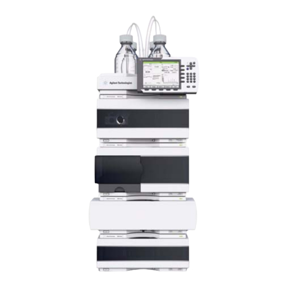
This configuration optimizes the system flow path, ensuring minimum delay volume (from point of solvent mixing to head of column) and dead volume (from point of injection to detector outlet). 1260 Infinity Micro Degasser Service Manual... - Page 17 Installing the Micro Vacuum Degasser Optimizing the Stack Configuration Figure 2 Recommended Stack Configuration (Front View) 1260 Infinity Micro Degasser Service Manual...
- Page 18 Installing the Micro Vacuum Degasser Optimizing the Stack Configuration Figure 3 Recommended Stack Configuration (Rear View) 1260 Infinity Micro Degasser Service Manual...
-
Page 19: Installing The Micro Vacuum Degasser
3 Connect the remote cable to the power connector at the rear of the micro vacuum degasser. 4 Option: Connect the interface cable to the micro vacuum degasser. The remote cable is a one way connection to send a not- ready signal from 1260 Infinity Micro Degasser Service Manual... - Page 20 APG remote cable to the other modules of the stack. An Agilent 1260 Infinity Instant Pilot can be connected to the CAN bus at any of the modules in the system except for the degasser. The control software can be connected to the system through one GPIB or LAN cable (via LAN-Card) at any of the modules (except for the degasser), preferably at the detector.
-
Page 21: Flow Connections To The Micro Vacuum Degasser
1 Place solvent cabinet with the bottle(s) on top of the micro vacuum degasser. 2 Remove the front cover by pressing the snap fasteners on both sides. Figure 6 Removing the Front Cover 1260 Infinity Micro Degasser Service Manual... - Page 22 Installing the Micro Vacuum Degasser Flow Connections to the Micro Vacuum Degasser 3 If the micro vacuum degasser is not used with an Agilent 1260 Infinity pump, connect the waste tube from the accessory kit to the waste outlet and place into your waste system.
- Page 23 Installing the Micro Vacuum Degasser Flow Connections to the Micro Vacuum Degasser Figure 8 FlowConnection to the Micro Vacuum Degasser 1260 Infinity Micro Degasser Service Manual...
-
Page 24: Operational Hints For The Micro Vacuum Degasser
3 Pump at low to moderate speed, until the solvent reaches into the pump. Pumping at higher flow rates will stress the system and might result in a failure to prime the degasser with the pump. 1260 Infinity Micro Degasser Service Manual... -
Page 25: Priming With A Syringe (Only Recommended If Priming With The Pump Fails)
7 Disconnect syringe adapter from solvent tube. 8 Connect solvent tube to your pump. 9 Repeat step 1 on page 25 to step 8 on page 25 for the other solvent channels. 1260 Infinity Micro Degasser Service Manual... - Page 26 The solvent at the degasser outlet will therefore not be fully degassed. Pump for approximately 5 minutes with your selected flow rate before starting any application. This will allow the micro vacuum degasser to properly degas the solvent in the degasser tubes. 1260 Infinity Micro Degasser Service Manual...
-
Page 27: Transporting The Micro Vacuum Degasser
1 Pull the solvent inlet tubing out of the solvent bottle of channel A. 2 Let the pump draw solvent and air through channel A of the degasser, until the chamber of channel A is completely dry. 3 Repeat these steps for the remaining solvent channels. 1260 Infinity Micro Degasser Service Manual... - Page 28 Installing the Micro Vacuum Degasser Transporting the Micro Vacuum Degasser 1260 Infinity Micro Degasser Service Manual...
-
Page 29: Using The Micro Vacuum Degasser
1260 Infinity Micro Degasser Service Manual Using the Micro Vacuum Degasser When to Use a Micro Vacuum Degasser? Prevent Blocking of Solvent Filters Solvent Information Material Information Agilent Technologies... -
Page 30: When To Use A Micro Vacuum Degasser
➔ Never operate your instrumentation under conditions other than those specified by the vendor. For capillary LC application with our Agilent 1260 Infinity Capillary and Nano LC System For high- pressure mixing pumps (binary and binary SL) with low flow rates or when you have following conditions: •... - Page 31 Using the Micro Vacuum Degasser When to Use a Micro Vacuum Degasser? • baseline drift in electrochemical detectors due to dissolved oxygen especially in reduction mode. 1260 Infinity Micro Degasser Service Manual...
-
Page 32: Prevent Blocking Of Solvent Filters
• Remove the blocked solvent filter from the bottle- head assembly and place it in a beaker with concentrated nitric acid (35%) for one hour. • Thoroughly flush the filter with bidistilled water (remove all nitric acid). • Replace the filter. 1260 Infinity Micro Degasser Service Manual... - Page 33 Using the Micro Vacuum Degasser Prevent Blocking of Solvent Filters Never use the system without solvent filter installed. N O T E 1260 Infinity Micro Degasser Service Manual...
-
Page 34: Solvent Information
• Mixtures of carbon tetrachloride with 2- propanol or THF dissolve stainless steel. Material Information Materials in Flow Path Following materials are used in the flow path of this module: 1260 Infinity Micro Degasser Service Manual... - Page 35 1 to 12.5 and inert to many common solvents. There are several known incompatibilities with chemicals such as chloroform, methylene chloride, THF, DMSO > 1 %, strong acids (nitric acid > 10 %, 1260 Infinity Micro Degasser Service Manual...
- Page 36 Agilent uses UHMW (ultra- high molecular weight)- PE/PTFE blends for yellow piston and wash seals, which are used in 1290 Infinity pumps and for normal phase applications in 1260 Infinity pumps. Polyethylene has a good stability for most common inorganic solvents including acids and bases in a pH range of 1 to 12.5 .
- Page 37 Fused silica is used in 1290 Infinity Flow Cells and capillaries. Quartz is used for classical flow cell windows. It is inert against all common solvents and acids except hydrofluoric acid and acidic solvents containing 1260 Infinity Micro Degasser Service Manual...
- Page 38 HFIP, it is best to dedicate a particular chamber to this solvent, not to switch solvents, and not to let dry out the chamber. For optimizing the life of the pressure sensor, do not leave HFIP in the chamber when the unit is off. 1260 Infinity Micro Degasser Service Manual...
- Page 39 Solvent Information Sapphire, Ruby and Al -based ceramics Sapphire, ruby and ceramics based on aluminum oxide Al are inert to almost all common acids, bases and solvents. There are no documented incompatibilities for HPLC applications. 1260 Infinity Micro Degasser Service Manual...
- Page 40 Using the Micro Vacuum Degasser Solvent Information 1260 Infinity Micro Degasser Service Manual...
- Page 41 1260 Infinity Micro Degasser Service Manual Optimizing Performance Increasing the Degasser Performance and Degassing Level Agilent Technologies...
-
Page 42: Optimizing Performance Increasing The Degasser Performance And Degassing Level
3 Connect a degasser to pump connecting tubing (Kit of 4 solvent tubes for connection degasser to MCGV including labels (G1322- 67300)) to the outlet of the 2nd channel of the degasser and into the pump. Figure 9 Connecting two degasser channels in series 1260 Infinity Micro Degasser Service Manual... -
Page 43: Troubleshooting And Diagnostics
1260 Infinity Micro Degasser Service Manual Troubleshooting and Diagnostics Overview of the Degasser's Indicators Status Indicators Instrument Status Indicator Hardware Symptoms All Lamps are Off If the Status Indicator is Red If the Status Indicator is Yellow and the Vacuum Pump is not... -
Page 44: Overview Of The Degasser's Indicators
The micro vacuum degasser generates an error output on the remote lines. The following pages describe hardware symptoms which help you to isolate the cause of a hardware failure (see “Hardware Symptoms” on page 47). 1260 Infinity Micro Degasser Service Manual... -
Page 45: Status Indicators
• An error condition is indicated, when the lamp is red. An error condition exists when the micro vacuum degasser detects an internal 1260 Infinity Micro Degasser Service Manual... - Page 46 ➔ To prevent any damage, switch off the micro vacuum degasser and remove the solvent bottles from the solvent cabinet to stop any gravity-caused flow of solvent into the vacuum chamber. 1260 Infinity Micro Degasser Service Manual...
-
Page 47: Hardware Symptoms
“Installing the Micro Vacuum Degasser” on page 19. The vacuum degasser itself is not able to generate any error messages in the Agilent 1260 Infinity system logbook. The following pages describe hardware symptoms which help you to isolate the cause of a hardware failure. -
Page 48: If The Status Indicator Is Red
CN2 to the pump). If the windings are broken or shortened replace the vacuum pump (see “Exchanging the Vacuum Pump” page 70). 1260 Infinity Micro Degasser Service Manual... -
Page 49: Status Indicator Becomes Red And Vacuum Pump Was Running
If the vacuum cannot be reached, the micro vacuum degasser will be forced into an error state. The error condition can be reset by turning the micro vacuum degasser off and on again. 1260 Infinity Micro Degasser Service Manual... - Page 50 Troubleshooting and Diagnostics Hardware Symptoms The following parts can be responsible for an insufficient vacuum: 1 Leaky tubing, 2 Leaky chambers, 3 Defective proportional valve, 4 Defective pump, 5 Defective electronics. 1260 Infinity Micro Degasser Service Manual...
-
Page 51: Maintenance
1260 Infinity Micro Degasser Service Manual Maintenance Introduction to Maintenance and Repair Simple Repairs Warnings and Cautions Cleaning the Instrument Removing and Refitting the Top Cover Assembling the Main Cover Exchanging the Fuses of the Power Inline Filter Exchanging the Status Light Pipe... -
Page 52: Introduction To Maintenance And Repair
When defective Power Inline Filter” on page 60 “Removing and Refitting the Top Cover” on page 55 “Assembling the Main Cover” If broken page 58 “Exchanging the Status Light If broken Pipe” on page 62 1260 Infinity Micro Degasser Service Manual... -
Page 53: Warnings And Cautions
➔ Be sure to hold the board by the edges and do not touch the electrical components. Always use an ESD protection (for example, an ESD wrist strap) when handling electronic boards and components. 1260 Infinity Micro Degasser Service Manual... -
Page 54: Cleaning The Instrument
Do not use an excessively damp cloth that liquid can drip into the micro vacuum degasser. 1260 Infinity Micro Degasser Service Manual... -
Page 55: Removing And Refitting The Top Cover
Remove the front panel. Unclip the clips on the top cover. 1260 Infinity Micro Degasser Service Manual... - Page 56 Replace the top cover. Ensure the clips are seated of the plate first, then slide panel to the back. Assure the correctly. four metal tabs of the panel slide underneath the Z-plane. Fix the two holding screws. 1260 Infinity Micro Degasser Service Manual...
- Page 57 Maintenance Introduction to Maintenance and Repair Reinstall the front cover. Reinstall the micro vacuum degasser in your system stack and connect the cables and capillaries and turn on the vacuum degasser. 1260 Infinity Micro Degasser Service Manual...
-
Page 58: Assembling The Main Cover
The cover kit contains all parts, but it is not assembled. N O T E Place the top part on the bench and insert the left and Replace the cover. right side into the top part. 1260 Infinity Micro Degasser Service Manual... - Page 59 Maintenance Introduction to Maintenance and Repair Next Steps: Replace the micro vacuum degasser in the stack and reconnect the cables and capillaries. Turn on the vacuum degasser. 1260 Infinity Micro Degasser Service Manual...
-
Page 60: Exchanging The Fuses Of The Power Inline Filter
11). It accepts any line voltage in the range mentioned in the table. Consequently there is no voltage selector in the rear of the Agilent 1260 Infinity micro vacuum degasser. There are two externally accessible fuses, that protect the power supply. - Page 61 (approximately 0 Ohm). 6 If a fuse is defective (wire broken or high resistance), insert a new fuse. 7 Reinsert the fuse holders and the power cable. 8 Switch on the power switch. 1260 Infinity Micro Degasser Service Manual...
-
Page 62: Exchanging The Status Light Pipe
“Removing and Refitting the Top Cover” on page 55. 1 The status light pipe is clipped into the top cover. 2 Replace the top cover, see “Removing and Refitting the Top Cover” page 55. 1260 Infinity Micro Degasser Service Manual... -
Page 63: Repairs
1260 Infinity Micro Degasser Service Manual Repairs Exchanging Internal Parts Overview of Repair Procedures Overview of Internal Parts Exchanging a Vacuum Chamber Exchanging the Vacuum Pump Exchanging the Proportional Valve Exchanging the Vacuum Tubings Exchanging the Degasser Control Assembly and the Sensor... -
Page 64: Exchanging Internal Parts
Pressure reading above 500 mV Valve” on page 72 “Exchanging the Vacuum Tubings” on page 74 “Exchanging the Degasser Control If defective Low voltage at control assembly Assembly and the Sensor Assembly” on page 76 1260 Infinity Micro Degasser Service Manual... -
Page 65: Overview Of Repair Procedures
Repairs Overview of Repair Procedures Overview of Repair Procedures Figure 13 Overview of Repair Procedures 1260 Infinity Micro Degasser Service Manual... -
Page 66: Overview Of Internal Parts
Overview of Internal Parts Figure 14 on page 67 shows a top view of the micro vacuum degasser. It shows the connections of the vacuum tubes as well as the electrical connections at the control assembly. 1260 Infinity Micro Degasser Service Manual... - Page 67 Repairs Overview of Internal Parts Figure 14 Top View of the Micro Vacuum Degasser 1260 Infinity Micro Degasser Service Manual...
-
Page 68: Exchanging A Vacuum Chamber
7 Loosen the 2 screws which maintain the vacuum chamber leak reservoir. 8 Slide the reservoir out of the Z- plane. 9 Remove the suspect chamber and install the new one. 10 Put the reservoir in place. 1260 Infinity Micro Degasser Service Manual... - Page 69 13 Reconnect all inlet and outlet tubes to the vacuum chamber, see Figure 8 on page 23. 14 Refit the cover, see “Removing and Refitting the Top Cover” on page 55. Figure 15 Exchanging a Vacuum C hamber 1260 Infinity Micro Degasser Service Manual...
-
Page 70: Exchanging The Vacuum Pump
7 Place the vacuum pump in its position. 8 Place the fixing plates onto the rubber feet of the pump. 9 Insert the holding screws and fix them. 10 Connect the vacuum pump cable to the control assembly (CN1). 1260 Infinity Micro Degasser Service Manual... - Page 71 Repairs Overview of Internal Parts 11 Refit the cover, see “Removing and Refitting the Top Cover” on page 55. Figure 16 Exchanging the Vacuum Pump 1260 Infinity Micro Degasser Service Manual...
-
Page 72: Exchanging The Proportional Valve
7 Connect the two vacuum tubes to the valve. The inlet of the valve is labeled IN and is connected to the vacuum pump. 8 Fix the valve with the two screws to its holder. 9 Connect the valve cable to the control board (CN8). 1260 Infinity Micro Degasser Service Manual... - Page 73 Repairs Overview of Internal Parts 10 Refit the cover, see “Removing and Refitting the Top Cover” on page 55. Figure 17 Exchanging the Proportional Valve 1260 Infinity Micro Degasser Service Manual...
-
Page 74: Exchanging The Vacuum Tubings
Please refer to the drawing below for correct installation of all tubing. Pay particular attention to the correct installation of the waste outlet tubing (drawn in blue color). 1260 Infinity Micro Degasser Service Manual... - Page 75 Repairs Overview of Internal Parts 6 Refit the cover, see “Removing and Refitting the Top Cover” on page 55. Figure 18 Exchanging the Vacuum Tubing 1260 Infinity Micro Degasser Service Manual...
-
Page 76: Exchanging The Degasser Control Assembly And The Sensor Assembly
6 Lift the degasser control assembly out of the unit. 7 Remove the coupler from the control assembly and place it onto the power switch in the exchange control assembly. 1260 Infinity Micro Degasser Service Manual... - Page 77 13 Connect all the cables to the control board (sensor assembly cable to CN3, proportional valve cable to CN8, pump cable to CN1). 14 Refit the cover, see “Removing and Refitting the Top Cover” on page 55. Figure 19 Exchanging the Degasser Control Assembly 1260 Infinity Micro Degasser Service Manual...
- Page 78 Repairs Overview of Internal Parts 1260 Infinity Micro Degasser Service Manual...
-
Page 79: Parts And Materials For Maintenance
1260 Infinity Micro Degasser Service Manual Parts and Materials for Maintenance Cover Parts Sheet Metal Kit Power and Status Light Pipes Accessory Kit Agilent Technologies... -
Page 80: Cover Parts
Cover Parts Item Description 5065-9989 Cover kit (includes base, top, left and right) 5065-9990 Front cover 5042-8901 Name plate 5041-8365 Blank plug for unused channels 5041-8387 Tube clip (not shown) Figure 20 Cover Parts 1260 Infinity Micro Degasser Service Manual... -
Page 81: Sheet Metal Kit
Parts and Materials for Maintenance Sheet Metal Kit Sheet Metal Kit Item Description G1379-68702 Sheet metal kit G1379B includes base and top plate Figure 21 Sheet Metal Kit 1260 Infinity Micro Degasser Service Manual... -
Page 82: Power And Status Light Pipes
Power and Status Light Pipes Power and Status Light Pipes Item Description 5041-8383 Power switch coupler 5041-8382 Power switch light pipe 5041-8381 Power switch button 5041-8384 Status light pipe Figure 22 Power and Status Light Pipes 1260 Infinity Micro Degasser Service Manual... -
Page 83: Accessory Kit
Connecting tubing (to connect to channels in series for increased performance) 2x G1322-67300 Kit of 4 solvent tubes including labels for connection degasser to MCGV (Quaternary Pump) 5062-2463 Corrugated tubing, PP, 6.5 mm id, 5 m 0100-1710 Mounting Tool for Tubing Connections 1260 Infinity Micro Degasser Service Manual... - Page 84 Parts and Materials for Maintenance Accessory Kit 1260 Infinity Micro Degasser Service Manual...
-
Page 85: Parts For Repair
1260 Infinity Micro Degasser Service Manual Parts for Repair Micro Vacuum Degasser Parts Agilent Technologies... -
Page 86: Micro Vacuum Degasser Parts
Fuse: 250V, T 500 mA , compatible to all supported line voltages G1322-43100 Board clip G1379-60003 Proportional valve PN 5042-8922 Tubing set for G1379B Fixing plate G1379-60000 Vacuum pump G1379-27300 Leak tray internal G1379-47310 Leak pan, degasser 1260 Infinity Micro Degasser Service Manual... - Page 87 Parts for Repair Micro Vacuum Degasser Parts 1260 Infinity Micro Degasser Service Manual...
- Page 88 Parts for Repair Micro Vacuum Degasser Parts 1260 Infinity Micro Degasser Service Manual...
-
Page 89: Cable Overview
1260 Infinity Micro Degasser Service Manual Cable overview Overview Remote Cable Agilent Technologies... -
Page 90: Overview
Cable overview Overview Overview Never use cables other than the ones supplied by Agilent Technologies to ensure proper N O T E functionality and compliance with safety or EMC regulations. Analog cables Description 35900-60750 Agilent module to 3394/6 integrators 35900-60750... - Page 91 It's also called "Null Modem Cable" with full handshaking where the wiring is made between pins 1-1, 2-3, 3-2, 4-6, 5-5, 6-4, 7-8, 8-7, 9-9. 5181-1561 RS-232 cable, 8 m 1260 Infinity Micro Degasser Service Manual...
-
Page 92: Remote Cable
Cable overview Remote Cable Remote Cable One end of these cables provides a Agilent Technologies APG (Analytical Products Group) remote connector to be connected to Agilent modules. The other end depends on the instrument to be connected to. Agilent Module to 3396A Integrators... - Page 93 3 - Gray Start 4 - Blue Shut down 5 - Pink connected 6 - Yellow Power on High 7 - Red Ready High 8 - Green Stop 9 - Black Start request 13, 15 connected 1260 Infinity Micro Degasser Service Manual...
- Page 94 01046-60201 Wire Color Pin Agilent Signal Name Active module (TTL) White Digital ground Brown Prepare run Gray Start Blue Shut down Pink connected Yellow Power on High Ready High Green Stop Black Start request 1260 Infinity Micro Degasser Service Manual...
-
Page 95: Hardware Information
1260 Infinity Micro Degasser Service Manual Hardware Information Operating Principle This chapter describes the degasser in more detail on hardware and electronics. Agilent Technologies... -
Page 96: Operating Principle
(pump rate 1), the pump is switched to a constant voltage of 24 V (pump rate 2). • The ERROR mode (red status indicator) is activated in case the degasser cannot achieve a vacuum level of 180 Torr. (1 Torr = 1.33x10 bar) 1260 Infinity Micro Degasser Service Manual... -
Page 97: Appendix
1260 Infinity Micro Degasser Service Manual Appendix General Safety Information The Waste Electrical and Electronic Equipment "WEEE) Directive (2002/96/EC) Radio Interference Sound Emission Agilent Technologies on Internet This chapter provides additional information on safety, legal and web. Agilent Technologies... -
Page 98: General Safety Information
Agilent Technologies assumes no liability for the customer’s failure to comply with these requirements. Ensure the proper usage of the equipment. - Page 99 When working with solvents, observe appropriate safety procedures (for example, goggles, safety gloves and protective clothing) as described in the material handling and safety data sheet by the solvent vendor, especially when toxic or hazardous solvents are used. 1260 Infinity Micro Degasser Service Manual...
- Page 100 C A U T I O N alerts you to situations that could cause loss of data, or damage of equipment. ➔ Do not proceed beyond a caution until you have fully understood and met the indicated conditions. 1260 Infinity Micro Degasser Service Manual...
-
Page 101: The Waste Electrical And Electronic Equipment "Weee) Directive (2002/96/Ec)
Monitoring and Control Instrumentation product. Do not dispose off in domestic household waste N O T E To return unwanted products, contact your local Agilent office, or see www.agilent.com more information. 1260 Infinity Micro Degasser Service Manual... -
Page 102: Radio Interference
Appendix Radio Interference Radio Interference Cables supplied by Agilent Technologies are screened to provide optimized protection against radio interference. All cables are in compliance with safety or EMC regulations. Test and Measurement If test and measurement equipment is operated with unscreened cables, or... -
Page 103: Sound Emission
This product has a sound pressure emission (at the operator position) < 70 dB. • Sound Pressure Lp < 70 dB (A) • At Operator Position • Normal Operation • According to ISO 7779:1988/EN 27779/1991 (Type Test) 1260 Infinity Micro Degasser Service Manual... -
Page 104: Agilent Technologies On Internet
Appendix Agilent Technologies on Internet Agilent Technologies on Internet For the latest information on products and services visit our worldwide web site on the Internet at: http://www.agilent.com 1260 Infinity Micro Degasser Service Manual... - Page 105 RS-232 non-operating altitude CAN cable GPIB cable non-operating temperature changing solvents number of channels cleaning the instrument condensation hardware symptoms control assembly highest injection precision operating Altitude control circuit 1260 Infinity Micro Degasser Service Manual...
- Page 106 #1 tool radio interference mounting tool ready condition top cover, removing and refitting remote cable transportation remote cable vacuum chamber vacuum pump safety class I voltage range 1260 Infinity Micro Degasser Service Manual...
- Page 107 Index 1260 Infinity Micro Degasser Service Manual...
- Page 108 In This Book This manual contains service information about the Agilent 1260 Infinity Micro Degasser. The manual describes the following: • introduction, • site requirements and specifictions, • installing the micro degasser, • using the micro degasser, • optimizing performance, •...