Agilent Technologies 1260 Infinity User Manual
Variable wavelength
detector
Hide thumbs
Also See for 1260 Infinity:
- User manual (282 pages) ,
- Service manual (108 pages) ,
- Quick start manual (98 pages)

Related Manuals for Agilent Technologies 1260 Infinity


Summary of Contents for Agilent Technologies 1260 Infinity
- Page 1 Agilent 1260 Infinity Variable Wavelength Detector User Manual...
- Page 2 Defense purchases, DFARS 252.227-7015 (Technical Data - Commercial Items) and DFARS 227.7202-3 (Rights in Commercial Computer Software or Computer Software Documentation). If a federal government or other public sector Customer has a need for Agilent 1260 Infinity Variable Wavelength Detector User Manual...
- Page 3 In This Manual… This manual covers the Agilent 1260 Infinity Variable Wavelength Detectors G1314B Agilent 1260 Infinity Variable Wavelength Detector VL G1314C Agilent 1260 Infinity Variable Wavelength Detector VL+ Introduction to the Variable Wavelength Detector This chapter gives an introduction to the detector, instrument overview and internal connectors.
- Page 4 This chapter provides information on parts for maintenance. Identifying Cables This chapter provides information on cables used with the Agilent 1260 Infinity modules. Appendix This chapter provides addition information on safety, legal and web. Agilent 1260 Infinity Variable Wavelength Detector User Manual...
-
Page 5: Table Of Contents
Setting the 8-bit Configuration Switch (On-Board LAN) Setting the 8-bit Configuration Switch (without On-Board LAN) Communication Settings for RS-232C Special Settings Site Requirements and Specifications Site Requirements Power Consideration Power Cords Bench Space Environment Physical Specifications Agilent 1260 Infinity Variable Wavelength Detector User Manual... - Page 6 Preparing the HPLC System Running the Sample and Verifying the Results Special Settings of the Detector Control Settings Online Spectra Scanning with the VWD Analog Output Settings Special Setpoints Peakwidth Settings Optimizing the Detector Agilent 1260 Infinity Variable Wavelength Detector User Manual...
- Page 7 Timeout Shut-Down Remote Timeout Synchronization Lost Leak Leak Sensor Open Leak Sensor Short Compensation Sensor Open Compensation Sensor Short Fan Failed Open Cover Detector Error Messages Lamp Current Missing Lamp Voltage Missing Agilent 1260 Infinity Variable Wavelength Detector User Manual...
- Page 8 Quick Noise Test Dark Current Test Holmium Oxide Test D/A Converter (DAC)Test Grating and Filter Motor Test Test Chromatogram Procedure Using the Agilent LabAdvisor Maintenance and Repair Introduction to Maintenance Warnings and Cautions Agilent 1260 Infinity Variable Wavelength Detector User Manual...
- Page 9 Replacing the Detector’s Firmware Parts and Materials for Maintenance Overview of Maintenance Parts Standard Flow Cell Micro Flow Cell Semi-micro Flow Cell High Pressure Flow Cell Cuvette Holder Leak Parts Accessory Kit Agilent 1260 Infinity Variable Wavelength Detector User Manual...
- Page 10 RS-232 Cable External Contact Cable Appendix General Safety Information Safety Standards Safety Symbols Lithium Batteries Information Radio Interference Sound Emission UV-Radiation Solvent Information Declaration of Conformity for HOX2 Filter Agilent Technologies on Internet Agilent 1260 Infinity Variable Wavelength Detector User Manual...
- Page 11 Agilent 1260 Infinity Series Variable Wavelength Detector User Manual Introduction to the Variable Wavelength Detector Introduction to the Detector Optical System Overview Flow Cell Electrical Connections Instrument Layout Early Maintenance Feedback (EMF) Interfaces Setting the 8-bit Configuration Switch This chapter gives an introduction to the detector, instrument overview and internal connectors.
-
Page 12: Introduction To The Variable Wavelength Detector
Introduction to the Variable Wavelength Detector Introduction to the Detector The Agilent 1260 Infinity Variable Wavelength Detector is designed for highest optical performance, GLP compliance and easy maintenance with: • data rate up to • 13 Hz for standard HPLC with G1314B VWD VL and •... -
Page 13: Optical System Overview
370 nm to reduce higher order light. Deuterium lamp Filter assembly Entrance slit Lens Mirror M1 Sample diode Grating Flow cell Mirror M2 Beam splitter Reference diode Figure 1 Optical Path of the Variable Wavelength Detector Agilent 1260 Infinity Variable Wavelength Detector User Manual... -
Page 14: Flow Cell
Inlet i.d. 0.17 0.17 0.17 Inlet length Outlet i.d. 0.25 0.25 0.25 0.25 Outlet length Materials in contact with SST, quartz, SST, quartz, SST, quartz, SST, quartz, solvent PTFE, PEEK PTFE Kapton PTFE Agilent 1260 Infinity Variable Wavelength Detector User Manual... - Page 15 > 370 nm HOLMIUM holmium oxide filter for wavelength check. A photo sensor determines the correct position. Cutoff filter Holmium oxide filter with cutoff filter Figure 3 Filter Assembly Agilent 1260 Infinity Variable Wavelength Detector User Manual...
- Page 16 The photo diode current is directly converted to 20-bit digital data direct photo current digitalization. The data is transferred to the detector main board (VWM). The photo diode ADC boards are located close to the photo diodes. Agilent 1260 Infinity Variable Wavelength Detector User Manual...
-
Page 17: Electrical Connections
There are no externally accessible fuses, because automatic electronic fuses are implemented in the power supply. Never use cables other than the ones supplied by Agilent Technologies to ensure proper N O T E functionality and compliance with safety or EMC regulations... - Page 18 Analog Signals APG Remote RS-232C Power Configuration switch Figure 4 Rear View of Detector The GPIB interface has been removed with the introduction of the 1260 Infinity modules. N O T E Agilent 1260 Infinity Variable Wavelength Detector User Manual...
-
Page 19: Serial Number Information
The serial number information on the instrument labels provide the following information: CCYWW00000 Format Country of manufacturing (DE Germany) year and week of last major manufacturing change, e.g. 820 could be week 20 of 1998 or 2008 00000 Serial number Agilent 1260 Infinity Variable Wavelength Detector User Manual... -
Page 20: Instrument Layout
• the plastic layers help cushion the electronic and mechanical parts from physical shock, and • the metal inner cabinet shields the internal electronics from electromagnetic interference and also helps to reduce or eliminate radio frequency emissions from the instrument itself. Agilent 1260 Infinity Variable Wavelength Detector User Manual... -
Page 21: Early Maintenance Feedback (Emf)
(high or low sensitivity analysis, wavelength, and so on), therefore, the definition of the maximum limits need to be determined based on the specific operating conditions of the instrument. Agilent 1260 Infinity Variable Wavelength Detector User Manual... - Page 22 EMF limits, and then reset the EMF counters to zero. The next time the EMF counters exceed the new EMF limits, the EMF flag will be displayed, providing a reminder that maintenance needs to be scheduled. Agilent 1260 Infinity Variable Wavelength Detector User Manual...
-
Page 23: Interfaces
G1364C FC-AS G1330B μ G1364D FC- CAN-DC- OUT for CAN G1367E HiP ALS slaves G1377A HiP micro ALS G2258A DL ALS G4226A ALS Detectors G1314B VWD VL G1314C VWD VL+ G1314E/F VWD Agilent 1260 Infinity Variable Wavelength Detector User Manual... - Page 24 • LAN connector as interface to the control software • RS-232C as interface to a computer • REMOTE connector as interface to other Agilent products • Analog output connector(s) for signal output Agilent 1260 Infinity Variable Wavelength Detector User Manual...
-
Page 25: Overview Interfaces
(not selectable). The RS-232C is designed as DCE (data communication equipment) with a 9-pin male SUB-D type connector. The pins are defined as: Agilent 1260 Infinity Variable Wavelength Detector User Manual... -
Page 26: Rs-232 Cable
Direction Function Ground Figure 5 RS-232 Cable Analog Signal Output The analog signal output can be distributed to a recording device. For details refer to the description of the module’s main board. Agilent 1260 Infinity Variable Wavelength Detector User Manual... - Page 27 APG Remote The APG Remote connector may be used in combination with other analytical instruments from Agilent Technologies if you want to use features as common shut down, prepare, and so on. Remote control allows easy connection between single instruments or systems to ensure coordinated analysis with simple coupling requirements.
- Page 28 (L) Request to start injection cycle (for example, by start key on any module). Receiver is the autosampler. Special Interfaces Some modules have module specific interfaces/connectors. They are described in the module documentation. Agilent 1260 Infinity Variable Wavelength Detector User Manual...
-
Page 29: Setting The 8-Bit Configuration Switch
Location of Configuration Switch (example shows a G4212A DAD) To perform any LAN configuration, SW1 and SW2 must be set to OFF. For details on the N O T E LAN settings/configuration refer to chapter LAN Configuration. Agilent 1260 Infinity Variable Wavelength Detector User Manual... - Page 30 When selecting the mode TEST, the LAN settings are: Auto-Negotiation & Using Stored. N O T E For explanation of "Boot Resident System" and "Revert to Default Data (Coldstart)" refer to N O T E “Special Settings" on page 34 Agilent 1260 Infinity Variable Wavelength Detector User Manual...
-
Page 31: Setting The 8-Bit Configuration Switch (Without On-Board Lan)
• for boot/test modes DIPS 1+2 must be UP plus required mode Switch settings provide configuration parameters for GPIB address, serial communication protocol and instrument specific initialization procedures. With the introduction of the Agilent 1260 Infinity, all GPIB interfaces have been removed. N O T E The preferred communication is LAN. -
Page 32: Communication Settings For Rs-232C
Use the following tables for selecting the setting which you want to use for RS-232C communication. The number 0 means that the switch is down and 1 means that the switch is up. Agilent 1260 Infinity Variable Wavelength Detector User Manual... - Page 33 No Parity Odd Parity Even Parity One start bit and one stop bit are always used (not selectable). Per default, the module will turn into 19200 baud, 8 data bit with no parity. Agilent 1260 Infinity Variable Wavelength Detector User Manual...
-
Page 34: Special Settings
It only uses basic functions of the operating system for example, for communication. In this mode the main firmware can be loaded (using update utilities). Table 11 Boot Resident Settings (without on-board LAN) Mode Select TEST/BOOT No LAN TEST/BOOT Agilent 1260 Infinity Variable Wavelength Detector User Manual... - Page 35 If you use the following switch settings and power the instrument up again, a forced cold start has been completed. Table 12 Forced Cold Start Settings (without on-board LAN) Mode Select TEST/BOOT No LAN TEST/BOOT Agilent 1260 Infinity Variable Wavelength Detector User Manual...
- Page 36 Introduction to the Variable Wavelength Detector Agilent 1260 Infinity Variable Wavelength Detector User Manual...
-
Page 37: Site Requirements And Specifications
Agilent 1260 Infinity Series Variable Wavelength Detector User Manual Site Requirements and Specifications Site Requirements Physical Specifications Performance Specifications This chapter gives information on environmental requirements, physical and performance specifications. Agilent Technologies... -
Page 38: Site Requirements
WA R N I N G Shock hazard or damage of your instrument can result if the devices are connected to line voltage higher than specified. → Connect your module to the specified line voltage. Agilent 1260 Infinity Variable Wavelength Detector User Manual... -
Page 39: Power Cords
Never operate your instrumentation from a power outlet that has no ground connection. → Never use a power cord other than the Agilent Technologies power cord designed for your region. Use of unsupplied cables WA R N I N G Using cables not supplied by Agilent Technologies can lead to damage of the electronic components or personal injury. -
Page 40: Bench Space
Using power cords for unintended purposes can lead to personal injury or damage of electronic equipment. → Never use the power cords that Agilent Technologies supplies with this instrument for any other equipment. Bench Space The module dimensions and weight (see... - Page 41 This module is designed to operate in a typical electromagnetic environment, i.e. where RF N O T E transmitters such as mobile telephones may not be used in close proximity. Agilent 1260 Infinity Variable Wavelength Detector User Manual...
-
Page 42: Physical Specifications
Up to 2000 m (6500 ft) Non-operating altitude Up to 4600 m (14950 ft) For storing the instrument Safety standards: IEC, CSA, UL, EN Installation Category II, Pollution Degree 2. For indoor use only. Agilent 1260 Infinity Variable Wavelength Detector User Manual... -
Page 43: Performance Specifications
Micro: 1-µL volume, 5-mm cell path length and 40 bar (580 psi) pressure maximum Semi-micro: 5-µL volume, 6-mm cell path length and 40 bar (580 psi) pressure maximum Control and data Agilent ChemStation for LC evaluation Agilent 1260 Infinity Variable Wavelength Detector User Manual... - Page 44 Electronic records of maintenance and errors. Verification of wavelength accuracy with built-in holmium oxide filter. Housing All materials recyclable. Agilent 1260 Infinity Variable Wavelength Detector User Manual...
-
Page 45: Specification Conditions
Time Constant versus Response Time According to ASTM E1657-98 „Standard Practice of Testing Variable-Wavelength Photometric Detectors Used in Liquid Chromatography” the time constant is converted to response time by multiplying by the factor 2.2. Agilent 1260 Infinity Variable Wavelength Detector User Manual... - Page 46 Site Requirements and Specifications Agilent 1260 Infinity Variable Wavelength Detector User Manual...
-
Page 47: Installing The Detector
Agilent 1260 Infinity Series Variable Wavelength Detector User Manual Installing the Detector Unpacking the Detector Optimizing the Stack Configuration Installing the Detector Flow Connections to the Detector This chapter provides information on unpacking, checking on completeness, stack considerations and installation of the module. -
Page 48: Unpacking The Detector
Unpacking the Detector Damaged Packaging If the delivery packaging shows signs of external damage, please call your Agilent Technologies sales and service office immediately. Inform your service representative that the instrument may have been damaged during shipment. "Defective on arrival" problems C A U T I O N If there are signs of damage, please do not attempt to install the module. -
Page 49: Delivery Checklist
Detector Accessory Kit Contents (p/n G1314-68755) Table 16 Accessory Kit Contents Description Part Number Quantity CAN cable 0.5 m 5181-1516 PEEK outlet capillary kit 5062-8535 Fitting male PEEK, 2/pk 0100-1516 Tubing assembly 1.2 m 5063-6527 Agilent 1260 Infinity Variable Wavelength Detector User Manual... -
Page 50: Optimizing The Stack Configuration
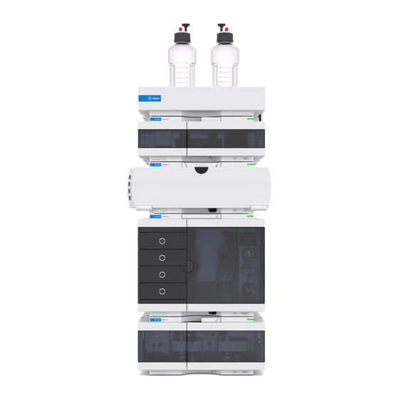
One Stack Configuration One Stack Configuration for Agilent 1260 Infinity LC Ensure optimum performance by installing the modules of the Agilent 1260 Infinity LC System in the following configuration (See Figure 8 on page 51 and Figure 9 on page 52). This configuration optimizes the flow path for minimum delay volume and minimizes the bench space required. - Page 51 Installing the Detector3 Figure 8 Recommended Stack Configuration for 1260 (Front View) Agilent 1260 Infinity Variable Wavelength Detector User Manual...
- Page 52 Installing the Detector Figure 9 Recommended Stack Configurationfor 1260 (Rear View) Agilent 1260 Infinity Variable Wavelength Detector User Manual...
-
Page 53: Two Stack Configuration
Installing the Detector3 Two Stack Configuration Two Stack Configuration for Agilent 1260 Infinity LC To avoid excessive height of the stack when the autosampler thermostat is added to the system it is recommended to form two stacks. Some users prefer the lower height of this arrangement even without the autosampler thermostat. - Page 54 Installing the Detector Figure 11 Recommended Two Stack Configuration for 1260 (Rear View) Agilent 1260 Infinity Variable Wavelength Detector User Manual...
-
Page 55: Installing The Detector
156. 2 Place the detector in the stack or on the bench in a horizontal position. 3 Ensure the line power switch at the front of the detector is OFF. Agilent 1260 Infinity Variable Wavelength Detector User Manual... - Page 56 58. 4 Connect the power cable to the power connector at the rear of the detector. 5 Connect the CAN cable to other Agilent 1260 Infinity modules. 6 If a Agilent ChemStation is the controller, connect the LAN connection to the LAN interface board in the detector.
- Page 57 OFF The detector was shipped with default configuration settings. To change these settings, N O T E “Setting the 8-bit Configuration Switch" on page 29. Agilent 1260 Infinity Variable Wavelength Detector User Manual...
-
Page 58: Flow Connections To The Detector
The flow cell is shipped with a filling of isopropanol (also recommended when the N O T E instrument and/or flow cell is shipped to another location). This is to avoid breakage due to subambient conditions. Agilent 1260 Infinity Variable Wavelength Detector User Manual... - Page 59 3 Assemble the column-detector capillary. 4 Connect the newly assembled fitting of the capillary to the Depending on the flow cell type it may be a PEEK or SST inlet connector. capillary. Agilent 1260 Infinity Variable Wavelength Detector User Manual...
- Page 60 The installation of the detector is now complete. The detector should be operated with the front cover in place to protect the flow cell area N O T E against strong drafts from the outside. Agilent 1260 Infinity Variable Wavelength Detector User Manual...
- Page 61 Agilent 1260 Infinity Series Variable Wavelength Detector User Manual Using the Detector Setting up an Analysis Before Using the System Requirements and Conditions Optimization of the System Preparing the HPLC System Running the Sample and Verifying the Results Special Settings of the Detector...
-
Page 62: Using The Detector
(when available in the system) and the pump. Solvents containing volatile ingredients will slightly lose these. Therefore priming of the pumping system is required before starting an application. Agilent 1260 Infinity Variable Wavelength Detector User Manual... - Page 63 2 Flush all tubes with at least 30 ml of solvent. 3 Set flow to required value of your application and close the purge valve. Pump for approximately 10 minutes before starting your application. Agilent 1260 Infinity Variable Wavelength Detector User Manual...
-
Page 64: Requirements And Conditions
Zorbax Eclipse XDB-C18, 4.6 x 150 mm, 5 um Part No. 993967-902 or Part No. 5063-6600 Standard: Part No. 01080-68704 0.15 wt.% dimethylphthalate, 0.15 wt.% diethylphthalate, 0.01 wt.% biphenyl, 0.03 wt.% o-terphenyl in methanol Agilent 1260 Infinity Variable Wavelength Detector User Manual... - Page 65 A single injection of the isocratic test standard is made under the conditions given in Table 19: Table 19 Conditions Flow 1.5 ml/minute Stoptime 8 minutes Solvent 100% (30% water/70% Acetonitrile) Temperature Ambient Wavelength 254 nm Injection Volume 1 µL Agilent 1260 Infinity Variable Wavelength Detector User Manual...
-
Page 66: Optimization Of The System
The settings used for this analysis are specific for this purpose. For other applications the system can be optimized in various ways. Please refer to the section “Optimizing the Detector" on page 85. Agilent 1260 Infinity Variable Wavelength Detector User Manual... -
Page 67: Preparing The Hplc System
Preparing the HPLC System 1 Turn on the Agilent ChemStation PC and the monitor. 2 Turn on the Agilent 1260 Infinity HPLC modules. 3 Start the Agilent ChemStation. If the pump, autosampler, thermostatted column compartment and detector are found, the ChemStation screen... - Page 68 On button or the buttons below the module icons on the graphical user interface (GUI). After some time, the pump, thermostatted column compartment and detector module will turn to green. Figure 16 Turning on the HPLC Module Agilent 1260 Infinity Variable Wavelength Detector User Manual...
- Page 69 For reproducible chromatography, the detector and lamp should be on for at least one hour. N O T E Otherwise the detector baseline may still drift (depending on the environment). Figure 17 Stabilization of Baseline Agilent 1260 Infinity Variable Wavelength Detector User Manual...
- Page 70 8 Click on the Load Method button and select and press OK. Alternative double-click on the method in the method window. The default LC method parameters are transferred into the modules. Figure 18 Loading Default LC Method Agilent 1260 Infinity Variable Wavelength Detector User Manual...
- Page 71 72 shows the detector settings (do not change the detector parameters at this time). Figure 19 Open the module menu 10 Enter the pump parameters mentioned under “Conditions" on page 65. Agilent 1260 Infinity Variable Wavelength Detector User Manual...
- Page 72 (for diagnostics) • autobalance to zero absorbance (on the analog output plus offset) at begin and/or end of run • see “Special Setpoints" on page 82 Figure 20 Detector Settings (default) Agilent 1260 Infinity Variable Wavelength Detector User Manual...
- Page 73 Change the Y-range for the VWD to 1 mAU and the offset to 20% and the pressure offset to 50%. The X-axis range should be 15 minutes. Press OK to exit this screen. Figure 21 Edit Signal Plot Window Agilent 1260 Infinity Variable Wavelength Detector User Manual...
- Page 74 13 If both baselines are stable, set the Y-range for the detector signal to 100 mAU. If you start with a new UV-lamp for the first time, the lamp may show initial drift for some N O T E time (burn-in effect). Agilent 1260 Infinity Variable Wavelength Detector User Manual...
- Page 75 Figure 23 Sample Information 15 Fill the content of an isocratic standard sample ampoule into a vial and seal the vial with a cap and place the vial into autosampler tray (position #1). Agilent 1260 Infinity Variable Wavelength Detector User Manual...
-
Page 76: Running The Sample And Verifying The Results
Figure 24 Chromatogram with Isocratic Test Sample Information about using the Data Analysis functions can be obtained from the Using your N O T E ChemStation manual supplied with your system. Agilent 1260 Infinity Variable Wavelength Detector User Manual... -
Page 77: Special Settings Of The Detector
2140-0590 (DAD lamps), see also “Exchanging a Lamp" on page 142. • Automatic Turn On: lamps can be programmed (detector must be on for this). • Help: online help. Figure 25 Detector control settings Agilent 1260 Infinity Variable Wavelength Detector User Manual... -
Page 78: Online Spectra
This online spectrum is taken during a stop-flow condition only while the peak is kept in the N O T E flow cell, see “Scanning with the VWD" on page 79. Figure 26 Online Spectra Window 2 Change the absorbance and wavelength range according your needs. Agilent 1260 Infinity Variable Wavelength Detector User Manual... -
Page 79: Scanning With The Vwd
Turning off the pump would stop the run and no access to the sample scan is possible. N O T E Agilent 1260 Infinity Variable Wavelength Detector User Manual... - Page 80 A sample scan is taken in the range defined under “Special Setpoints" page 82 and the Online Spectra window (see “Online Spectra" on page 78) displays the result (Sample Scan minus Blank Scan). Agilent 1260 Infinity Variable Wavelength Detector User Manual...
-
Page 81: Analog Output Settings
100 mV or 1 V full scale. • Attenuation Limits: 0.98 to 4000 mAU at discrete values for either 100 mV or 1 V full scale. Figure 28 Analog Output Settings 3 Change the values if required. Agilent 1260 Infinity Variable Wavelength Detector User Manual... -
Page 82: Special Setpoints
Spectra Window Margin for negative Absorbance: The higher the value the greater the baseline noise. Set N O T E this value only if you expect negative absorbance greater than -100 mAU. Agilent 1260 Infinity Variable Wavelength Detector User Manual... -
Page 83: Peakwidth Settings
Limits: When you set the peak width (in minutes), the corresponding response time is set automatically and the appropriate data rate for signal acquisition is selected as shown in Table 20 on page 84. Figure 30 Peakwidth Setting Agilent 1260 Infinity Variable Wavelength Detector User Manual... - Page 84 <0.031 >0.00125 0.031 27.5 >0.0025 0.062 13.74 >0.005 0.12 13.74 >0.01 0.25 13.74 >0.025 13.74 >0.05 6.87 >0.10 3.43 >0.20 1.72 >0.40 0.86 * Values in the User Interface may be rounded. Agilent 1260 Infinity Variable Wavelength Detector User Manual...
-
Page 85: Optimizing The Detector
Using the Detector4 Optimizing the Detector Additional theoretical information can be found in chapter “How to optimize the detector" on page 87. Agilent 1260 Infinity Variable Wavelength Detector User Manual... - Page 86 Using the Detector Agilent 1260 Infinity Variable Wavelength Detector User Manual...
-
Page 87: How To Optimize The Detector
Agilent 1260 Infinity Series Variable Wavelength Detector User Manual How to optimize the detector Optimizing the Detector Performance This chapter gives hints on how to select the detector parameters and the flow cell. Agilent Technologies... -
Page 88: Optimizing The Detector Performance
0.05 – 0.2 ml/min 0.2 – 0.4 ml/min 0.4 – 0.8 ml/min 1 – 2 ml/min Internal column diameter 1.0 mm 2.1 mm 3.0 mm 4.6 mm Figure 31 Choosing a Flow Cell Agilent 1260 Infinity Variable Wavelength Detector User Manual... - Page 89 To determine the volume of your peaks, take the peak width as reported in the integration results multiply it by the flow rate and divide it by 3). Agilent 1260 Infinity Variable Wavelength Detector User Manual...
- Page 90 Traditionally LC analysis with UV detectors is based on comparing measurements with internal or external standards. To check photometric accuracy of the Agilent 1260 Infinity VWD it is necessary to have more precise information on path lengths of the VWD flow cells.
-
Page 91: Set The Detector Parameters
• at a wavelength with moderate absorptivity if you work with high concentrations, and • preferably where the spectrum is flat for better linearity. 3 Consider to use time-programming to further optimization. Agilent 1260 Infinity Variable Wavelength Detector User Manual... - Page 92 How to optimize the detector Agilent 1260 Infinity Variable Wavelength Detector User Manual...
-
Page 93: Troubleshooting And Diagnostics
Agilent 1260 Infinity Series Variable Wavelength Detector User Manual Troubleshooting and Diagnostics Overview of the Detector’s Indicators and Test Functions Status Indicators Available Tests vs User Interfaces Agilent LabAdvisor Software Overview about the troubleshooting and diagnostic features. Agilent Technologies... -
Page 94: Overview Of The Detector's Indicators And Test Functions
Diagnostic Signals The detector has several signals (internal temperatures, voltages and currents of lamps) that can be used for diagnosing baseline problems. Agilent 1260 Infinity Variable Wavelength Detector User Manual... -
Page 95: Status Indicators
Figure 33 Location of Status Indicators Power Supply Indicator The power supply indicator is integrated into the main power switch. When the indicator is illuminated (green) the power is ON. Agilent 1260 Infinity Variable Wavelength Detector User Manual... -
Page 96: Module Status Indicator
(modules without on-board LAN) indicator indicates that the module is in boot loader mode (e.g. during update of main firmware). In such a case try to re-boot the module or try a cold-start. Agilent 1260 Infinity Variable Wavelength Detector User Manual... -
Page 97: Available Tests Vs User Interfaces
(see Chapter "Test Functions and Calibrations"). • Preferred tool should be the Agilent Diagnostic Software, see “Agilent Lab Advisor Software” on page 156. • Screenshots used within these procedures are based on the Agilent Lab Advisor Software. Agilent 1260 Infinity Variable Wavelength Detector User Manual... -
Page 98: Agilent Labadvisor Software
Agilent Lab Advisor software may differ from the descriptions in this manual. For details refer to the Agilent Lab Advisor software help files. This manual provides lists with the names of Error Messages, Not Ready messages, and other common issues. Agilent 1260 Infinity Variable Wavelength Detector User Manual... -
Page 99: Error Information
Agilent 1260 Infinity Series Variable Wavelength Detector User Manual Error Information What Are Error Messages General Error Messages Detector Error Messages This chapter describes the meaning of detector error messages, and provides information on probable causes and suggested actions how to recover from error conditions. -
Page 100: What Are Error Messages
In the event of such a failure, the red status indicator at the front of the module is switched on, and an entry is written into the instrument logbook. Agilent 1260 Infinity Variable Wavelength Detector User Manual... -
Page 101: General Error Messages
2 A not-ready condition was present during a Check the logbook for the occurrence and sequence or multiple-injection run for a source of a not-ready condition. period longer than the timeout threshold. Agilent 1260 Infinity Variable Wavelength Detector User Manual... -
Page 102: Shut-Down
2 Defective remote cable. Exchange the remote cable. 3 Defective components in the instrument Check the instrument for defects (refer to the showing the not-ready condition. instrument’s documentation). Agilent 1260 Infinity Variable Wavelength Detector User Manual... -
Page 103: Synchronization Lost
VWM board. Probable cause Suggested actions 1 Loose fittings. Ensure all fittings are tight. 2 Broken capillary. Exchange defective capillaries. 3 Leaking flow cell. Exchange flow cell components. Agilent 1260 Infinity Variable Wavelength Detector User Manual... -
Page 104: Leak Sensor Open
If the current increases above the upper limit, the error message is generated. Probable cause Suggested actions 1 Defective leak sensor. Exchange the leak sensor. Agilent 1260 Infinity Variable Wavelength Detector User Manual... -
Page 105: Compensation Sensor Open
If the resistance across the sensor falls below the lower limit, the error message is generated. Probable cause Suggested actions 1 Defective VWM board Exchange the main board. Agilent 1260 Infinity Variable Wavelength Detector User Manual... -
Page 106: Fan Failed
The sensor on the VWM board detects when the top foam is in place. If the foam is removed during operation, the lamp and grating drive power is switched off, and the error message is generated. Probable cause Suggested actions 1 Top foam removed. Replace the foam. Agilent 1260 Infinity Variable Wavelength Detector User Manual... -
Page 107: Detector Error Messages
Probable cause Suggested actions 1 Defective or non-Agilent lamp. Exchange the lamp. 2 Defective power supply. Exchange the power supply. 3 Defective VWM board Exchange the VWM board. Agilent 1260 Infinity Variable Wavelength Detector User Manual... -
Page 108: Lamp Ignition Failed
Replace the top foam, and turn on the lamp. place. 3 Defective VWM board Exchange the VWM board. 4 Defective or non-Agilent lamp. Exchange the lamp. 5 Defective power supply. Exchange the power supply. Agilent 1260 Infinity Variable Wavelength Detector User Manual... -
Page 109: Calibration Failed
Repeat the calibration. 6 Misaligned/defective grating assembly. Run the grating-motor test to determine if the grating assembly is defective. If defective, replace the optical unit. 7 ProbableCause? Exchange the VWM board. Agilent 1260 Infinity Variable Wavelength Detector User Manual... -
Page 110: Holmium Oxide Test Failed
If the end position is not found, the error message is generated. Probable cause Suggested actions 1 Defective motor assembly. Run the grating-motor test to determine if the grating assembly is defective. If defective, replace the optical unit. Agilent 1260 Infinity Variable Wavelength Detector User Manual... -
Page 111: Wavelength Check Failed
Probable cause Suggested actions 1 Filter motor defective. Run the filter motor test to determine if the motor is defective. 2 Defective or missing filter. Exchange the filter assembly. Agilent 1260 Infinity Variable Wavelength Detector User Manual... - Page 112 Error Information Agilent 1260 Infinity Variable Wavelength Detector User Manual...
-
Page 113: Test Functions
Agilent 1260 Infinity Series Variable Wavelength Detector User Manual Test Functions Available Tests versus Interfaces Intensity Test Checking the Photocurrent Wavelength Verification/Calibration ASTM Drift and Noise Test Quick Noise Test Dark Current Test Holmium Oxide Test D/A Converter (DAC)Test Grating and Filter Motor Test Test Chromatogram This chapter describes the detector’s built in test functions. -
Page 114: Available Tests Versus Interfaces
Tests (*) Tests (*) Filter / Grating Motor Test Tests (*) Tests (*) Test Chromatogram Tools from command line Spectrum (Blank, Sample, Holmium) Tools (*) interface provides passed/fail information or a plot. Agilent 1260 Infinity Variable Wavelength Detector User Manual... -
Page 115: Intensity Test
The Agilent Lab Advisor and the Instant Pilot evaluate three values automatically and display the limits for each value, the average, the minimum and the maximum of all data points and passed or failed for each value. Agilent 1260 Infinity Variable Wavelength Detector User Manual... - Page 116 2 Flow cell windows dirty Repeat the test with the flow cell removed. If the test passes, exchange the flow cell windows. 3 Optics defect Clean/replace optical components. 4 Defective lamp or optics. Exchange the lamp. Agilent 1260 Infinity Variable Wavelength Detector User Manual...
-
Page 117: Checking The Photocurrent
• dirty windows, • absorbing solvents/compounds, • not correctly mounted flow cell, or • air bubbles Agilent 1260 Infinity Variable Wavelength Detector User Manual... -
Page 118: Wavelength Verification/Calibration
These holmium lines are at 360.8 nm, 418.5 nm and 536.4 nm. This function is available in • Agilent LabAdvisior (preferred) • Agilent ChemStation • Instant Pilot (G4208A) Figure 36 Wavelength Verification/Calibration (Agilent ChemStation) Agilent 1260 Infinity Variable Wavelength Detector User Manual... - Page 119 656 nm emission line of the deuterium lamp. The detector searches for maximum light intensity in the region of the 656 nm emission line. The 656 nm calibration values are stored in the instrument. Agilent 1260 Infinity Variable Wavelength Detector User Manual...
- Page 120 The result should be value 2 < value 1/16. If not OK, the cutoff filter does not work correctly. • Restore the set wavelength position. • The detector should now be ready condition. Agilent 1260 Infinity Variable Wavelength Detector User Manual...
- Page 121 Test Functions Wavelength Verification/Calibration with Agilent LabAdvisor Figure 37 Wavelength Verification and Calibration (Agilent LabAdvisor) Agilent 1260 Infinity Variable Wavelength Detector User Manual...
-
Page 122: Astm Drift And Noise Test
20 minutes. The test is done with HPLC-grade water flowing through the flow cell at 1 mL/min. On completion of the test, the noise result is displayed automatically. Figure 38 ASTM Drift and Noise Test (Agilent LabAdvisor) Agilent 1260 Infinity Variable Wavelength Detector User Manual... -
Page 123: Quick Noise Test
The cycles in the noise determination are not overlapping. In order to obtain reliable results, the lamp should be turned on for at least 10 minutes prior to measurement. Figure 39 Quick Noise Test (Agilent LabAdvisor) Agilent 1260 Infinity Variable Wavelength Detector User Manual... -
Page 124: Dark Current Test
Dark Current Test Failed Probable Causes Suggested Actions 1 Defective sample or reference diode. Exchange optical unit. 2 Defective sample or reference VWA board. Exchange optical unit. 3 Defective VWM board. Exchange the VWM board. Agilent 1260 Infinity Variable Wavelength Detector User Manual... - Page 125 Test Functions Dark Current Test with Agilent LabAdvisor. Figure 40 Dark Current Test (Agilent LabAdvisor) Agilent 1260 Infinity Variable Wavelength Detector User Manual...
-
Page 126: Holmium Oxide Test
ChemStation revisions below B.01.xx show a limit of ± 2 nm. It should read ± 1 nm. If the N O T E test shows a value greater than ± 1 nm, perform a recalibration. Agilent 1260 Infinity Variable Wavelength Detector User Manual... - Page 127 OK, exchange the flow cell components. 3 Dirty or defective holmium oxide filter. Run the holmium oxide filter test. If the test fails, exchange the filter assembly. 4 Optical misalignment. Replace the optical unit. Agilent 1260 Infinity Variable Wavelength Detector User Manual...
-
Page 128: D/A Converter (Dac)Test
When to do the Test • if the detector signal is noisy or missing. Running the test with Agilent LabAdvisor 1 Run the D/A Converter (DAC) Test (for further information see Online-Help of user interface). Agilent 1260 Infinity Variable Wavelength Detector User Manual... - Page 129 Test Functions Figure 42 D/C Test with Agilent LabAdvisor 2 Observe the analog output signal. Figure 43 D/A Converter (DAC) Test – Example of Integrator Plot Agilent 1260 Infinity Variable Wavelength Detector User Manual...
- Page 130 The noise on the step should be less than 3 µV. Probable cause Suggested actions 1 Bad cable or grounding problem between Check or replace the cable. detector and external device. 2 Defective detector main board. Exchange the detector main board. Agilent 1260 Infinity Variable Wavelength Detector User Manual...
-
Page 131: Grating And Filter Motor Test
When to do the Test • if recalibration cannot be done successfully, or • if the holmium test fails. Filter/Grating Motor Test with Agilent LabAdvisor Figure 44 Grating and Filter Motor Test with Agilent LabAdvisor Agilent 1260 Infinity Variable Wavelength Detector User Manual... - Page 132 Exchange the VWM board Filter Motor Test Failed Probable cause Suggested actions 1 Defective filter motor Exchange Optical Unit. 2 Defective filter position sensor Exchange Optical Unit. 3 Defective VWM board Exchange the VWM board Agilent 1260 Infinity Variable Wavelength Detector User Manual...
-
Page 133: Test Chromatogram
4 Turn the Test Chromatogram on. 5 Change to the detector's Module Service Center and add the detector signal to the Signal Plot window. 6 To start a test chromatogram enter in the command line: STRT Agilent 1260 Infinity Variable Wavelength Detector User Manual... - Page 134 Test Chromatogram with Agilent LabAdvisor 7 To stop the test chromatogram enter in the command line: STOP The test chromatogram is switched off automatically at the end of a run. N O T E Agilent 1260 Infinity Variable Wavelength Detector User Manual...
-
Page 135: Maintenance And Repair
Agilent 1260 Infinity Series Variable Wavelength Detector User Manual Maintenance and Repair Introduction to Maintenance Warnings and Cautions This chapter provides general information on maintenance and repair of the detector. Agilent Technologies... -
Page 136: Introduction To Maintenance
The module is designed for easy repair. The most frequent repairs such as lamp change and flow cell change can be done from the front with the module in place in the system stack. Agilent 1260 Infinity Variable Wavelength Detector User Manual... -
Page 137: Warnings And Cautions
→ The amount of substances should be reduced to the minimal volume required for the analysis. → Do not operate the instrument in an explosive atmosphere. Agilent 1260 Infinity Variable Wavelength Detector User Manual... - Page 138 → If you connect external equipment to the instrument, make sure that you only use accessory units tested and approved according to the safety standards appropriate for the type of external equipment. Agilent 1260 Infinity Variable Wavelength Detector User Manual...
- Page 139 Agilent 1260 Infinity Series Variable Wavelength Detector User Manual Maintenance Overview of Maintenance Cleaning the Module Exchanging a Lamp Exchanging a Flow Cell Repairing the Flow Cells Using the Cuvette Holder Correcting Leaks Replacing Leak Handling System Parts Replacing the Interface Board Replacing the Detector’s Firmware...
-
Page 140: Maintenance
A pressure tightness test should be cleaning or exchange cell windows. done after repair. Leak sensor drying If leak has occurred. Check for leaks. Leak handling system If broken or corroded. Check for leaks. replacement Agilent 1260 Infinity Variable Wavelength Detector User Manual... -
Page 141: Cleaning The Module
Liquid in the module electronics can cause shock hazard and damage the module. → Do not use an excessively damp cloth during cleaning. → Drain all solvent lines before opening any fittings. Agilent 1260 Infinity Variable Wavelength Detector User Manual... -
Page 142: Exchanging A Lamp
Injury by touching hot lamp WA R N I N G If the detector has been in use, the lamp may be hot. → If so, wait for lamp to cool down. Agilent 1260 Infinity Variable Wavelength Detector User Manual... - Page 143 1 Press the release buttons and remove the front cover to have access to the lamp area. • Turn the lamp OFF. Unscrew the lamp cover and remove it. Unscrew, disconnect and replace the lamp. Insert, fix and reconnect the lamp. Agilent 1260 Infinity Variable Wavelength Detector User Manual...
- Page 144 Reset the lamp counter as described in the User Interface documentation. • Turn the lamp ON. • Give the lamp more than 10 minutes to warm-up. • Perform “Wavelength Verification/Calibration" on page 118 to check the correct positioning of the lamp. Agilent 1260 Infinity Variable Wavelength Detector User Manual...
-
Page 145: Exchanging A Flow Cell
High pressure flow cell, 10 mm, 14 µL, 400 bar, G1314-60082 Preparations for this procedure: Press the release buttons and remove the front cover to have access to the flow cell area. • Turn the lamp OFF. Agilent 1260 Infinity Variable Wavelength Detector User Manual... - Page 146 If you want to maintain flow cell parts, see “Repairing the Flow Cells" on page 148 or the information provided with your flow cell. Agilent 1260 Infinity Variable Wavelength Detector User Manual...
- Page 147 (outside of the cell compartment) and all capillary connections. • Insert the flow cell. • Perform “Wavelength Verification/Calibration" page 118 to check the correct positioning of the flow cell. • Replace the front cover. Agilent 1260 Infinity Variable Wavelength Detector User Manual...
-
Page 148: Repairing The Flow Cells
“Exchanging a Flow Cell" on page 145. The shown cell parts will differ depending upon the flow cell type. For detailed parts N O T E schematics, refer to above mentioned pages. Agilent 1260 Infinity Variable Wavelength Detector User Manual... - Page 149 5 Pour isopropanol into the cell hole and wipe clean with a piece of lint-free Cell Parts cloth. 6 Clean the windows with ethanol or methanol. Dry it with a piece of lint-free cloth. Always use new gaskets. N O T E Agilent 1260 Infinity Variable Wavelength Detector User Manual...
- Page 150 • Perform a leak test. If OK, insert the flow cell. • Perform “Wavelength Verification/Calibration" on page 118 to check the correct positioning of the flow cell. • Replace the front cover. Agilent 1260 Infinity Variable Wavelength Detector User Manual...
-
Page 151: Using The Cuvette Holder
Standard cuvettes with standards in it, for example, National Institute of Standards & Technology (NIST) holmium oxide solution standard, can be fixed in it. This can be used for wavelength verifications. Figure 47 Cuvette Holder Agilent 1260 Infinity Variable Wavelength Detector User Manual... - Page 152 Reset the lamp counter as described in the User Interface documentation. • Turn the lamp ON. • Give the lamp more than 10 minutes to warm-up. • Perform “Wavelength Verification/Calibration" on page 118 to check the correct positioning of the lamp. Agilent 1260 Infinity Variable Wavelength Detector User Manual...
- Page 153 Maintenance Install the cuvette holder in the instrument. Replace the bracket and fix the cuvette. Next steps: • Perform your verification. Agilent 1260 Infinity Variable Wavelength Detector User Manual...
-
Page 154: Correcting Leaks
3 Observe the capillary connections and the flow cell area for leaks and correct, if required. 4 Replace the front cover. Leak plane Waste outlet Leak sensor assembly Figure 48 Drying the Leak Sensor Agilent 1260 Infinity Variable Wavelength Detector User Manual... -
Page 155: Replacing Leak Handling System Parts
6 Insert the leak funnel into the leak funnel holder. 7 Replace the front cover. Leak funnel holder Leak funnel Leak tubing Leak plan Waste outlet Leak sensor assembly Figure 49 Replacing Waste Handling System Parts Agilent 1260 Infinity Variable Wavelength Detector User Manual... -
Page 156: Replacing The Interface Board
ESD kit. ESD strap power lock If required, insert the interface board and fix the screws. Next steps: • Remove the ESD strap. • Reinstall the module into the stack. Agilent 1260 Infinity Variable Wavelength Detector User Manual... -
Page 157: Replacing The Detector's Firmware
1 Download the required module firmware, the latest LAN/RS-232 FW Update Tool and the documentation from the Agilent web. • http://www.chem.agilent.com/scripts/cag_firmware.asp. 2 To load the firmware into the module follow the instructions in the documentation. Agilent 1260 Infinity Variable Wavelength Detector User Manual... - Page 158 Initial firmware A.06.02 A.06.02 Compatibility with 1100 / 1200 series yes, all modules should have the firmware from the modules same set. Conversion to / emulation of G1314A or possible, if required G1314B Agilent 1260 Infinity Variable Wavelength Detector User Manual...
-
Page 159: Parts And Materials For Maintenance
Agilent 1260 Infinity Series Variable Wavelength Detector User Manual Parts and Materials for Maintenance Overview of Maintenance Parts Standard Flow Cell Micro Flow Cell Semi-micro Flow Cell High Pressure Flow Cell Cuvette Holder Leak Parts Accessory Kit This chapter provides information on parts for maintenance. -
Page 160: Overview Of Maintenance Parts
High pressure flow cell, 10 mm 14 µL, additional flow cell parts, see page 165 G1314-60082 Semi-micro flow cell, 6 mm 5 µL, additional flow cell parts, see page 163 G1314-60083 Cuvette Holder G1314-60200 Front cover 5067-4691 Leak handling parts page 167 Agilent 1260 Infinity Variable Wavelength Detector User Manual... -
Page 161: Standard Flow Cell
2 - Conical Springs 3 - Ring #1 PEEK 4 - Gasket #1 (small hole) 5 - Window Quartz 6 - Gasket #2 (large hole) 7 - Ring #2 PEEK Figure 50 Standard Flow Cell Agilent 1260 Infinity Variable Wavelength Detector User Manual... -
Page 162: Micro Flow Cell
Gasket #2, PTFE, quantity=10 G1314-65053 1 - Cell Screw 2 - Conical Springs 3 - Ring SST 4 - Gasket #1 5 - Window Quartz 6 - Gasket #2 Figure 51 Micro Flow Cell Agilent 1260 Infinity Variable Wavelength Detector User Manual... -
Page 163: Micro Flow Cell
G1314-65058 Inlet capillary, 400 mm long, 0.12 mm i.d. 5021-1823 The semi-micro #1 and #2 gaskets (items 6 and 7) look very similar. Do not mix them up N O T E Agilent 1260 Infinity Variable Wavelength Detector User Manual... -
Page 164: Semi-Micro Flow Cell
1 - Cell screw 2 - Conical springs 3 - Ring SST 4 - Gasket #1 5 - Quartz window 6 - Semi-micro gasket #1 7 - Semi-micro gasket #2 Figure 52 Semi-micro Flow Cell Agilent 1260 Infinity Variable Wavelength Detector User Manual... -
Page 165: High Pressure Flow Cell
79853-68734 Gasket kit, KAPTON, quantity=10 G1314-65055 1 - Cell screw 2 - Ring PEEK 3 - Window quartz 4 - Gasket KAPTON 5 - Cell Cover Figure 53 High Pressure Flow Cell Agilent 1260 Infinity Variable Wavelength Detector User Manual... -
Page 166: Cuvette Holder
Table 32 Cuvette Holder Item Description Part Number Cuvette Holder G1314-60200 For information the use of the cuvette holder, refer to “Using the Cuvette Holder" on page 151. Figure 54 Cuvette Holder Agilent 1260 Infinity Variable Wavelength Detector User Manual... -
Page 167: Leak Parts
Table 33 Leak Parts Item Description Part Number Leak funnel 5041-8388 Leak funnel holder 5041-8389 Clip 5041-8387 6, 7 Corrugated tubing, 1200 mm lg, re-order 5 m 5062-2463 Figure 55 Leak Parts Agilent 1260 Infinity Variable Wavelength Detector User Manual... -
Page 168: Accessory Kit
Accessory Kit Parts Description Part Number Accessory kit G1314-68755 Corrugated tubing (to waste), re-order 5 m 5062-2463 Peek outlet capillary kit, i.d. is 0.25 mm (PEEK) 5062-8535 Fitting male PEEK 2/pk 0100-1516 Agilent 1260 Infinity Variable Wavelength Detector User Manual... - Page 169 Agilent 1260 Infinity Series Variable Wavelength Detector User Manual Identifying Cables Cable Overview Analog Cables Remote Cables BCD Cables CAN / LAN Cables RS-232 Cable External Contact Cable This chapter provides information on cables used with the Agilent 1260 Infinity modules.
- Page 170 Identifying Cables Cable Overview Never use cables other than the ones supplied by Agilent Technologies to ensure proper N O T E functionality and compliance with safety or EMC regulations. Analog cables Description 35900-60750 Agilent module to 3394/6 integrators 35900-60750...
- Page 171 It's also called "Null Modem Cable" with full handshaking where the wiring is made between pins 1-1, 2-3, 3-2, 4-6, 5-5, 6-4, 7-8, 8-7, 9-9. 5181-1561 RS-232 cable, 8 m Agilent 1260 Infinity Variable Wavelength Detector User Manual...
- Page 172 Identifying Cables Analog Cables One end of these cables provides a BNC connector to be connected to Agilent 1260 Infinity modules. The other end depends on the instrument to which connection is being made. Agilent Module to 3394/6 Integrators 35900-60750...
- Page 173 Identifying Cables Agilent Module to General Purpose 01046-60105 Signal name 3394/6 Agilent module Not connected Black Analog - Analog + Agilent 1260 Infinity Variable Wavelength Detector User Manual...
- Page 174 Remote Cables One end of these cables provides a Agilent Technologies APG (Analytical Products Group) remote connector to be connected to Agilent 1260 Infinity modules. The other end depends on the instrument to be connected to. Agilent Module to 3396A Integrators...
- Page 175 6 - Yellow 6 - Yellow Power on High 7 - Red 7 - Red Ready High 8 - Green 8 - Green Stop 9 - Black 9 - Black Start request Agilent 1260 Infinity Variable Wavelength Detector User Manual...
- Page 176 3 - Gray Start 4 - Blue Shut down 5 - Pink Not connected 6 - Yellow Power on High 7 - Red Ready High 8 - Green Stop 9 - Black Start request Agilent 1260 Infinity Variable Wavelength Detector User Manual...
- Page 177 Identifying Cables BCD Cables One end of these cables provides a 15-pin BCD connector to be connected to the Agilent 1260 Infinity modules. The other end depends on the instrument to be connected to Agilent Module to General Purpose G1351-81600...
- Page 178 Agilent Module to 3396 Integrators 03396-60560 Signal name BCD Digit 3392/3 Agilent module BCD 5 BCD 7 BCD 6 BCD 4 BCD0 BCD 3 BCD 2 BCD 1 Digital ground + 5 V Agilent 1260 Infinity Variable Wavelength Detector User Manual...
- Page 179 CAN cable, Agilent module to module, 1 m LAN Cables Description 5023-0203 Cross-over network cable, shielded, 3 m (for point to point connection) 5023-0202 Twisted pair network cable, shielded, 7 m (for point to point connection) Agilent 1260 Infinity Variable Wavelength Detector User Manual...
- Page 180 It's also called "Null Modem Cable" with full handshaking where the wiring is made between pins 1-1, 2-3, 3-2, 4-6, 5-5, 6-4, 7-8, 8-7, 9-9. 5181-1561 RS-232 cable, 8 m Agilent 1260 Infinity Variable Wavelength Detector User Manual...
- Page 181 External Contact Cable One end of this cable provides a 15-pin plug to be connected to Agilent 1260 Infinity module’s interface board. The other end is for general purpose. Agilent 1260 Infinity Interface Board to general purposes G1103-61611 Color Signal Name...
- Page 182 Identifying Cables Agilent 1260 Infinity Variable Wavelength Detector User Manual...
-
Page 183: A Appendix
Agilent 1260 Infinity Series Variable Wavelength Detector User Manual Appendix General Safety Information Lithium Batteries Information Radio Interference Sound Emission UV-Radiation Solvent Information Declaration of Conformity for HOX2 Filter Agilent Technologies on Internet This chapter provides addition information on safety, legal and web. -
Page 184: General Safety Information
Whenever it is likely that the protection has been impaired, the instrument must be made inoperative and be secured against any intended operation. Agilent 1260 Infinity Variable Wavelength Detector User Manual... -
Page 185: A Appendix
When working with solvents please observe appropriate safety procedures (e.g. goggles, safety gloves and protective clothing) as described in the material handling and safety data sheet by the solvent vendor, especially when toxic or hazardous solvents are used. Agilent 1260 Infinity Variable Wavelength Detector User Manual... - Page 186 C A U T I O N alerts you to situations that could cause loss of data, or damage of equipment. → Do not proceed beyond a caution until you have fully understood and met the indicated conditions. Agilent 1260 Infinity Variable Wavelength Detector User Manual...
-
Page 187: Lithium Batteries Information
WA R N I N G av apparatfabrikanten. Brukt batteri returneres appararleverandoren. Bij dit apparaat zijn batterijen geleverd. Wanneer deze leeg zijn, moet u ze niet weggooien N O T E maar inleveren als KCA. Agilent 1260 Infinity Variable Wavelength Detector User Manual... -
Page 188: Radio Interference
If test and measurement equipment is operated with unscreened cables, or used for measurements on open set-ups, the user has to assure that under operating conditions the radio interference limits are still met within the premises. Agilent 1260 Infinity Variable Wavelength Detector User Manual... -
Page 189: Sound Emission
This product has a sound pressure emission (at the operator position) < 70 dB. • Sound Pressure Lp < 70 dB (A) • At Operator Position • Normal Operation • According to ISO 7779:1988/EN 27779/1991 (Type Test) Agilent 1260 Infinity Variable Wavelength Detector User Manual... -
Page 190: Uv-Radiation
Typically the radiation values are much smaller than these limits: Table 37 UV-Radiation Typical Values Position Effective Irradiance Lamp installed, 50-cm distance average 0.016 µW/cm Lamp installed, 50-cm distance maximum 0.14 µW/cm Agilent 1260 Infinity Variable Wavelength Detector User Manual... -
Page 191: Solvent Information
• Halogenated solvents or mixtures which form radicals and/or acids, for example: → 2CHCl 2COCl + 2HCl This reaction, in which stainless steel probably acts as a catalyst, occurs quickly with dried chloroform if the drying process removes the stabilizing alcohol. Agilent 1260 Infinity Variable Wavelength Detector User Manual... - Page 192 For example, a 1-% solution of acetic acid in methanol will attack steel. • Solutions containing strong complexing agents (for example, EDTA, ethylene diamine tetra-acetic acid). • Mixtures of carbon tetrachloride with 2-propanol or THF. Agilent 1260 Infinity Variable Wavelength Detector User Manual...
-
Page 193: Declaration Of Conformity For Hox2 Filter
Appendix Declaration of Conformity for HOX2 Filter Agilent 1260 Infinity Variable Wavelength Detector User Manual... -
Page 194: Agilent Technologies On Internet
For the latest information on products and services visit our worldwide web site on the Internet at: http://www.agilent.com Select “Products” - “Chemical Analysis” It will provide also the latest firmware of the Agilent 1260 Infinity modules for download. Agilent 1260 Infinity Variable Wavelength Detector User Manual... - Page 195 94, connecting the APG remote, calibration failed, connecting the CAN, compensation sensor open, connecting the ChemStation, compensation sensor short, general error messages, connecting the LAN, detector, GPIB Agilent 1260 Infinity Variable Wavelength Detector Service Manual...
- Page 196 (parts), mirror APG remote, line assemblies, BCD, power consumption, CAN, voltage and frequency, external contact, linearity, 43, overview, parts for maintenance Agilent 1260 Infinity Variable Wavelength Detector Service Manual...
- Page 197 ’maintenance’, stable baseline, at power on, replacing stack configuration, 50, attenuation, firmware, rear view, autobalance, response time, 84, standards, automatic turn on, status indicators, 94, data rate, Agilent 1260 Infinity Variable Wavelength Detector Service Manual...
- Page 198 UV-radiation, warm up, warnings and cautions, wavelength accuracy, calibration, range 190-600 nm, Agilent 1260 Infinity Variable Wavelength Detector Service Manual...
- Page 200 In This Book This manual contains the technical reference information about the Agilent 1260 Infinity Variable Wavelength Detector. The manual describes the following: • introcduction and specifications, • installation, • using and optimizing, • troubleshooting and diagnose, • maintenance, •...