Endress+Hauser Proline Promag W 400 Manuals
Manuals and User Guides for Endress+Hauser Proline Promag W 400. We have 6 Endress+Hauser Proline Promag W 400 manuals available for free PDF download: Operating Instructions Manual, Technical Information, Brief Operating Instructions
Endress+Hauser Proline Promag W 400 Operating Instructions Manual (186 pages)
EtherNet/IP
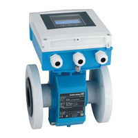
Electromagnetic flowmeter
Brand: Endress+Hauser
|
Category: Measuring Instruments
|
Size: 4.63 MB
Table of Contents
Advertisement

Endress+Hauser Proline Promag W 400 Operating Instructions Manual (168 pages)
Electromagnetic flowmeter
Brand: Endress+Hauser
|
Category: Measuring Instruments
|
Size: 4.09 MB
Table of Contents
Endress+Hauser Proline Promag W 400 Technical Information (92 pages)
Electromagnetic flowmeter
Brand: Endress+Hauser
|
Category: Measuring Instruments
|
Size: 3.44 MB
Table of Contents
Advertisement

Endress+Hauser Proline Promag W 400 Brief Operating Instructions (64 pages)
Electromagnetic flowmeter
Brand: Endress+Hauser
|
Category: Measuring Instruments
|
Size: 1.99 MB
Table of Contents

Endress+Hauser Proline Promag W 400 Brief Operating Instructions (64 pages)
Electromagnetic flowmeter
Brand: Endress+Hauser
|
Category: Measuring Instruments
|
Size: 3.24 MB
Table of Contents

Endress+Hauser Proline Promag W 400 Brief Operating Instructions (56 pages)
transmitter with electromagnetic sensor
Brand: Endress+Hauser
|
Category: Transmitter
|
Size: 4.55 MB
Table of Contents
Advertisement
Related Products
- Endress+Hauser Proline Promag W 400 HART
- Endress+Hauser Proline Promag W 500
- Endress+Hauser Proline Promag W 800
- Endress+Hauser Cleanfit W CPA450
- Endress+Hauser Proline Promag W 300 PROFINET
- Endress+Hauser PROline promag 50 w
- Endress+Hauser PROline promag 53 W
- Endress+Hauser Proline Promag L 400
- Endress+Hauser Proline Promag 55
- Endress+Hauser Proline Promag 50