Agilent Technologies 1260 User Manual
Infinity thermostatted column compartment
Hide thumbs
Also See for 1260:
- User manual (282 pages) ,
- Service manual (108 pages) ,
- Quick start manual (98 pages)

Related Manuals for Agilent Technologies 1260


Summary of Contents for Agilent Technologies 1260
- Page 1 Agilent 1260 Infinity Thermostatted Column Compartment User Manual Agilent Technologies...
- Page 2 1987) or any equivalent agency regulation or contract clause. Use, duplication or dis- closure of Software is subject to Agilent Technologies’ standard commercial license terms, and non-DOD Departments and Agencies of the U.S. Government will Agilent 1260 Infinity TCC User Manual...
- Page 3 In This Guide… In This Guide… This manual covers the Agilent 1260 Infinity Thermostatted Column Compartments (G1316A TCC). 1 Introduction to the Column Compartment This chapter gives an introduction to the TCC, instrument overview and internal connectors. 2 Site Requirements and Specifications This chapter provides information about site requirements and specifications for the module.
- Page 4 10 Parts for Maintenance This chapter provides information on parts for maintenance. 11 Identifying Cables This chapter provides information on cables used with the 1260 Infinity series of HPLC modules. 12 Hardware Information This chapter describes the detector in more detail on hardware and electronics.
-
Page 5: Table Of Contents
5 How to optimize the Column Compartment Optimizing the Performance of your Column Compartment 6 Troubleshooting and Diagnostics Overview of the Module’s Indicators and Test Functions Status Indicators Available Tests depending on User Interfaces Agilent Lab Advisor Software Agilent 1260 Infinity TCC User Manual... - Page 6 Column Switching Valve 2 Position/6 Port Kits Plastic Parts Leak Parts 11 Identifying Cables Cable Overview Analog Cables Remote Cables BCD Cables CAN/LAN Cables External Contact Cable Agilent Module to PC Agilent 1200 Module to Printer Agilent 1260 Infinity TCC User Manual...
- Page 7 Setting the 8-bit Configuration Switch (without On-Board LAN) Instrument Layout 13 Appendix General Safety Information The Waste Electrical and Electronic Equipment (WEEE) Directive (2002/96/EC) Lithium Batteries Information Radio Interference Sound Emission Use of Solvents Agilent Technologies on Internet Agilent 1260 Infinity TCC User Manual...
- Page 8 Contents Agilent 1260 Infinity TCC User Manual...
-
Page 9: Introduction To The Column Compartment
Agilent 1260 Infinity TCC User Manual Introduction to the Column Compartment Introduction System Overview Leak and Waste Handling Column-Identification System Column Switching Valve (Optional) This chapter gives an introduction to the TCC, instrument overview and internal connectors. Agilent Technologies... -
Page 10: Introduction
Introduction to the Column Compartment Introduction Introduction Main Features The Agilent 1260 Infinity Thermostatted Column Compartment is a stackable temperature- controlled column compartment for LC. It is used for heating and cooling to meet extreme requirements of retention time reproducibility. - Page 11 This depends on several factors: flow rate, setpoint temperature, ambient temperature and column dimensions. The higher the flow rate, the faster the column equilibrates (due to thermostatted mobile phase). Agilent 1260 Infinity TCC User Manual...
- Page 12 The equilibration of the column may take longer. Stability of the pressure signal is a good indication for equilibrium. Figure 1 Equilibration of Heat Exchanger and Column Temperature The temperature calibration and verification is described in the Service Manual. Agilent 1260 Infinity TCC User Manual...
-
Page 13: System Overview
System Overview System Overview Leak and Waste Handling The 1200 Infinity Series has been designed for safe leak and waste handling. It is important that all security concepts are understood and instructions are carefully followed. Agilent 1260 Infinity TCC User Manual... - Page 14 Introduction to the Column Compartment System Overview Figure 2 Leak and waste handling concept (overview - typical stack configuration as an example) Agilent 1260 Infinity TCC User Manual...
- Page 15 The waste tube of the purge valve (6) guides solvents to waste. The waste tube connected to the leak pan outlet on each of the bottom instruments (7) guides the solvent to a suitable waste container. Agilent 1260 Infinity TCC User Manual...
-
Page 16: Column-Identification System
It allows to read and write column- specific information to and from an optionally available column- identification tag (part of the HPLC starter- kits available for 1220, 1260 and 1290 Infinity pumps or seperately as P/N 5062- 8588). Figure 3 Column-Identification System Table 1 on page 17 shows the information that can be stored. - Page 17 For example, if the left column is selected, the right column is not updated, and vice versa. If no column switching valve is installed both sides are updated at the same time. Agilent 1260 Infinity TCC User Manual...
-
Page 18: Column Switching Valve (Optional)
Introduction to the Column Compartment Column Switching Valve (Optional) Column Switching Valve (Optional) Figure 4 Location of Column Switching Valve Agilent 1260 Infinity TCC User Manual... - Page 19 Before switching the valve, switch off the pump or set the flow to zero. Keeping the flow on N O T E while the valve is switched can cause exceeding the maximum pressure. This will stop method or sequence execution. Figure 5 Column 1 Active Figure 6 Column 2 Active Agilent 1260 Infinity TCC User Manual...
- Page 20 The sample is injected into series- connected precolumn and analytical column. After the valve has switched, the analytical column flow continues in normal direction. Only the precolumn is back- flushed, eluting highly retained peaks directly to the detector. Figure 7 Precolumn Back-flushing Agilent 1260 Infinity TCC User Manual...
-
Page 21: Site Requirements And Specifications
Agilent 1260 Infinity TCC User Manual Site Requirements and Specifications Site Requirements Physical Specifications Performance Specifications This chapter provides information about site requirements and specifications for the module. Agilent Technologies... -
Page 22: Site Requirements
➔ Make sure the power connector of the instrument can be easily reached and unplugged. ➔ Provide sufficient space behind the power socket of the instrument to unplug the cable. Agilent 1260 Infinity TCC User Manual... - Page 23 Never operate your instrumentation from a power outlet that has no ground connection. ➔ Never use a power cord other than the Agilent Technologies power cord designed for your region. Use of unsupplied cables WA R N I N G Using cables not supplied by Agilent Technologies can lead to damage of the electronic components or personal injury.
- Page 24 Do not store, ship or use your module under conditions where temperature fluctuations could cause condensation within the module. ➔ If your module was shipped in cold weather, leave it in its box and allow it to warm slowly to room temperature to avoid condensation. Agilent 1260 Infinity TCC User Manual...
-
Page 25: Physical Specifications
Operating altitude Up to 2000 m (6562 ft) Non-operating altitude Up to 4600 m (15091 ft) For storing the module Safety standards: Installation category II, Pollution degree 2 For indoor use only. IEC, CSA, UL Agilent 1260 Infinity TCC User Manual... -
Page 26: Performance Specifications
3 µL left heat exchanger 6 µL right heat exchanger Communications Controller-area network (CAN), RS-232C, APG Remote: ready, start, stop and shut-down signals, LAN via other 1260 Infinity module Safety and Extensive diagnostics, error detection maintenance and display (through Instant Pilot and... -
Page 27: Installing The Column Compartment
Agilent 1260 Infinity TCC User Manual Installing the Column Compartment Unpacking the Column Compartment Delivery Checklist Optimizing the Stack Configuration One Stack Configuration Two Stack Configuration Installation Information on Leak and Waste Handling Installing the Column Compartment Flow Connections of the Column Compartment... -
Page 28: Unpacking The Column Compartment
Unpacking the Column Compartment Unpacking the Column Compartment If the delivery packaging shows signs of external damage, please call your Agilent Technologies sales and service office immediately. Inform your service representative that the instrument may have been damaged during shipment. -
Page 29: Optimizing The Stack Configuration
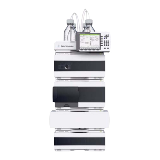
Optimizing the Stack Configuration Optimizing the Stack Configuration One Stack Configuration Ensure optimum performance by installing the modules of the Agilent 1260 Infinity LC in the following configuration (see Figure 8 on page 30 Figure 9 on page 31). This configuration optimizes the flow path for minimum delay volume and minimizes the bench space required. - Page 30 Installing the Column Compartment Optimizing the Stack Configuration Figure 8 Recommended Stack Configuration (Front View) Agilent 1260 Infinity TCC User Manual...
- Page 31 Installing the Column Compartment Optimizing the Stack Configuration Figure 9 Recommended Stack Configuration (Rear View) Agilent 1260 Infinity TCC User Manual...
-
Page 32: Two Stack Configuration
A slightly longer capillary is required between the pump and autosampler. See Figure 10 on page 32 and Figure 11 on page 33. Figure 10 Two stack configuration (front view) Agilent 1260 Infinity TCC User Manual... - Page 33 Installing the Column Compartment Optimizing the Stack Configuration Figure 11 Two stack configuration (rear view) Agilent 1260 Infinity TCC User Manual...
-
Page 34: Installation Information On Leak And Waste Handling
A printed copy of the guideline has been shipped with the solvent cabinet, electronic copies are available on the Internet. Recommendations for Solvent Cabinet N O T E For details, see the usage guideline for the Agilent 1200 Infinity Series Solvent Cabinets. Agilent 1260 Infinity TCC User Manual... - Page 35 Leak pan's outlet port (A), leak funnel (B) and corrugated waste tube (C) Waste tube of the sampler’s needle wash Condense drain outlet of the autosampler cooler Waste tube of the purge valve Waste tube Agilent 1260 Infinity TCC User Manual...
- Page 36 ➔ Do not bend tubes. ➔ Do not immerse tube end in waste liquid. ➔ Do not intubate tubes in other tubes. ➔ For correct tubing follow instructions on label attached to the module. Agilent 1260 Infinity TCC User Manual...
- Page 37 Installing the Column Compartment Installation Information on Leak and Waste Handling Figure 13 Warning label (illustration for correct waste tubing) Agilent 1260 Infinity TCC User Manual...
-
Page 38: Installing The Column Compartment
Never plug the power line back in when cover is removed. 1 Place the column compartment in the stack or on the bench in a horizontal position. Agilent 1260 Infinity TCC User Manual... - Page 39 If an Agilent DAD/MWD/FLD is in the system, the LAN should be connected to the N O T E DAD/MWD/FLD (due to higher data load). 6 Connect the APG Remote cable (optional) for non- Agilent 1260 Infinity modules. Agilent 1260 Infinity TCC User Manual...
- Page 40 The column compartment is turned on when the line power switch is pressed and the green N O T E indicator lamp is illuminated. The column compartment is turned off when the line power switch is protruding and the green light is OFF. Agilent 1260 Infinity TCC User Manual...
-
Page 41: Flow Connections Of The Column Compartment
➔ The volume of substances should be reduced to the minimum required for the analysis. ➔ Do not operate the instrument in an explosive atmosphere. Agilent 1260 Infinity TCC User Manual... - Page 42 16 . N O T E The internal volumes of the heat exchanger assemblies comprise a volume of 3 µl (left) and 6 µl (right). The internal capillary diameter is 0.17 mm. Agilent 1260 Infinity TCC User Manual...
- Page 43 If the column compartment is not part of an Agilent 1200 kit. Infinity Series system, or if an Agilent 1200 Infinity Series autosampler is located on top, connect the corrugated tubing to the waste outlet. Agilent 1260 Infinity TCC User Manual...
- Page 44 The installation of the column compartment has now been completed. Always operate the TCC with the front cover in place for proper thermostatting conditions N O T E and to protect the column area against strong drafts from the ouside. Agilent 1260 Infinity TCC User Manual...
-
Page 45: Placing Columns
Figure 16 on page 45 and Figure 17 on page 45. The Agilent logo should always be at front. Figure 16 Column-Identification Tag for Left Heat Exchanger Figure 17 Column-Identification Tag for Right Heat Exchanger Agilent 1260 Infinity TCC User Manual... -
Page 46: Column Clip
Installing the Column Compartment Placing Columns Column Clip For better positioning of the column on the heat exchanger a column clip is available (see “Accessory Kit” on page 107). Figure 18 Column clip Agilent 1260 Infinity TCC User Manual... -
Page 47: Using The Module
Agilent 1260 Infinity TCC User Manual Using the Module Leak and Waste Handling Solvent Information This chapter explains the operational parameters of the module. Agilent Technologies... -
Page 48: Leak And Waste Handling
N O T E For details, see the usage guideline for the Agilent 1200 Infinity Series Solvent Cabinets. For details on correct installation, see “Installation Information on Leak and Waste Handling” on page 34. Agilent 1260 Infinity TCC User Manual... -
Page 49: Solvent Information
• Avoid or minimize the use of solvents that may corrode parts in the flow path. Consider specifications for the pH range given for different materials like flow cells, valve materials etc. and recommendations in subsequent sections. Agilent 1260 Infinity TCC User Manual... - Page 50 Using the Module Solvent Information Agilent 1260 Infinity TCC User Manual...
-
Page 51: How To Optimize The Column Compartment
Agilent 1260 Infinity TCC User Manual How to optimize the Column Compartment Optimizing the Performance of your Column Compartment This chapter provides information on how to optimize the thermostatted column compartement. Agilent Technologies... -
Page 52: Optimizing The Performance Of Your Column Compartment
• Keep the left and right heat exchanger temperature the same unless you do specific applications. • Assure that the front cover is always closed. Agilent 1260 Infinity TCC User Manual... -
Page 53: Troubleshooting And Diagnostics
Agilent 1260 Infinity TCC User Manual Troubleshooting and Diagnostics Overview of the Module’s Indicators and Test Functions Status Indicators Power Supply Indicator Module Status Indicator Available Tests depending on User Interfaces Agilent Lab Advisor Software Overview about the troubleshooting and diagnostic features. -
Page 54: Overview Of The Module's Indicators And Test Functions
A series of test functions are available for troubleshooting and operational verification after exchanging internal components (see Tests and Calibrations). Thermostat Diagnostic Test The Thermostat Diagnostic Test evaluates the heating and cooling efficiency of the two peltier elements. Agilent 1260 Infinity TCC User Manual... - Page 55 Normally, temperature calibration is not required throughout the lifetime of the instrument. However, in order to comply with local regulatory requirements, calibration and verification may be required. The following sections describe these functions in detail. Agilent 1260 Infinity TCC User Manual...
-
Page 56: Status Indicators
Figure 19 Location of Status indicators Power Supply Indicator The power supply indicator is integrated into the main power switch. When the indicator is illuminated (green) the power is ON. Agilent 1260 Infinity TCC User Manual... -
Page 57: Module Status Indicator
In such a case try to re- boot the module or try a cold- start (see “Special Settings” on page 141. Then try a firmware update (see “Replacing the Module’s Firmware” on page 103). If this does not help, a main board replacement is required. Agilent 1260 Infinity TCC User Manual... -
Page 58: Available Tests Depending On User Interfaces
Preferred tool should be the Agilent Lab Advisor Software, see “Agilent Lab Advisor Software” on page 59. Table 5 Test Functions available vs. User Interface - TCC Test Lab Advisor Software Agilent ChemStation Instant Pilot G4208A Thermostat Function Test Temperature Calibration section Maintenance Agilent 1260 Infinity TCC User Manual... -
Page 59: Agilent Lab Advisor Software
For details refer to the Agilent Lab Advisor software help files. The Instrument Utilities is a basic version of the Lab Advisor with limited functionality required for installation, use and maintenance. No advanced repair, troubleshooting and monitoring functionality is included. Agilent 1260 Infinity TCC User Manual... - Page 60 Troubleshooting and Diagnostics Agilent Lab Advisor Software Agilent 1260 Infinity TCC User Manual...
-
Page 61: Error Information
Agilent 1260 Infinity TCC User Manual Error Information What Are Error Messages General Error Messages Timeout Shutdown Remote Timeout Lost CAN Partner Leak Leak Sensor Open Leak Sensor Short Compensation Sensor Open Compensation Sensor Short TCC Error Messages Left Fan Failed... -
Page 62: What Are Error Messages
In all cases, error propagation is done via the CAN bus or via an APG remote cable (see documentation for the APG interface). Agilent 1260 Infinity TCC User Manual... -
Page 63: General Error Messages
An external instrument has generated a shutdown signal on the remote line. The module continually monitors the remote input connectors for status signals. A LOW signal input on pin 4 of the remote connector generates the error message. Agilent 1260 Infinity TCC User Manual... -
Page 64: Remote Timeout
Check the vacuum degasser for an error The degasser failed to generate sufficient condition. Refer to the Service Manual for the vacuum for solvent degassing. degasser or the 1260 pump that has the degasser built-in. Remote Timeout Error ID: 0070 A not- ready condition is still present on the remote input. -
Page 65: Lost Can Partner
• Ensure all CAN cables are installed correctly. Exchange the CAN cable. Defective CAN cable. Switch off the system. Restart the system, and Defective main board in another module. determine which module or modules are not recognized by the system. Agilent 1260 Infinity TCC User Manual... -
Page 66: Leak
Probable cause Suggested actions Use a higher temperature setpoint. Condensation. Ensure all fittings are tight. Loose column fittings. Exchange defective capillaries. Broken capillary. Exchange the valve seal. Leaking column-switching valve seal. Agilent 1260 Infinity TCC User Manual... -
Page 67: Leak Sensor Open
Probable cause Suggested actions Please contact your Agilent service Defective leak sensor. representative. Please contact your Agilent service Leak sensor incorrectly routed, being representative. pinched by a metal component. Agilent 1260 Infinity TCC User Manual... -
Page 68: Compensation Sensor Open
If the resistance across the sensor falls below the lower limit, the error message is generated. Probable cause Suggested actions Please contact your Agilent service Defective main board. representative. Agilent 1260 Infinity TCC User Manual... -
Page 69: Tcc Error Messages
5 s, the error message is generated. Probable cause Suggested actions Please contact your Agilent service Fan cable disconnected. representative. Please contact your Agilent service Defective fan. representative. Please contact your Agilent service Defective TCC board. representative. Agilent 1260 Infinity TCC User Manual... -
Page 70: Right Fan Failed
OFF, and the error message is generated. Probable cause Suggested actions Please contact your Agilent service The top foam was removed during representative. operation. Please contact your Agilent service Foam not activating the sensor. representative. Agilent 1260 Infinity TCC User Manual... -
Page 71: Cover Violation
The temperature of the left heat exchanger did not reach the temperature setpoint within the timeout threshold. Probable cause Suggested actions Please contact your Agilent service Defective left heater assembly. representative. Please contact your Agilent service Defective TCC board. representative. Agilent 1260 Infinity TCC User Manual... -
Page 72: Right Temperature Timeout
Please contact your Agilent service representative. Flex board not connected (only if all left or right sensor error messages appear simultaneously). Please contact your Agilent service representative. Defective heater assembly. Please contact your Agilent service representative. Defective TCC board. Agilent 1260 Infinity TCC User Manual... -
Page 73: Heater Profile
If the temperature is not changing as expected, the error message is generated. Probable cause Suggested actions Please contact your Agilent service Defective heater assembly. representative. Please contact your Agilent service Defective TCC board. representative. Agilent 1260 Infinity TCC User Manual... -
Page 74: Valve Failed
Probable cause Suggested actions Please contact your Agilent service Defective column-switching valve. representative. Please contact your Agilent service Defective TCC board. representative. Agilent 1260 Infinity TCC User Manual... -
Page 75: Column Temperature
70 °C, the current is switched OFF and the error message is generated. Probable cause Suggested actions Please contact your Agilent service representative. Defective heater assembly. Please contact your Agilent service representative. Defective TCC board. Agilent 1260 Infinity TCC User Manual... -
Page 76: Defective Heater Circuit
OFF the heater (peltier) assemblies, and the error message is generated. Probable cause Suggested actions Please contact your Agilent service Defective TCC board. representative. Agilent 1260 Infinity TCC User Manual... -
Page 77: Test Functions
Agilent 1260 Infinity TCC User Manual Test Functions Thermostat Function Test Evaluating the Thermostat Function Test Pressure Test Column Thermostat Temperature Calibration Temperature Calibration Procedure Temperature Calibration with Agilent Lab Advisor Column Thermostat Calibration Problems Installing the Temperature Sensor This chapter describes the TCC’s built in test functions. -
Page 78: Thermostat Function Test
30 °C is a measure of heating efficiency. Thermostat Function Test Result A typical Thermostat Function Test profile is shown in Figure 20 on page 78. Figure 20 Typical Thermostat Function Test Profile Agilent 1260 Infinity TCC User Manual... - Page 79 Test Functions Thermostat Function Test Thermostat Test with Agilent LabAdvisor 1 1. Select the Thermostat Test and start the test. Figure 21 Thermostat Test Agilent 1260 Infinity TCC User Manual...
-
Page 80: Evaluating The Thermostat Function Test
Poor peltier efficiency (if setpoint temperatures can still be reached, and are stable, there is no requirement to exchange the heater assembly). Exchange the heater assembly. Defective sensors on flex board. Exchange the heater assembly. Defective heater assembly. Agilent 1260 Infinity TCC User Manual... -
Page 81: Pressure Test
Do not use the test for modules having a lower maximum pressure than the pump as this will damage the valve. For example do not use 400 bar valve in a TCC or Flex Cube in combination with a 600 bar pump. Agilent 1260 Infinity TCC User Manual... -
Page 82: Column Thermostat Temperature Calibration
(using the external measuring device, “Temperature Calibration Procedure” on page 83) and the cross- over temperature (36 °C) of both heat exchangers (left and right) are within a range of ± 0.5 °C. Agilent 1260 Infinity TCC User Manual... -
Page 83: Temperature Calibration Procedure
For the measuring and calibration process Agilent Technologies recommends a N O T E thermometer with 0.1 °C precision. Contact the local Agilent Technologies support representative for ordering information. The figures in this procedure refer to a specific type of temperature sensor (Heraeus N O T E Quat340, quartz surface-temperature measurement sensor). - Page 84 1 Select the Temperature Calibration and start the calibration. Figure 23 Temperature Calibration - Step 1 (Start) 2 Wait for the temperature to stabilize at the calibration temperature (36 °C). Figure 24 Temperature Calibration - Step 2 (Wait for stabilization) Agilent 1260 Infinity TCC User Manual...
- Page 85 Figure 26 OnePoint Calibration - Step 4 (Calibration done) 5 Repeat the calibration procedure for the right heat exchanger. Agilent 1260 Infinity TCC User Manual...
- Page 86 “Turning off the 2- point calibration” on page 88. The figures below show the calibration process with the Agilent LabAdvisor software. It is similar to the 1- Point Calibration. Agilent 1260 Infinity TCC User Manual...
- Page 87 Test Functions Column Thermostat Temperature Calibration Figure 27 Two Point Calibration – Start Figure 28 Two Point Calibration – Define the two temperatures Agilent 1260 Infinity TCC User Manual...
- Page 88 2 For right heat exchanger use the command E2PC 1,0 and Execute. The user interface will reply with RA 0000 E2PC 1,0 if command was entered correctly. 3 Perform the “Temperature Calibration” on page xx. Agilent 1260 Infinity TCC User Manual...
-
Page 89: Column Thermostat Calibration Problems
Hardware Failures Probable hardware failures that can lead to a failed calibration procedure are: • Defective or wrongly calibrated measuring device. • Defective heater assembly. • Defective ambient- temperature sensor. • Defective CCM board. Agilent 1260 Infinity TCC User Manual... -
Page 90: Installing The Temperature Sensor
Other sensors may require a different fixing. Remove the front cover. Install the temperature sensor at the measurement position on the left heat exchanger. Route the sensor wire through the slit in the leak tray. Re-install the front cover. Agilent 1260 Infinity TCC User Manual... -
Page 91: Maintenance
Agilent 1260 Infinity TCC User Manual Maintenance Warnings and Cautions Introduction to Maintenance Overview of Maintenance Cleaning the Module Changing Column Identification Tags Replacing Head Parts of Column Switching Valve Correcting Leaks Replacing the Module’s Firmware This chapter describes the maintenance and repair of the TCC. -
Page 92: Warnings And Cautions
Sharp metal edges WA R N I N G Sharp-edged parts of the equipment may cause injuries. ➔ To prevent personal injury, be careful when getting in contact with sharp metal areas. Agilent 1260 Infinity TCC User Manual... - Page 93 C A U T I O N ➔ If you connect external equipment to the instrument, make sure that you only use accessory units tested and approved according to the safety standards appropriate for the type of external equipment. Agilent 1260 Infinity TCC User Manual...
-
Page 94: Introduction To Maintenance
Maintenance Introduction to Maintenance Introduction to Maintenance The main user accessible assemblies of the Agilent 1260 Infinity Thermostatted Column Compartment can be accessed from the front (simple repairs) and don't require to remove the TCC from the system stack. Agilent 1260 Infinity TCC User Manual... -
Page 95: Overview Of Maintenance
“Replacing Head Parts of Column If the valve performance shows Switching Valve” on page 99 indication of leakage or wear “Correcting Leaks” on page 102 If a leak has occurred Check for leaks Agilent 1260 Infinity TCC User Manual... -
Page 96: Cleaning The Module
WA R N I N G hazard and damage the module ➔ Do not use an excessively damp cloth during cleaning. ➔ Drain all solvent lines before opening any connections in the flow path. Agilent 1260 Infinity TCC User Manual... -
Page 97: Changing Column Identification Tags
98. The Agilent logo should always be at front. When correctly placed on the heat exchanger, the distance between tag and tag reader is 1 – 2 mm. This is the optimum distance for proper function. Agilent 1260 Infinity TCC User Manual... - Page 98 Column-Identification Tag for Right Heat Exchanger 3 For columns with small diameter, a cable tie wrap should be used to fix the column identification tag to the column. Assure that the tie wrap does not block the front cover. Agilent 1260 Infinity TCC User Manual...
-
Page 99: Replacing Head Parts Of Column Switching Valve
Replacing Head Parts of Column Switching Valve Figure 33 Column Switching Valve Parts When If valve leaks. Tools required Description Wrench, 1/4 inch (supplied in HPLC Tool-Kit) Hexagonal key, 9/64 inch (supplied in HPLC Tool-Kit) Agilent 1260 Infinity TCC User Manual... - Page 100 9 Place the new (if required) stator face in place on the stator head. Reinstall the stator head. 10 Insert the stator screws in the stator head. Tighten the screws alternately two turns at a time until the stator head is secure. Agilent 1260 Infinity TCC User Manual...
- Page 101 For example do not use 400 bar valve in a TCC or Flex Cube in combination with a 600 bar pump. 12 Perform a Pressure Test to ensure the valve is pressure tight. Agilent 1260 Infinity TCC User Manual...
-
Page 102: Correcting Leaks
2 Use a pipette and tissue to dry the leak sensor area. 3 Observe the capillary connections and the column switching valve for leaks and correct, if required. 4 Re- install the front cover. Figure 34 Possible Leak Areas Agilent 1260 Infinity TCC User Manual... -
Page 103: Replacing The Module's Firmware
1 Download the required module firmware, the latest LAN/RS- 232 FW Update Tool and the documentation from the Agilent web. • http://www.chem.agilent.com/_layouts/agilent/downloadFirmware.aspx? whid=69761 2 For loading the firmware into the module follow the instructions in the documentation. Agilent 1260 Infinity TCC User Manual... - Page 104 Module Specific Information (G1316A/B) G1316A Initial firmware (main and resident) Depends on main board revision. Newer versions (G1316-66530 and higher) allow A.05.05 and above only. Compatibility with 1100 / 1200 series modules always Conversion to / emulation Agilent 1260 Infinity TCC User Manual...
-
Page 105: Parts For Maintenance
Agilent 1260 Infinity TCC User Manual Parts for Maintenance Column Switching Valve 2 Position/6 Port Kits Accessory Kit Spring Kit Plastic Parts Leak Parts This chapter provides information on parts for maintenance. Agilent Technologies... -
Page 106: Column Switching Valve 2 Position/6 Port
Capillary Kit Column Switching includes two capillaries (0.17 mm i.d., 180 mm) and three capillaries (0.17 mm i.d., 90 mm) 5068-0018 Stator screws 0101-1417 Stator head 5068-0118 Stator ring 0101-1409 Rotor Seal 1535-4045 Bearing ring Figure 35 Column Switching Valve Parts Agilent 1260 Infinity TCC User Manual... -
Page 107: Kits
G1316-87300 Capillary ST 0.17 x 90 mm S/S 5181-1516 CAN cable, Agilent module to module, 0.5 m Spring Kit Description G1316-68733 Spring kit for G1316A (1100 Series) G1316-68734 Spring kit for G1316A/B (1200 Series) Agilent 1260 Infinity TCC User Manual... -
Page 108: Plastic Parts
Parts for Maintenance Plastic Parts Plastic Parts Item Description G1316-68714 Front Cover C (NEW) G1316-68734 Spring kit for Front Cover (NEW) 5043-0207 Name plate 1260 Figure 36 Plastic Parts Agilent 1260 Infinity TCC User Manual... -
Page 109: Leak Parts
Parts for Maintenance Leak Parts Leak Parts Item Description G1316-67000 Leak tube kit includes following items: Funnel holder G1316C, tubing-flex polyethylene, leak funnel G1316-42303 Capillary guide Figure 37 Leak Parts Agilent 1260 Infinity TCC User Manual... - Page 110 Parts for Maintenance Leak Parts Agilent 1260 Infinity TCC User Manual...
-
Page 111: Identifying Cables
Identifying Cables Cable Overview Analog Cables Remote Cables BCD Cables CAN/LAN Cables External Contact Cable Agilent Module to PC Agilent 1200 Module to Printer This chapter provides information on cables used with the 1260 Infinity series of HPLC modules. Agilent Technologies... -
Page 112: Cable Overview
Identifying Cables Cable Overview Cable Overview Never use cables other than the ones supplied by Agilent Technologies to ensure proper N O T E functionality and compliance with safety or EMC regulations. Analog cables Description 35900-60750 Agilent module to 3394/6 integrators... - Page 113 It's also called "Null Modem Cable" with full handshaking where the wiring is made between pins 1-1, 2-3, 3-2, 4-6, 5-5, 6-4, 7-8, 8-7, 9-9. 5181-1561 RS-232 cable, 8 m Agilent 1260 Infinity TCC User Manual...
-
Page 114: Analog Cables
Agilent modules. The other end depends on the instrument to which connection is being made. Agilent Module to 3394/6 Integrators p/n 35900-60750 Pin 3394/6 Pin Agilent Signal Name module Not connected Shield Analog - Center Analog + Agilent 1260 Infinity TCC User Manual... - Page 115 Pin BNC Pin Agilent Signal Name module Shield Shield Analog - Center Center Analog + Agilent Module to General Purpose p/n 01046-60105 Pin Agilent Signal Name module Not connected Black Analog - Analog + Agilent 1260 Infinity TCC User Manual...
-
Page 116: Remote Cables
Identifying Cables Remote Cables Remote Cables One end of these cables provides a Agilent Technologies APG (Analytical Products Group) remote connector to be connected to Agilent modules. The other end depends on the instrument to be connected to. Agilent Module to 3396A Integrators... - Page 117 Not connected 6 - Yellow 6 - Yellow Power on High 7 - Red 7 - Red Ready High 8 - Green 8 - Green Stop 9 - Black 9 - Black Start request Agilent 1260 Infinity TCC User Manual...
- Page 118 01046-60201 Wire Color Pin Agilent Signal Name Active module (TTL) White Digital ground Brown Prepare run Gray Start Blue Shut down Pink connected Yellow Power on High Ready High Green Stop Black Start request Agilent 1260 Infinity TCC User Manual...
-
Page 119: Bcd Cables
Black BCD 0 Orange BCD 3 BCD 2 Brown BCD 1 Gray Digital ground Gray Gray/pink BCD 11 Red/blue BCD 10 White/green BCD 9 Brown/green BCD 8 not connected not connected + 5 V Agilent 1260 Infinity TCC User Manual... - Page 120 Agilent Module to 3396 Integrators p/n 03396-60560 Pin 3396 Pin Agilent Signal Name BCD Digit module BCD 5 BCD 7 BCD 6 BCD 4 BCD0 BCD 3 BCD 2 BCD 1 Digital ground + 5 V Agilent 1260 Infinity TCC User Manual...
-
Page 121: Can/Lan Cables
CAN cable, Agilent module to module, 1 m LAN Cables Description 5023-0203 Cross-over network cable, shielded, 3 m (for point to point connection) 5023-0202 Twisted pair network cable, shielded, 7 m (for point to point connection) Agilent 1260 Infinity TCC User Manual... -
Page 122: External Contact Cable
EXT 2 Grey EXT 3 Pink EXT 3 Blue EXT 4 EXT 4 Black Not connected Violet Not connected Grey/pink Not connected Red/blue Not connected White/green Not connected Brown/green Not connected White/yellow Not connected Agilent 1260 Infinity TCC User Manual... -
Page 123: Agilent Module To Pc
It's also called "Null Modem Cable" with full handshaking where the wiring is made between pins 1-1, 2-3, 3-2, 4-6, 5-5, 6-4, 7-8, 8-7, 9-9. 5181-1561 RS-232 cable, 8 m Agilent 1260 Infinity TCC User Manual... -
Page 124: Agilent 1200 Module To Printer
Agilent 1200 Module to Printer Description 5181-1529 Cable Printer Serial & Parallel, is a SUB-D 9 pin female vs. Centronics connector on the other end (NOT FOR FW UPDATE). For use with G1323 Control Module. Agilent 1260 Infinity TCC User Manual... -
Page 125: Hardware Information
Agilent 1260 Infinity TCC User Manual Hardware Information Firmware Description Electrical Connections Serial Number Information 1260 Infinity Electrical Connections Interfaces Overview Interfaces Setting the 8-bit Configuration Switch (without On-Board LAN) Communication Settings for RS-232C Special Settings Instrument Layout This chapter describes the detector in more detail on hardware and electronics. -
Page 126: Firmware Description
• an instrument specific section, called main system Resident System This resident section of the firmware is identical for all Agilent 1100/1200/1220/1260/1290 series modules. Its properties are: • the complete communication capabilities (CAN, LAN and RS- 232C) • memory management •... - Page 127 Update of main system can be done in the resident system only. Update of the resident N O T E system can be done in the main system only. Main and resident firmware must be from the same set. Figure 38 Firmware Update Mechanism Agilent 1260 Infinity TCC User Manual...
- Page 128 All these specific informations are described in the documentation provided with the firmware update tools. The firmware update tools, firmware and documentation are available from the Agilent web. • http://www.chem.agilent.com/_layouts/agilent/downloadFirmware.aspx?whid=69761 Agilent 1260 Infinity TCC User Manual...
-
Page 129: Electrical Connections
There are no externally accessible fuses, because automatic electronic fuses are implemented in the power supply. Never use cables other than the ones supplied by Agilent Technologies to ensure proper N O T E functionality and compliance with safety or EMC regulations. -
Page 130: Serial Number Information 1260 Infinity
00000 Serial number Figure 39 Rear View of the Thermostatted Column Compartment The GPIB interface has been removed with the introduction of the 1260 Infinity modules. N O T E Agilent 1260 Infinity TCC User Manual... -
Page 131: Interfaces
G1364C FC-AS G1330B/K1330B μ CAN-DC- OUT for CAN G1364D FC- slaves G1367E HiP ALS K1367E HiP ALS Clinical Ed. G1377A HiP micro ALS G2258A DL ALS G5664A Bio-inert FC-AS G5667A Bio-inert Autosampler G4226A ALS Agilent 1260 Infinity TCC User Manual... - Page 132 K1321B FLD Clinical Ed. G1321C FLD G1362A RID G4280A ELSD EXT Contact AUTOZERO Others G1170A Valve Drive G1316A/C TCC K1316C TCC Clinical Ed. G1322A DEG K1322A DEG Clinical Ed. G1379B DEG G4225A DEG K4225A DEG Clinical Ed. Agilent 1260 Infinity TCC User Manual...
- Page 133 • CAN connectors as interface to other modules • LAN connector as interface to the control software • RS- 232C as interface to a computer • REMOTE connector as interface to other Agilent products • Analog output connector(s) for signal output Agilent 1260 Infinity TCC User Manual...
-
Page 134: Overview Interfaces
• one start bit and one stop bit are always used (not selectable). The RS- 232C is designed as DCE (data communication equipment) with a 9- pin male SUB- D type connector. The pins are defined as: Agilent 1260 Infinity TCC User Manual... - Page 135 RS-232C Connection Table Direction Function Ground Figure 40 RS-232 Cable Analog Signal Output The analog signal output can be distributed to a recording device. For details refer to the description of the module’s main board. Agilent 1260 Infinity TCC User Manual...
- Page 136 APG Remote The APG Remote connector may be used in combination with other analytical instruments from Agilent Technologies if you want to use features as common shut down, prepare, and so on. Remote control allows easy connection between single instruments or systems to ensure coordinated analysis with simple coupling requirements.
- Page 137 START REQUEST (L) Request to start injection cycle (for example, by start key on any module). Receiver is the autosampler. Special Interfaces There is no special interface for this module. Agilent 1260 Infinity TCC User Manual...
-
Page 138: Setting The 8-Bit Configuration Switch (Without On-Board Lan)
N O T E Switch settings provide configuration parameters for serial communication protocol and instrument specific initialization procedures. With the introduction of the Agilent 1260 Infinity, all GPIB interfaces have been removed. N O T E The preferred communication is LAN. -
Page 139: Communication Settings For Rs-232C
Use the following tables for selecting the setting which you want to use for RS- 232C communication. The number 0 means that the switch is down and 1 means that the switch is up. Agilent 1260 Infinity TCC User Manual... - Page 140 Parity No Parity Odd Parity Even Parity One start bit and one stop bit are always used (not selectable). Per default, the module will turn into 19200 baud, 8 data bit with no parity. Agilent 1260 Infinity TCC User Manual...
-
Page 141: Special Settings
Save your methods and data before executing a forced cold start. If you use the following switch settings and power the instrument up again, a forced cold start has been completed. Table 17 Forced Cold Start Settings (without on-board LAN) Mode Select TEST/BOOT Agilent 1260 Infinity TCC User Manual... -
Page 142: Instrument Layout
• the plastic layers help cushion the electronic and mechanical parts from physical shock, and • the metal inner cabinet shields the internal electronics from electromagnetic interference and also helps to reduce or eliminate radio frequency emissions from the instrument itself. Agilent 1260 Infinity TCC User Manual... -
Page 143: Appendix
Agilent 1260 Infinity TCC User Manual Appendix General Safety Information Safety Symbols General Safety Information Safety Standards Operation The Waste Electrical and Electronic Equipment (WEEE) Directive (2002/96/EC) Lithium Batteries Information Radio Interference Sound Emission Use of Solvents Agilent Technologies on Internet This chapter provides addition information on safety, legal and web. -
Page 144: General Safety Information
C A U T I O N alerts you to situations that could cause loss of data, or damage of equipment. ➔ Do not proceed beyond a caution until you have fully understood and met the indicated conditions. Agilent 1260 Infinity TCC User Manual... -
Page 145: General Safety Information
Agilent Technologies assumes no liability for the customer’s failure to comply with these requirements. Ensure the proper usage of the equipment. - Page 146 When working with solvents, observe appropriate safety procedures (for example, goggles, safety gloves and protective clothing) as described in the material handling and safety data sheet by the solvent vendor, especially when toxic or hazardous solvents are used. Agilent 1260 Infinity TCC User Manual...
-
Page 147: The Waste Electrical And Electronic Equipment (Weee) Directive (2002/96/Ec)
“Monitoring and Control instrumentation” product. Do not dispose off in domestic household waste To return unwanted products, contact your local Agilent office, or see www.agilent.com for more information. Agilent 1260 Infinity TCC User Manual... -
Page 148: Lithium Batteries Information
Ved udskiftning benyttes kun batteri som anbefalt av apparatfabrikanten. ➔ Brukt batteri returneres appararleverandoren. Bij dit apparaat zijn batterijen geleverd. Wanneer deze leeg zijn, moet u ze niet weggooien N O T E maar inleveren als KCA. Agilent 1260 Infinity TCC User Manual... -
Page 149: Radio Interference
Appendix Radio Interference Radio Interference Never use cables other than the ones supplied by Agilent Technologies to ensure proper functionality and compliance with safety or EMC regulations. Test and Measurement If test and measurement equipment is operated with equipment unscreened cables and/or used for measurements on open set- ups, the user has to assure that under operating conditions the radio interference limits are still met within the premises. -
Page 150: Sound Emission
This product has a sound pressure emission (at the operator position) < 70 dB. • Sound Pressure Lp < 70 dB (A) • At Operator Position • Normal Operation • According to ISO 7779:1988/EN 27779/1991 (Type Test) Agilent 1260 Infinity TCC User Manual... -
Page 151: Use Of Solvents
THF, dioxane, di- isopropylether) such ethers should be filtered through dry aluminium oxide which adsorbs the peroxides, • Solvents containing strong complexing agents (e.g. EDTA), • Mixtures of carbon tetrachloride with 2- propanol or THF. Agilent 1260 Infinity TCC User Manual... -
Page 152: Agilent Technologies On Internet
Appendix Agilent Technologies on Internet Agilent Technologies on Internet For the latest information on products and services visit our worldwide web site on the Internet at: http://www.agilent.com Agilent 1260 Infinity TCC User Manual... - Page 153 Communication settings left fan failed RS-232C left temperature timeout cable compensation sensor open lost CAN partner analog compensation sensor short open cover condensation remote timeout Configuration Agilent 1260 Infinity TCC User Manual...
- Page 154 103, humidity overview message replacing firmware 103, remote timeout right fan failed installation right temperature timeout bench space RS-232C non-operating altitude capillaries and waste tubings cable Agilent 1260 Infinity TCC User Manual...
- Page 155 Agilent 1260 Infinity TCC User Manual...
- Page 156 In This Book This manual contains technical reference information about the Agilent 1260 Infinity Thermostatted Column Compartment (G1316A TCC). The manual describes the following: • introduction and specifications, • installation, • using and optimizing, • troubleshooting and diagnose, • maintenance, •...