Kyocera KM-2540 Service Manual
Fax system (p)v
Hide thumbs
Also See for KM-2540:
- Service manual (365 pages) ,
- Operation manual (208 pages) ,
- Advanced operation manual (136 pages)

Related Manuals for Kyocera KM-2540


Summary of Contents for Kyocera KM-2540
- Page 1 FAX System (P) SERVICE MANUAL Published in August 2007 843LH110 3LHSM060 First Edition...
- Page 2 CAUTION RISK OF EXPLOSION IF BATTERY IS REPLACED BY AN INCORRECT TYPE. DISPOSE OF USED BATTERIES ACCORDING TO THE INSTRUCTIONS. It may be illegal to dispose of this battery into the municipal waste stream. Check with your local solid waste officials for details in your area for proper disposal. ATTENTION IL Y A UN RISQUE D’EXPLOSION SI LA BATTERIE EST REMPLACEE PAR UN MODELE DE TYPE INCORRECT.
- Page 3 Revision history Revision Date Replaced pages Remarks...
- Page 4 This page is intentionally left blank.
-
Page 5: Safety Precautions
Safety precautions This booklet provides safety warnings and precautions for our service personnel to ensure the safety of their customers, their machines as well as themselves during maintenance activities. Service personnel are advised to read this booklet carefully to familiarize themselves with the warnings and precautions described here before engaging in maintenance activities. - Page 6 Safety warnings and precautions Various symbols are used to protect our service personnel and customers from physical danger and to prevent damage to their property. These symbols are described below: DANGER: High risk of serious bodily injury or death may result from insufficient attention to or incorrect compliance with warning messages using this symbol.
-
Page 7: Installation Precautions
1.Installation Precautions WARNING • Do not use a power supply with a voltage other than that specified. Avoid multiple connections to one outlet: they may cause fire or electric shock. When using an extension cable, always check that it is adequate for the rated current....................•... - Page 8 2.Precautions for Maintenance WARNING • Always remove the power plug from the wall outlet before starting machine disassembly....• Always follow the procedures for maintenance described in the service manual and other related brochures............................• Under no circumstances attempt to bypass or disable safety features including safety mechanisms and protective circuits.
- Page 9 • Do not remove the ozone filter, if any, from the copier except for routine replacement..... • Do not pull on the AC power cord or connector wires on high-voltage components when removing them; always hold the plug itself...................... •...
- Page 10 This page is intentionally left blank.
-
Page 11: Table Of Contents
CONTENTS 1-1 Specifications 1-1-1 Specifications............................1-1-1 1-1-2 Parts names............................1-1-4 (1) Main body............................1-1-4 (2) Operation panel..........................1-1-5 1-1-3 Mechanical construction .........................1-1-6 1-2 Installation 1-2-1 Installation environment ..........................1-2-1 1-2-2 Unpacking and installation ........................1-2-2 (1) Installation procedure ........................1-2-2 1-3 Maintenance Mode 1-3-1 Maintenance mode ..........................1-3-1 (1) Maintenance mode item list.......................1-3-1 (2) Contents of maintenance mode items....................1-3-4 1-3-2 System settings.............................1-3-38... - Page 12 This page is intentionally left blank.
-
Page 13: Specifications
1-1 Specifications 1-1-1 Specifications Type ............Optional Fax Kit Compatibility ..........Group 3 Line requirement........Subscription telephone line Transmission speed........Within 3 seconds (33600 bps, JBIG, ITU-T #1 chart) Modem speed ..........33600/31200/28800/26400/24000/21600/19200/16800/14400/12000/9600/ 7200/4800/2400 bps Data compression ........JBIG/MMR/MR/MH Error correction .......... ECM Maximum document dimensions .... - Page 14 Reception functions Manual reception Automatic reception Fax/telephone auto selection TAD reception D.R.D. reception*1 Remote switching Transmission functions One-touch dialing*2 Program dialing*2 Group dialing*2 Chain dialing*2 Redialing (manual/automatic) Dial confirmation Communication functions Direct feed transmission Memory transmission Direct reception Memory reception (subaddress-based confidential reception and relay broadcast reception) Additional communication func- Broadcast transmission (up to 300 numbers)
- Page 15 Reports Activity report Transmission report Reception report Power failure report Delayed communication report Confirmation report User settings list Encryption key list Management report Department list One-touch key list Telephone directory list Program dial list Group dial list Subaddress confidential box list Subaddress relay box list Encryption box list Others...
-
Page 16: Parts Names
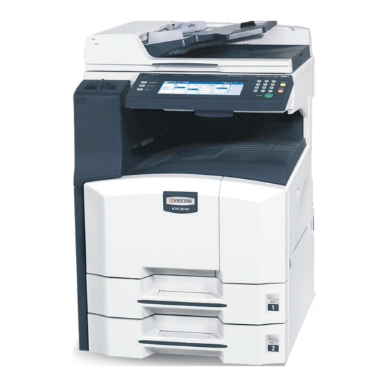
1-1-2 Parts names (1) Main body Figure 1-1-1 Operation panel Document Processor Line jack (L) Original table Telephone jack (T) Original width guides Main power switch Top cover Original eject table Opening handle 10. Original placement indicator 11. Original stopper 1-1-4... -
Page 17: Operation Panel
(2) Operation panel Figure 1-1-2 Touch panel Numeric keys Start key/indicator Fax key/indicator Fax lamp Reset key Stop/Clear key Print management key/indicator System menu/Counter key 10. Interrupt key/indicator 11. Power key/indicator 1-1-5... -
Page 18: Mechanical Construction
1-1-3 Mechanical construction Touch panel LCDPWB MPWB YC12 OPWB-U FCPWB OPWB-L BUBAT NCUPWB OPWB-R YC11 Back light Figure 1-1-3 1-1-6... -
Page 19: Installation Environment
1-2 Installation 1-2-1 Installation environment Installation location (Be based on the machine establishment place.) Avoid direct sunlight or bright lighting. Ensure that the photo-conductor will not be exposed to direct sunlight or other strong light when removing paper jams. Avoid extremes of temperature and humidity, abrupt ambient temperature changes, and hot or cold air directed onto the machine. -
Page 20: Unpacking And Installation
1-2-2 Unpacking and installation (1) Installation procedure Figure 1-2-1 Unpacking Fax unit FCC approval label Antistatic air-padded bag (120 V specifications only) Bottom pad 10. Line approval label Outer case (Australian/New zealand specifica- Upper pad tions only) Plastic bag 11. M3 x 6 screws Modular connector cable 12. - Page 21 Initialization procedure after installation of facsimile system 1. Insert the machine power plug to the wall outlet and turn the main power switch on. 2. Run maintenance item U601. 3. Enter a destination code using the numeric keys (refer to the destination code list) and then press the start key.
- Page 22 This page is intentionally left blank. 1-2-4...
-
Page 23: Maintenance Mode
1-3 Maintenance Mode 1-3-1 Maintenance mode (1) Maintenance mode item list Item Section Content of maintenance item Initial setting* U600 Initializing all data U601 Initializing permanent data U602 Setting factory defaults U603 Setting the user registration data Setting the self telephone number Setting the type of telephone line Setting the number of rings in the fax/telephone auto select mode Setting remote diagnostic transmission... - Page 24 Item Section Content of maintenance item Initial setting* U609 Setting communication time Setting the T0 time-out time Setting the T1 time-out time Setting the T2 time-out time Setting the Ta time-out time Setting the Tb1 time-out time Setting the Tb2 time-out time Setting the Tc time-out time Setting the Td time-out time U610...
- Page 25 Item Section Content of maintenance item Initial setting* U660 Setting the system (communication 2) Setting the criteria for receiving a TCF signal 2 Setting the short protocol transmission Setting the reception of a short protocol transmission Setting the CNG detection times in the fax/telephone auto select mode Setting ECM for each one-touch key U670...
-
Page 26: Contents Of Maintenance Mode Items
(2) Contents of maintenance mode items Maintenance Description item No. Initializing all data U600 Description Initializes software switches and all data in the backup data on the fax control PWB, according to the destina- tion and OEM. Executes the check of the file system, when abnormality of the file system is detected, initializes the file sys- tem, communication past record and register setting contents. - Page 27 Maintenance Description item No. Initializing permanent data U601 Description Initializes software switches other than that for machine data on the fax control PWB according to the destina- tion and OEM. Purpose To initialize the fax control PWB without changing user registration data and factory settings. Method 1.
- Page 28 Maintenance Description item No. Setting the user registration data U603 Description Makes user settings to enable the use of the machine as a fax. Purpose To be run after installation of the facsimile kit if necessary. Start 1. Press the start key. The screen for selecting an item is displayed. 2.
- Page 29 Maintenance Description item No. Clearing data U604 Description Initializes data related to the fax transmission such as transmission history and IDs. Purpose To clear the transmission history or if an ID has been forgotten. Method 1. Press the start key. The screen for selecting an item is displayed. 2.
- Page 30 Maintenance Description item No. Setting an alarm for when reception is completed U605 1. Enter 1 or 2 using the numeric keys to change the setting. Display Description 1: ON An alarm rings. 2: OFF An alarm does not ring. 2.
- Page 31 Maintenance Description item No. Setting the continuous detection time for remote switching U605 Sets the detection time when continuous detection is selected for remote switching. (This setting item will be displayed, but the setting made is ineffective.) 1. Change the setting using the numeric keys. Description Setting range Continuous detection time for remote switching...
- Page 32 Maintenance Description item No. Setting the date format U606 Selects the date format on the respective reports and sender's information record. (cont.) 1. Change the setting using the numeric keys. Display Description 1: YMD Year/month/day 2: MDY Month/day/year 3: DMY Day/month/year 2.
- Page 33 Maintenance Description item No. Setting the system (communication 1) U607 Description Makes settings for fax transmission regarding the communication. Start 1. Press the start key. The screen for selecting an item is displayed. 2. Select the item to be set. The screen for the selected item appears.
- Page 34 Maintenance Description item No. Setting the mode for remote switching U607 Sets the signal detection method for remote switching. Be sure to change the setting according to the type of (cont.) telephone connected to the machine. 1. Enter 1 or 2 using the numeric keys to change the setting. Display Description 1: ONE...
- Page 35 Maintenance Description item No. Setting transmission U608 Description Makes settings regarding fax transmission. Start 1. Press the start key. The screen for selecting an item is displayed. 2. Select the item to be set. The screen for the selected item appears. Display Description ERROR DEALING...
- Page 36 Maintenance Description item No. Setting the waiting period to prevent echo problems at the sender U608 Sets the period before a DCS signal is sent after a DIS signal is received. Used when problems occur due to (cont.) echoes at the sender. 1.
- Page 37 Maintenance Description item No. Setting the frequency of the CED signal U608 Sets the frequency of the CED signal. Used as one of the measures to improve transmission performance for (cont.) international communications. 1. Enter 1 or 2 using the numeric keys to change the frequency. Display Description 1: 2100...
- Page 38 Maintenance Description item No. Setting the T2 time-out time U609 The T2 time-out time decides the following. (cont.) From CFR signal output to image data reception From image data reception to the next signal reception In ECM, from RNR signal detection to the next signal reception 1.
- Page 39 Maintenance Description item No. Setting the Tc time-out time U609 In the TAD mode, set the time to check if there are any triggers for shifting to fax reception after a connected (cont.) telephone receives a call. Only the telephone function is available if shifting is not made within the set Tc time. In the TAD mode, change the setting when fax reception is unsuccessful or a telephone fails to receive a call.
- Page 40 Maintenance Description item No. Setting the modem output level U610 Description Sets the modem output level. Start 1. Press the start key. The screen for selecting an item is displayed. 2. Select the item to be set. The screen for the selected item appears. Display Description SGL LVL MODEM...
- Page 41 Maintenance Description item No. G3 cable equalizer U611 Description Sets the G3 cable equalizer. Start 1. Press the start key. The screen for selecting an item is displayed. 2. Select the item to be set. The screen for the selected item appears. Display Description REG.
- Page 42 Maintenance Description item No. Setting the DTMF output level U613 Description Sets the DTMF output level of a push-button dial telephone. Purpose Used if problems occur when sending a signal with a push-button dial telephone. Start 1. Press the start key. The screen for selecting an item is displayed. 2.
- Page 43 Maintenance Description item No. Adjusting the DTMF output level U614 Description Adjusts the DTMF output level of a push-button dial telephone. Purpose No change is necessary from the factory default. Start 1. Press the start key. The screen for selecting an item is displayed. 2.
- Page 44 Maintenance Description item No. Setting the NCU U615 Description Makes setting regarding the network control unit (NCU). Purpose To be set when installing the facsimile kit. Start 1. Press the start key. The screen for selecting an item is displayed. 2.
- Page 45 Maintenance Description item No. Setting for a PBX U615 Selects the mode to connect an outside call when connected to a PBX. (cont.) According to the type of the PBX connected, select the mode to connect an outside call. 1. Change the setting using the numeric keys. Display Description 1: EARTH...
- Page 46 Maintenance Description item No. Outputting lists U617 Description Outputs a list of data regarding fax. Purpose To check conditions of use, settings and transmission procedures of the fax. Method 1. Press the start key. The screen for selecting an item is displayed. 2.
- Page 47 Maintenance Description item No. Setting the system 1 U650 Description Makes settings for fax reception regarding the sizes of the fax paper and received images and automatic print- ing of the protocol list. Start 1. Press the start key. The screen for selecting an item is displayed. 2.
- Page 48 Maintenance Description item No. Setting the number of lines to be ignored when receiving a fax (A4R, letter) in the auto reduction mode U650 Sets the maximum number of lines to be ignored if the received data volume exceeds the recording capacity (cont.) when the data is recorded in the auto reduction mode onto A4R or letter-size paper under the conditions below.
- Page 49 Maintenance Description item No. Setting the system 2 U651 Description Sets the variation range in rotation reception and the number of adjustment lines for automatic reduction. Start 1. Press the start key. The screen for selecting an item is displayed. 2.
- Page 50 Maintenance Description item No. Setting the system (communication 2) U660 Description Makes settings for fax transmission regarding the communication. Purpose To reduce transmission errors when a low quality line is used. Start 1. Press the start key. The screen for selecting an item is displayed. 2.
- Page 51 Maintenance Description item No. Setting the CNG detection times in the fax/telephone auto select mode U660 Sets the CNG detection times in the fax/telephone auto select mode. (cont.) 1. Change the setting using the numeric keys. Display Description 1: 1 TIME Detects CNG once.
- Page 52 Maintenance Description item No. Setting the system (communication 3) U670 Description Makes settings for fax transmission regarding the communication. Purpose To reduce transmission errors when a low quality line is used. Start 1. Press the start key. The screen for selecting an item is displayed. 2.
- Page 53 Maintenance Description item No. Setting the V.34 symbol speed (2800 Hz) U670 Sets if the V.34 symbol speed 2800 Hz is used. (cont.) 1. Enter 1 or 2 using the numeric keys to change the setting. Display Description 1: ON V.34 symbol speed 2800 Hz is used.
- Page 54 Maintenance Description item No. List of Software Switches of Which the Setting Can Be Changed U882 <System setting> (cont.) Item 0 One-touch name and telephone number display on the destination check screen 5 Communication end buzzer after reception 1 Ringer frequency detection method 0 Top-bottom inversion in duplex reception 5 Setting the output priority when A5 size reception 7 F code check in NW-FAX reception...
- Page 55 Maintenance Description item No. List of Software Switches of Which the Setting Can Be Changed U882 <Communication control procedure> (cont.) Item 2 Automatic reception level adjustment (V. 17) 1 Automatic reception level adjustment (V. 29) 0 Automatic reception level adjustment (V. 27ter) 7654 Coding format in transmission 3210 Coding format in reception 5 33600 bps/V34...
- Page 56 Maintenance Description item No. List of Software Switches of Which the Setting Can Be Changed U882 <Modem setting> (cont.) Item 5 Equalizer freeze 76543210 RTH offset (lower byte) 76543210 RTH offset (upper byte) <NCU setting> Item 7654 Dial tone/busy tone detection pattern 7654 Busy tone detection pattern 1 Busy tone detection in automatic FAX/TEL switching 76543210 Access code registration for connection to PSTN...
- Page 57 Maintenance Description item No. Performing board test U894 Description Performs tests on the DRAM (image memory, bitmap memory) and optional memory on the fax control PWB. Purpose To check if reading and writing are performed correctly in respective installed memories. Start 1.
- Page 58 Maintenance Description item No. Setting backup data reading/writing U917 Description Stores backup data from the fax control PWB into CompactFlash or reads the data from CompactFlash. Purpose To store and write data when replacing the PWB. Setting 1. Press the power key on the operation panel, and after verifying the power indicator has gone off, switch off the main power switch.
- Page 59 Maintenance Description item No. Rewriting FAX program U926 Description Downloads the fax program and fax fonts when installing an fax kit. Purpose To run when upgrading the fax program and fax fonts. Setting 1. Press the power key on the operation panel, and after verifying the power indicator has gone off, switch off the main power switch.
-
Page 60: System Settings
1-3-2 System settings In addition to a maintenance function, the machine is equipped with a system settings which can be operated by users (mainly by the machine administrator). In this machine system settings, default settings can be changed. (1) Executing a system setting item Fax default setting Resistration Start... -
Page 61: Fax Default
(2) Fax default Bulletin board setting Enter documents into memory once and they will be Line type setting (inch version only) available for transmission to any number of receiving par- Set the type of phone line here to correspond to the type ties upon receipt of their polling request. - Page 62 TX mode/default setting Remote diagnosis setting Select which transmission mode, Memory Transmission Set to take advantage of our remote diagnosis system. or Direct Feed Transmission, will be the default setting in 1. Select [Remote Diag. (Remote diagn.)] using the this fax. cursor up/down keys and press [Change #].
-
Page 63: Registration
(3) Registration Registering new group dial keys Register multiple destination fax (telephone) numbers Registering new one-touch keys and names under a one-touch key for group dialing. Register destination fax (telephone) numbers and names 1. Press [Dial]. under one-touch keys. 2. Press an unregistered speed-dial key on the touch 1. - Page 64 Setting the current date and time Registering new encryption boxes Set the date and the time that will appear in the message Register encryption boxes for receiving encrypted trans- display. missions. Up to 15 boxes can be registered. 1. Press [Date & Time]. 1.
- Page 65 Registering the fax forwarding information Register the destination and designated hours for fax for- warding. 1. Press [Fax Forwarding]. 2. Enter the fax number of the destination fax number using the numeric keys, abbreviated numbers, one- touch keys or chain dial keys. 3.
- Page 66 This page is intentionally left blank. 1-3-44...
-
Page 67: Error Codes
1-4 Error Codes 1-4-1 Error codes (1) Error code Error codes are listed on the communication reports, activity report, etc. The codes consist of an error code indication U followed by a 5-digit number. (Error codes for V34 communication errors start with an E indication, followed by five digits.) The upper three of the five digits indicate general classification of the error and its cause, while the lower two indicate the detailed classification. -
Page 68: Table Of General Classification
(2) Table of general classification Error code Description U00000 No response or busy after the set number of redials. U00100 Transmission was interrupted by a press of the stop/clear key. U00200 Reception was interrupted by a press of the stop/clear key. U00300 Recording paper on the destination unit has run out during transmission. - Page 69 Error code Description U03400 Polling reception was interrupted because of a mismatch in individual numbers (destination unit is either of our make or by another manufacturer). U03500 In confidential polling reception, the specified confidential box No. was not registered in the desti- nation.
-
Page 70: U004Xx Error Code Table: Interrupted Phase B
(2-1) U004XX error code table: Interrupted phase B Error code Description U00420 A relay request was received from the host center but interrupted because of a mismatch in permit ID or telephone number. U00421 Subaddress-based relay reception was interrupted because of a mismatch in the specified subad- dress relay box number. -
Page 71: U006Xx Error Code Table: Problems With The Unit
(2-2) U006XX error code table: Problems with the unit Error code Description U00600 The document processor cover is open. U00601 Document jam or the document length exceeds the maximum. U00602 Image scanning section problem. U00603 No document feed. U00604 Document length exceeded the limit of the bitmap memory capacity. U00610 Recording section cover is open. -
Page 72: U010Xx Error Code Table: G3 Transmission
(2-5) U010XX error code table: G3 transmission Error code Description U01000 An FTT signal was received for a set number of times after TCF signal transmission at 2400 bps. Or, an RTN signal was received in response to a Q signal (excluding EOP) after transmission at 2400 bps. - Page 73 Error code Description U01043 A DCN signal was received after transmission of an NSS1, NSS2 (TCF) signal (between units of our make). U01044 A DCN signal was received after transmission of an NSS3, TCF signal (between units of our make). U01045 A DCN or other inappropriate signal was received after transmission of an MPS signal.
-
Page 74: U011Xx Error Code Table: G3 Reception
(2-6) U011XX error code table: G3 reception Error code Description U01100 Function of the unit differs from that indicated by a DCS signal. U01101 Function of the unit (excl. communication mode select) differs from that indicated by an NSS sig- nal. - Page 75 Error code Description U01154 A DCN signal was received after transmission of an RNR signal (ECM). U01155 A DCN signal was received after transmission of an SPA signal (short protocol). U01160 During message reception, transmission time exceeded the maximum transmission time per line. U01161 Number of error lines exceeded limits during message reception.
-
Page 76: E017Xx Error Code Table: V.34 Transmission
(2-7) E017XX error code table: V.34 transmission Error code Description E01700 A communication error occurred in phase 2 (line probing). E01720 A communication error occurred in phase 4 (modem parameter exchange). E01721 Operation was interrupted due to the absence of a common communication speed between units. E01700: A communication error that occurs at the transmitting unit in the period after transmission of INFO0 before enter- ing phase 3 (primary channel equivalent device training). -
Page 77: Self-Diagnosis
1-5 Troubleshooting 1-5-1 Self-diagnosis (1) Self-diagnostic function This unit is equipped with a self-diagnostic function. When a problem is detected, copying is disabled and the problem dis- played as a code consisting of C followed by a number, indicating the nature of the problem. A message is also displayed requesting the user to call for service. - Page 78 Remarks Code Contents Causes Check procedures/corrective measures C0880 Program archive problem Defective fax soft- Install the fax software. When power is turned on, the com- ware. pressed program in the Flash ROM on Defective fax con- Replace the fax control PWB and verify the the fax control PWB was not success- trol PWB.
-
Page 79: Upgrading The Firmware On The Fax Control Pwb
1-6 Requirements on PWB Replacement 1-6-1 Upgrading the firmware on the fax control PWB Firmware upgrading requires the following tools: Compact Flash (Products manufactured by SANDISK are recommended.) NOTE When writing data to a new Compact Flash from a computer, be sure to format it in advance. Procedure 1. - Page 80 This page is intentionally left blank. 1-6-2...
-
Page 81: Electrical Parts Layout
2-1 Electrical Parts Layout 2-1-1 Electrical parts layout Figure 2-1-1 Fax control PWB (FCPWB)......Modulates, demodulates, compresses, decompresses and smoothes out image data, and converts resolution of image data. NCU PWB (NCUPWB)......... Controls connection to the telephone line. Backup battery (BUBAT) ......Saves stored image when a power-down occur. Speaker (SP).......... - Page 82 This page is intentionally left blank. 2-1-2...
-
Page 83: Fax Control Pwb
2-2 Operation of the PWBs 2-2-1 Fax control PWB Fax control PWB Backup battery Lithium battery (NiMH) backup circuit SDRAM Lithium 4M x 16bit x 2 battery 2.4V Backup (upper/lower) circuit 44MHz U021 3.3V Backup 3.3V U022 Oscillator circuit power 32bit Optional supply... - Page 84 YC10 Figure 2-2-2 Fax control PWB silk-screen diagram 2-2-2...
- Page 85 Connector Pin No. Signal Voltage Description _WAKEUPFAX 3.3/0 V DC _WAKEUPFAX signal Connected _FAXSET 3.3/0 V DC _FAXSET signal to the main MAIN_RXD 3.3/0 V DC (pulse) MAIN_RXD signal PWB. _FAXREADY 3.3/0 V DC _FAXREADY signal _SREQ 3.3/0 V DC _SREQ signal _FPVD 3.3/0 V DC...
- Page 86 Connector Pin No. Signal Voltage Description +12V 12 V DC +12 V DC power supply Connected Ground to the NCU 5 V DC 5 V DC supply PWB. Ground EXTRING1 Not used EXTRING2 Not used KMUTE 3.3/0 V DC KMUTE signal SHUNT 3.3/0 V DC SHUNT signal...
-
Page 87: Ncu Pwb
2-2-2 NCU PWB Loop current Destination LINE2 NCUTYPE detection/tone signal identification circuit 1, 2, 3 reception circuit (JP20,21,22) (PC30,PC31) LINE1 _ONHOOK1 _ONHOOK2 Polarity switching RXIN detection circuit (PC32,PC33) FAXSEL MODRXD Line transformer EXTEL1 MODTXD (T70) SHUNT EXTEL2 Accounting Ring signal DC loop/dial pulse pulse detection... - Page 88 Connector Pin No. Signal Voltage Description RXIN Analog RXIN signal Connected MODRXD Analog MODRXD signal to the fax _RNGDET 3.3/0 V DC Ring signal control MODTXD Analog MODTXD signal PWB. _ONHOOK1 5/0 V DC _ONHOOK1 signal _ONHOOK2 5/0 V DC _ONHOOK2 signal _OFFHOOK 3.3/0 V DC...