Table of Contents
Advertisement
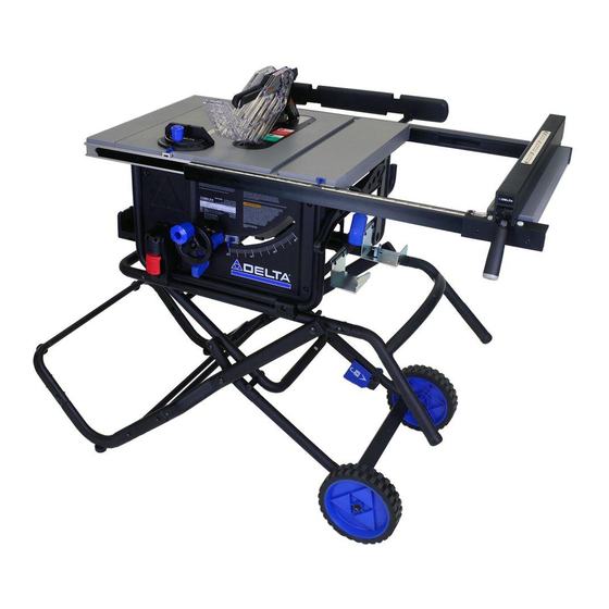
10-INCH PORTABLE CONTRACTOR
TABLE SAW
SCIE SUR TABLE PORTABLE CONTRACTOR DE 10 PO
SIERRA DE MESA DE CONTRATISTA PORTÁTIL DE 10
PULGADAS
Français (36)
Español (70)
www.DeltaMachinery.com
Instruction Manual
To reduce the risk of serious injury, thoroughly read and comply with all warnings and instructions in this manual and on product.
KEEP THIS MANUAL NEAR YOUR PRODUCT FOR EASY REFERENCE AND TO INSTRUCT OTHERS
36-6022
Advertisement
Table of Contents

Related Manuals for Delta 36-6022


Summary of Contents for Delta 36-6022
-
Page 1: Table Saw
Français (36) Español (70) www.DeltaMachinery.com 36-6022 Instruction Manual To reduce the risk of serious injury, thoroughly read and comply with all warnings and instructions in this manual and on product. KEEP THIS MANUAL NEAR YOUR PRODUCT FOR EASY REFERENCE AND TO INSTRUCT OTHERS... -
Page 2: Table Of Contents
OPERATION ................27 TURNING THE SAW ON/OFF ........... 28 FUNCTIONAL DESCRIPTION SPECIFICATIONS The DELTA® #36-6022 series 10-inch Contractor Table Saw is designed for portability and high quality Max depth of cut at 90 degrees: 3-1/2” performance. It includes: basic machine, sturdy tubular steel stand, integral 2 1/2”... -
Page 3: Important Safety Instructions
IMPORTANT SAFETY INSTRUCTIONS CAREFULLY READ AND FOLLOW ALL WARNINGS AND INSTRUCTIONS ON YOUR PRODUCT AND IN THIS MANUAL. SAVE THIS MANUAL. MAKE SURE ALL USERS ARE FAMILIAR WITH ITS WARNINGS AND INSTRUCTIONS WHEN USING THE TOOL. Improper operation, maintenance or modification of tools or equipment could result in serious injury and/or property damage. SAFETY SYMBOLS- DEFINITIONS This manual contains information that is important for you to know and understand. -
Page 4: Proposition 65 Warning
Wear protective clothing and wash exposed areas with soap and water If you have any questions or concerns relative to the use of your tool or the contents of this manual, stop using the tool and call DELTA® Customer Care at 1-800-223-7278. SAVE THESE INSTRUCTIONS. -
Page 5: Terminology
TABLE SAW SAFETY RULES TERMINOLOGY The following terms will be used throughout the manual and you should become familiar with them. — Through-cut - any cut that completely cuts through operator. the workpiece. — Freehand - cutting without the use of a miter gauge —... -
Page 6: Saw Blade Guard, Anti-Kickback Pawls And ....... Riving Knife Assembly
TABLE SAW SAFETY RULES are available at extra cost from your local dealer or risk of a thrown workpiece. authorized service center. • DO NOT REACH OVER/REACH AROUND. Never • DO NOT USE RIP FENCE AND MITER GAUGE AT reach over, in back of, or around the cutting tool with THE SAME TIME. -
Page 7: Kickbacks
TABLE SAW SAFETY RULES KICKBACKS Kickbacks can cause serious injury. A kickback occurs authorized service center for repair. when a part of the workpiece binds between the saw • Plastic and composite materials (like hardboard) may blade and the rip fence, or other fixed object, and rises be cut on your saw. -
Page 8: Power Connections
POWER CONNECTIONS POWER SOURCE This saw is equipped with a 15-amp motor for use with A separate electrical circuit should be used for your a 120-volt, 60-HZ alternating current. See instructions machines. This circuit should not be less than #12 wire below regarding proper connections for your saw. -
Page 9: Unpacking
Check shipping carton for damage before unpacking. missing, damaged or preassembled, do not assemble. Carefully remove components in top foam layer. Remove Instead call DELTA® Customer Care at 1-800-223-7278 the top layer of foam then remove all components in for assistance. -
Page 10: Contents Of Hardware Bags
UNPACKING CONTENTS OF HARDWARE BAGS aa. M6 x 30 Hex Bolt (4) hh. 5mm Allen Wrench (1) bb. M8 x 67 Carriage Screw (4) M6 x 20 Button Head Hex Socket Screw (2) cc. Plastic Spacer (8) Wheel Handle Shoulder Screw (1) dd. -
Page 11: Assembling Upper Stand
ASSEMBLY FIGURE 1 TUBE INSERTS SHOULDER ON BOTTOM TUBE INSERTS SHOULDER ON BOTTOM LOCK PIN FIGURE 2 ASSEMBLING UPPER STAND Assemble upper half (I1) of upper stand assembly to lower half (I2) of upper stand assembly as shown in Figure 1 using M8 x 75mm carriage screw (ee), spacer (cc) and M8 locknut (dd) to each side of upper stand assembly. -
Page 12: Assembling The Stand
ASSEMBLY FOOT PADS FIGURE 3 ASSEMBLING THE STAND Layout the left and right support rod assemblies (E & F). Place the cross connect assembly (H) between the support rod assemblies and connect the support rod connection tube (G) to the ends of the support rod assembly tubes as shown in Figure 3. NOTE: Ensure foot pads are oriented as shown in Figure 3. -
Page 13: Wheels
ASSEMBLY FIGURE 5 Secure the cross connect assembly (H) to the support rod assembly tubes using four M6 x 30 hex bolts. (aa) See Figure 5 & 5a. FIGURE 6 WHEELS Remove the lock nut and washer from each axle on the pedal assembly (D) as shown in Figure 6. -
Page 14: Pedal Assembly
ASSEMBLY FIGURE 7 Slide the wheels over axles and secure using the two washers and M8 lock nuts. See Figure 7. PEDAL ASSEMBLY Attach the pedal assembly (D) to the upper stand assembly using two M8 x 75 Carriage screws (ee), spacers (cc) and M8 lock nuts (dd). - Page 15 ASSEMBLY UPPER STAND ASSEMBLY SEE FIGURE FIGURE 9 Place the sides of the support rod assembly (E & F) so they are outside of the pedal assembly (D) and the feet are pointing down. See Figure 11 for correct position of the feet. Align the hole in the support rod assembly with the hole in the pedal assembly.
-
Page 16: Upper Stand Assembly
ASSEMBLY FEET FIGURE FIGURE 11 UPPER STAND ASSEMBLY Insert the stand handle (B) into the upper stand assembly as shown in Figure 12. Insert M8 x 35 carriage screw (ff) into the square hole at the end of the upper stand assembly (square hole at end of tube see Figure 12a) secure carriage screw (ff) with M8 Locknut (dd). - Page 17 ASSEMBLY UPPER STAND ASSEMBLY FIGURE 13 Attach the right and left support rod assemblies (E & F)as shown in Figure 13 to the upper stand assembly with two M8 x 67 carriage screws (bb), spacer (cc) and M8 locknuts (dd) as shown in Figures 13 & 14. NOTE: Ensure the spacer (cc) is between the support rod assembly and the upper stand assembly as shown in Figure NOTE: Make sure all hardware is tight but not overtight.
-
Page 18: Attach Saw To Stand Assembly
ASSEMBLY FIGURE 15 ATTACH SAW TO STAND ASSEMBLY Unlock the bevel lock tilt and rotate the motor assembly enough to remove the shipping foam protecting the saw motor as shown in Figure 15. Do NOT turn the handwheel during this step. STAND ASSEMBLY FIGURE 16... -
Page 19: Height Adjustment Knob Installation
ASSEMBLY FIGURE 17 Height Adjustment Knob Installation 1. Insert wheel handle shoulder screw (jj) into height adjustment wheel knob (kk) as shown in Figure. 17. 2. Tighten shoulder screw with Phillips Screw Driver into the Hand Wheel. Height adjustment wheel knob should rotate freely around shoulder screw when raising or lowering the blade with the Height Adjustment Hand Wheel. - Page 20 ASSEMBLY TOOTH DIRECTION FRONT OF ARBOR SHAFT FIGURE 19 FIGURE 20 Place blade (K) on the arbor shaft with the teeth on the blade pointing toward the front of the saw. Place flanged washer on the shaft with the large side of the washer against the blade, then secure blade assembly with nut. (Figure. 19) Tighten nut with blade wrenches (a).
-
Page 21: Insert Throat Plate
ASSEMBLY RIVING KNIFE THRU CUT POSITION LOCK POSITION FIGURE 21 WEAR PLATE FIGURE 22 To reduce the risk of serious injury, • the riving knife must be installed for every through cut and for every non-through cut unless the riving knife would interfere with the cut. - Page 22 ASSEMBLY FIGURE 23 SCREW UNDER THROAT PLATE FIGURE 24 Level the throat plate to the table top using (4) flat head screws. See Figure 23 and 24. For more details about leveling throat plate, see page 29. NOTE: There is a fifth flat head screw under the throat plate that is adjusted to provide support under the wear plate. Adjust this screw as needed to provide support.
-
Page 23: Anti-Kickbacks Pawls And Blade Guard
ASSEMBLY PRESS RIVING KNIFE FIGURE 25 LOCK SUPPORT ARMS FIGURE 26 FIGURE 27 Anti-Kickback Pawls and Blade Guard Press spring loaded pin on the right side of the anti-kickback pawl assembly (N) insert over the middle slot on the riving knife. -
Page 24: Outfeed Support Stops
ASSEMBLY FIGURE 28 Outfeed Support Stops Refer to Figure 28. Extend the rear table support to expose the two holes. Insert an M6 x 20 button head hex socket screw (ii) from underneath, tighten with the supplied allen wrench. Repeat on other side of outfeed suport. FIGURE 29 Assemble handle (mm) to fence assembly (J) as shown in Figure 29. - Page 25 ASSEMBLY LOCKED POSITION FIGURE 30 Position the T-square fence (J) over the front and rear rails. Ensure the fence lock is in the unlocked (up) position. Lower T-square fence (J) on to both front and rear rails. Position T-square fence (J) on the table as desired and lock into place.
-
Page 26: Onboard Storage
ASSEMBLY CORD WRAP FIGURE 31 FIGURE 32 NOTE: Prior to placing the rip fence in the storage position you must temporally remove the miter gauge from the storage position. ON-BOARD STORAGE Storage is located on the left panel, right panel and back side of the tool as shown in Figures 31 & 32. b. -
Page 27: Operation
1. Each time you use the saw, run through the recommended by DELTA® Power Equipment following checklist: Corporation may result in injury. -
Page 28: Turning The Saw On/Off
OPERATION LOCK FIGURE 33 TURNING THE SAW ON AND OFF The ON/OFF paddle switch is located on the left side of the front panel of the saw. To turn the saw ON lift the switch. Press the switch down to turn the saw OFF. When not in use, the saw should be turned off and the power switch locked out to prevent unauthorized use. -
Page 29: Making Cuts
MAKING CUTS Failure to comply with the following or operating the saw, always inspect the blade guard warnings may result in serious assembly and riving knife for proper alignment and personal injury. clearance with the saw blade. Check alignment after each change of beveling angle. -
Page 30: Rip Cuts
MAKING CUTS RIP CUTS 1. Remove miter gauge. 12. Use the push stick and any other cutting aids, as needed, to hold the workpiece against the table and 2. Make sure bevel angle is set to 0º. fence, and push the workpiece past the blade. A 3. -
Page 31: Crosscutting
MAKING CUTS (CONTINUED) CROSSCUTTING 7. Make sure the workpiece is clear of the blade - at least 1 inch or 25mm away - before starting the saw. • NEVER use the fence as a guide or length stop 8. Turn saw on. when crosscutting, unless you are using the fence as 9. -
Page 32: Compound Miter Cuts
MAKING CUTS (CONTINUED) COMPOUND MITER CUTS This is a combination of bevel crosscutting and mitering. Refer to Figure 40 and follow the instructions for both bevel crosscutting and mitering. Remember to use the right miter slot on the right side of the blade for all bevel cuts. -
Page 33: Making A Dado Cut
MAKING CUTS MAKING A DADO CUT Dado blades are stacked blades that can be used when making non-through cuts including through cut slots. Dado blades require a special throat plate. Dado blades and throat plates are all sold separately. • Carefully follow the instructions accompanying the dado blade for proper installation, set up and operation. -
Page 34: Auxiliary Miter Gauge Facing
CUTTING AIDS AND ACCESSORIES (CONTINUED) AUXILIARY MITER GAUGE FACING An auxiliary miter gauge facing is used to increase the surface area of the miter gauge face. If desired, you can fit the miter gauge with an auxiliary wood facing that should be at least 1-inch (25mm) higher than the maximum depth of cut, and at least as wide as the miter gauge. -
Page 35: Featherboard
CUTTING AIDS AND ACCESSORIES (CONTINUED) FEATHERBOARD Featherboards are used to keep the workpiece in contact 1. Select a solid piece of lumber approximately 3/4-inch with the fence and table (Figure 45), and help prevent thick, 2 1/2-inches wide and 12-inches long. kickback. -
Page 36: Making Adjustments
MAKING ADJUSTMENTS SCREW UNDER THROAT PLATE FIGURE 47 LEVELING THE THROAT PLATE The front, rear and sides of the throat plate must be level with the surface of the table. There are four screws pre-assembled to the table that are used to level the throat plate. If the throat plate is not flush with the surface of the table, adjust these screws to ensure the entire throat plate is flush with the table. -
Page 37: Adjusting The Bevel Stops
MAKING ADJUSTMENTS 45° UNLOCK LOCK FIGURE. FIGURE 49 0° UNLOCK LOCK FIGURE. FIGURE 50 ADJUSTING THE BEVEL STOPS If the blade is not vertically square with the table, you must adjust the 0-degree positive stop located on the inside of the bevel track at the left end of the bevel track opening as shown in Figures 50 and 50a. -
Page 38: Adjusting The Blade Height
MAKING ADJUSTMENTS ADJUSTMENT WHEEL UNLOCK LOCKING LEVER LOCK FIGURE 51 ADJUSTING THE BLADE HEIGHT For all through cuts, the top of the blade points should be above the workpiece and the bottom of the blade gullets are below the top surface of workpiece. For non-through cuts, the top of the blade points should be set to the depth of the cut. -
Page 39: Using The Miter Gauge
MAKING ADJUSTMENTS LOCK KNOB FIGURE 52 USING THE MITER GAUGE There are two miter gauge grooves. one on either side of the blade. When making a 90º cross cut, use either groove. For beveled cross cut use the groove on right so that the blade is tilted away from miter gauge and hands. Loosen the miter gauge lock knob. -
Page 40: Using The Right Hand Table Extension
MAKING ADJUSTMENTS POINTER UNLOCK EXTENSION TABLE LOCK FIGURE 54 USING THE RIGHT HAND TABLE EXTENSION The table extension, located on the right side of the table, enables you to increase the width of the saw table to accommodate oversized workpieces. To use the table extension, refer to Figure 54 and do the following: Release the table extension lock (B) by moving it up. - Page 41 MAKING ADJUSTMENTS FIGURE 56 To adjust the rip fence so it is perpendicular to the table, make adjustments to the nylons screws on the top of the rip fence “T” as shown in Figure 56. FIGURE 57 To make adjustments to clamping pressure for rip fence, adjust screw on back of fence to the right to tighten and to the left to loosen clamping pressure.
-
Page 42: Riving Knife Position And Alignment
RIVING KNIFE POSITION AND ALIGNMENT UNLOCK LOCK FIGURE 58 LOWERING THE RIVING KNIFE Remove throat plate. 1. With the blade assembly to the highest possible position, carefully reach alongside the blade and raise the riving knife locking lever up to unlock the riving knife. 2. -
Page 43: Riving Knife Alignment
RIVING KNIFE POSITION AND ALIGNMENT NON-THRU THRU-CUT FIGURE 59 Location point for NON-THRU CUT POSITION NOTE: Riving knife is located in this position for “NON-THRU” cuts and is also in this position when packaged for shipment. Location point for THRU CUT POSITION as shown in Figure 59. (Operator should adjust the riving knife to this position when making “THRU”... - Page 44 RIVING KNIFE POSITION AND ALIGNMENT FIGURE 61 Horizontal Alignment The plane of the riving knife appears to be twisted in comparison to the plane of the blade. (Can be seen looking straight down on the blade and riving knife.) If the riving knife has horizontal misalignment, adjust as follows using Figure 59 and Figure 61. 1.
-
Page 45: Maintenance
RIVING KNIFE CLAMP PLATE: Keep this area free of dust and debris buildup. Blow out area regularly with compressed air. NOTE: If the riving knife clamp can’t move freely, have the saw serviced by authorized DELTA® Power Equipment Corporation service center personnel. -
Page 46: Warranty
® ® normal use has proven to be defective in workmanship or material, provided that the customer returns the product prepaid to a DELTA ® factory service center or authorized service station with proof of purchase of the product within five years and provides DELTA with ®... -
Page 47: French
2651 New Cut Road Spartanburg, SC 29303 (800) 223-7278 www.DeltaMachinery.com ® Copyright © 2016 DELTA Power Equipment Corporation DPEC004331 - 03-28-16 Rev Date: 06-06-16...