Table of Contents
Advertisement
Advertisement
Table of Contents

Related Manuals for Delta 36-600


Summary of Contents for Delta 36-600
- Page 1 10" Table Saw (Model 36-600) PART NO. 901608 (014) Copyright © 2001 Delta Machinery To learn more about DELTA MACHINERY ESPAÑOL: PÁGINA 29 visit our website at: www.deltamachinery.com. For Parts, Service, Warranty or other Assistance, 1-800-223-7278 ( 1-800-463-3582). please call...
-
Page 2: Safety Rules
Woodworking can be dangerous if safe and proper operating procedures are not followed. As with all machinery, there are certain hazards involved with the operation of the product. Using the machine with respect and caution will considerably lessen the possibility of personal injury. However, if normal safety precautions are overlooked or ignored, personal injury to the operator may result. -
Page 3: Additional Safety Rules For Table Saws
15. DO NOT feed the material too fast while cutting. Feed the material only fast enough so that the blade will cut. 16. NEVER attempt to free a stalled saw blade without first turning the saw “OFF.” 17. NEVER start the saw with the workpiece pressed against the blade. -
Page 4: Power Connections
CONNECTING TOOL TO POWER SOURCE A separate electrical circuit should be used for your tools. This circuit should not be less than #12 wire and should be protected with a 20 Amp time lag fuse. If an extension cord is used, use only 3-wire extension cords which have 3- prong grounding type plugs and 3-hole receptacles which accept the tool’s plug. -
Page 5: Extension Cords
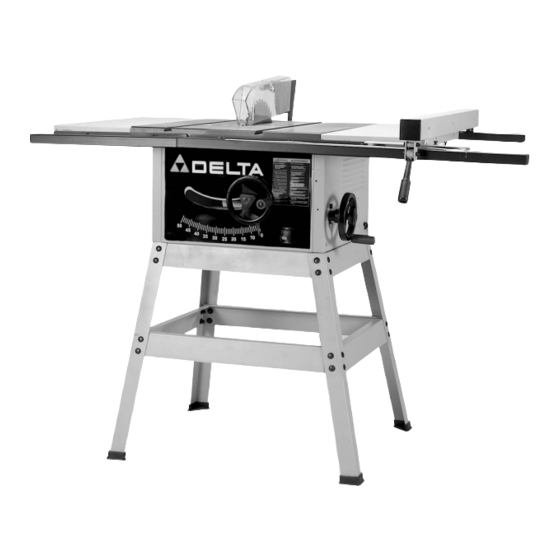
Delta Model 36-600 is a 10" Table Saw designed to give high quality performance with maximum depth of cut capacity up to 3-1/8" 79mm at 90° and 2-1/8" (54mm) at 45° for clean cutting of standard stock sizes. Delta Model 36-600 includes;... -
Page 6: Unpacking And Cleaning
(do not use acetone, gasoline or lacquer thinner for this purpose). After cleaning, cover the table surface with a good quality household floor paste wax. Figs. 1 and 2 illustrate the components and hardware for the table saw. Fig. 3 illustrates the components of the stand. - Page 7 11 - M6.4 Flat Washer (5) 12 - M6.1 Lockwasher (5) 13 - M6 Hex Nut (5) Fig. 2 For Fastening Saw to Stand 14 - M8 x 16MM Hex Head Screws (4) 15 - 3/8″ Flat Washer (8) 16 - M8 Hex Nut (4)
- Page 8 Fig. 3 For Saw Stand 1 - Top Front and Rear Braces - 19″ in length (2) 2 - Bottom Front and Rear Braces - 22-1/2″ in length (2) 3 - Stand Legs (4) 4 - Plastic Feet (4) 5 - 3/8″ Flat Washer (32)
-
Page 9: Assembling Saw To Stand
ASSEMBLING SAW TO STAND 1. Position the saw (B) on the stand as shown in Fig. 6, lining up the four holes on the bottom of sides of the saw cabinet with the four holes in the two top side braces, one of which is shown at (A). - Page 10 Fig. 8. ASSEMBLING EXTENSION WINGS 1. Assemble extension wing (A) Fig. 9, to the saw table using the three 16MM screws, lockwashers, and flat washers (B). With a straight edge (C) Fig. 10, make sure the extension wing is level with the saw table before tightening the three screws (B) Fig.
-
Page 11: Assembling Saw Blade
Fig. 11. IMPORTANT: Be careful not to lose two rubber washers (L) located under table insert (A). 3. Raise the saw blade arbor (B) Fig. 11, to its maximum height by turning the blade raising handwheel counterclockwise and remove the arbor nut (E) (turn clockwise) and outer flange (D) from the saw arbor. - Page 12 GUIDE RAILS 1. Align the three slotted holes in the front guide rail (A) Fig. 14, with two holes (B) in saw table and slotted hole (C) in extension wing. Fasten front guide rail (A) Fig. 14 to table saw with three 20MM long carriage bolts (D), flat washers (E), lockwashers (F), and hex nuts (G) as shown assembled in Fig.
-
Page 13: Assembling Rip Fence
Working toward the two ends of the rear guide rail, make certain the rear guide rail is parallel to the saw table, at 7/16" from the top of the table. Tighten all mounting hardware as height adjustment is made to the rear guide rails. - Page 14 4. Using a square (H) Fig. 25 set at 13/16″, place the square on the saw table and against the top of guide rail (D). Align the guide rail until it is parallel to the saw table by loosening and tightening mounting hardware at five positions (K) Fig.
-
Page 15: Assembling Blade Guard And Splitter Assembly
(C) before tightening wing nut (E). 5. Check the alignment of the splitter (C) Fig. 29, to the saw blade using a straight edge as shown. If alignment is necessary, loosen nut (B), align splitter (C) and retighten nut (B). -
Page 16: Operating Controls And Adjustments
OPERATING CONTROLS AND ADJUSTMENTS STARTING AND STOPPING SAW The switch (A) is located on the front panel of the saw cabinet, as shown in Fig. 33. To turn the saw “ON” move the switch to the up position. To turn the saw “OFF”... -
Page 17: Adjusting 90 And 45 Degree Positive Stops
ADJUSTING 90 AND 45 DEGREE POSITIVE STOPS Your saw is equipped with positive stops that will position the saw blade at 90 and 45 degrees to the table. To check and adjust the positive stops, proceed as follows: Fig. 36 1. -
Page 18: Rip Fence Operation And Adjustments
RIP FENCE OPERATION AND ADJUSTMENTS IMPORTANT: THE RIP FENCE MUST BE PROPERLY ALIGNED TO THE MITER GAGE SLOT IN ORDER TO PREVENT KICKBACK WHEN RIPPING. 1. To move the fence (A) Fig. 41, along the guide rails, lift up on the fence locking lever (B), slide the fence to the desired location on the guide rails and push down on the locking lever (B) to lock the fence in position. -
Page 19: Adjusting Table Insert
(F) rides in the T-slotted miter gage slot (J) and prevents the miter gage from falling when it is extended out beyond the front of the saw table, as shown in Fig. ADJUSTING TABLE INSERT The table insert (A) Fig. 47, should be adjusted so it is flush with the saw table surface. - Page 20 Start the cut slowly and hold the work firmly against the miter gage and the table. One of the rules in running a saw is that you never hang onto or touch a free piece of work. Hold the supported piece, not the free piece that is cut off.
-
Page 21: Using Accessory Moulding Cutterhead
Moulding is cutting a shape on the edge or face of the work. Cutting mouldings with a moulding cutterhead in the circular saw is a fast, safe and clean operation. The many different knife shapes available make it possible for... -
Page 22: Using Accessory Dado Head
Fig. 55. The saw and cutter overlap is shown in Fig. 56, (A) being the outside saw, (B) an inside cutter, and (C) a paper washer or washers which can be used as needed to control the exact width of groove. -
Page 23: Constructing A Featherboard
A wood facing should be used when ripping thin material such as paneling to prevent the material from catching between the bottom of the rip fence and the saw table surface. At a slight charge, further information on the safe and proper operation of table saws is available in the Delta “Getting the Most Out of Your Table Saw”... -
Page 24: Constructing A Push Stick
CONSTRUCTING A PUSH STICK When ripping work less than 4 inches wide, a push stick should be used to complete the feed and could easily be made from scrap material by following the pattern shown in Fig. 61. -
Page 25: Changing The Blade
(A) Fig. 62. NOTE: Be careful not to lose two rubber washers (E). 3. Using the open end wrench (B) Fig. 62, place wrench on flats on saw arbor and remove arbor nut (C) using wrench (D) by turning nut clockwise. Remove blade flange and saw blade. -
Page 26: Belt Replacement
Tilt the arbor to the 45 degree tilt position. 3. Turn the saw upside down and place it on a flat non- scratch surface. 4. Remove the four screws (A) Fig. 65, and cover (B) from the end of the motor housing. - Page 27 A complete line of accessories is available from your Delta Supplier, Porter-Cable · Delta Factory Service Centers, and Delta Authorized Service Stations. Please visit our Web Site www.deltamachinery.com for a catalog or for the name of your nearest supplier. WARNING: Since accessories, other than those offered by Delta, have not been tested with this product, use of such accessories could be hazardous.
- Page 28 NOTES...
- Page 29 ® , TIGER CUB SAW™, MICRO-SET™, MORTEN™, NETWORK™, RIPTIDE™, TRU-MATCH™, WOODWORKER’S CHOICE™. Trademarks noted with ® are registered in the United States Patent and Trademark Office and may also be registered in other countries. Las Marcas Registradas con el signo de ® son registradas por la Oficina de Registros y Patentes de los Estados Unidos y también pueden estar registradas en otros países.