Table of Contents
Advertisement
Available languages
Available languages
Quick Links
Advertisement
Chapters
Table of Contents

Related Manuals for Delta 36-260


Summary of Contents for Delta 36-260
-
Page 2: Table Of Contents
TABLE OF CONTENTS SAFETY INFORMATION ..........2 ASSEMBLY ..............4 GENERAL SAFETY RULES .........2 Attaching saw to mounting brackets ....4 UNPACKING ..............3 TROUBLESHOOTING,SERVICE&ACCESSORIES ..7 Package Contents ..........3 WARRANTY ..............8 Hardware ..............3 IMPORTANT SAFETY INSTRUCTIONS CAREFULLY READ AND FOLLOW ALL WARNINGS AND INSTRUCTIONS ON YOUR PRODUCT AND IN THIS MANUAL. -
Page 3: Unpacking
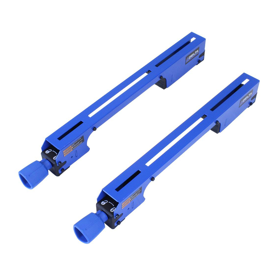
UNPACKING PACKAGE CONTENTS DESCRIPTION (QTY) • Miter Saw Stand Mounting Brackets (2) HARDWARE DESCRIPTION (QTY) • M8 x 55 mm Carriage Bolt (4) • M8 Washer (4) • M8 Hex Nut (4) -
Page 4: Assembly
ASSEMBLY ATTACHING SAW TO MOUNTING BRACKETS Make sure the saw is positioned for best balance and stability. All corners of the saw must be bolted securely to the mounting brackets before use. Make sure no bolts extend above the saw table. Note: Only 4 sets of securing hardware are provided with the stand. - Page 5 ASSEMBLY (continued) 3. Insert bolts (CC) through bracket and saw base. Place washers (DD) on bolts and secure with nuts (BB). FINGER TIGHTEN only. Repeat for other side. 4. Place saw and brackets (B) onto stand (D), hooking front of mounting brackets on fi rst. Adjust to center the table over the stand.
- Page 6 ASSEMBLY (continued) 5. Make sure the bracket knobs are turned to the locked position when correctly positioned on the stand and tighten the nuts on all four corners of the saw. Note: Make sure the saw is centered and balanced over stand rails.
- Page 7 Authorized Warranty Service Center, visit ACCESSORIES A complete line of accessories is available from your DELTA® Supplier, DELTA® Factory Service Centers and DELTA® Authorized Service Stations. Please visit our Web Site at www.DeltaMachinery.com for an online catalog or for the name of your nearest supplier.
-
Page 8: Warranty
WHAT IS COVERED. Delta Power Equipment Corporation (“Company”) will repair or replace, at its option, any new or factory refurbished DELTA®machine or service part which is purchased at retail in the United States or Canada and which normal use has proven to be defective in workmanship or material, subject to the conditions stated in this Limited Warranty. - Page 9 2651 New Cut Road Spartanburg, SC 29303...
- Page 10 Lisez attentivement et respectez tous les avertissements et instructions contenus dans ce manuel et sur le produit pour réduire le risque de blessures graves. 36-260 CONSERVEZ CE MANUEL A PORTÉE DE MAIN POUR POUVOIR FACILEMENT LE CONSULTER ET CONSEILLER LES AUTRES.
-
Page 11: Règles Générales De Sécurité
SOMMAIRE INSTRUCTIONS DE SÉCURITÉ ........2 MONTAGE ..............4 RÈGLES GÉNÉRALES DE SÉCURITÉ .......2 Attacher la scie aux supports de montage ..4 DÉBALLAGE ..............3 DÉPANNAGE, ENTRETIEN & ACCESSOIRES ....7 Contenu des cartons ..........3 GARANTIE ..............8 Quincaillerie ............3 INSTRUCTIONS DE SÉCURITÉ IMPORTANTES LISEZ AVEC SOIN TOUS LES AVERTISSEMENTS ET INSTRUCTIONS D'UTILISATION PRÉSENTS AVERTISSEMENT: SUR LE PRODUIT ET DANS CE MANUEL. -
Page 12: Déballage
DÉBALLAGE DESCRIPTION DU CONTENU DES CARTONS (QTÉ) • Supports de montage pour établi de scie à onglets (2) DESCRIPTION DE LA QUINCAILLERIE (QTÉ) • Boulon de carrossier M8x55mm (4) • Rondelle M8 (4) • Écrou hex. M8 (4) -
Page 13: Montage
MONTAGE ATTACHER LA SCIE AUX SUPPORTS DE MONTAGE Assurez-vous que la scie est stable et en équilibre. Les coins de la scie doivent tous être bien boulonnés aux supports de montage avant l’utilisation. Assurez-vous qu’aucun boulon ne dépasse le dessus de l’établi de scie. Note: Seuls 4 éléments de fi... - Page 14 MONTAGE (suite) 3. Insérez les boulons (CC) au travers du support et de la base de la scie. Placez les rondelles (DD) sur les boulons et fi xez le tout avec les écrous (BB). SERREZ AVEC LES DOIGTS seulement. Répétez de l’autre côté.
- Page 15 MONTAGE (suite) 5. Assurez-vous que les boutons des supports de fi xation sont en position de verrouillage lorsqu’ils sont bien en place sur le stand et serrer les écrous sur les quatre côtés de la scie. Note: Assurez-vous que la scie est centrée et en équilibre au dessus des rails du stand.
- Page 16 AVERTISSEMENT: Étant donné que les accessoires autres que ceux off erts par DELTA® n’ont pas été testés avec ce produit, leur utilisation pourrait s’avérer dangereuse. Pour plus de sûreté, utilisez seulement les...
-
Page 17: Garantie
COMMENT OBTENIR CE SERVICE. Pour obtenir le service de garantie, vous devez retourner le produit défectueux, à vos frais, à un centre de service agréé par la Société pour eff ectuer le service de garantie (un “centre de service agréé par DELTA®”) pendant la période de garantie applicable, avec une preuve d’achat acceptable, tel le reçu original portant la date d’achat, ou le numéro d’enregistrement du produit. - Page 18 2651 New Cut Road Spartanburg, SC 29303 (800) 223-7278 www.DeltaMachinery.com Copyright © 2015 DELTA Power Equipment Corporation DPEC003862 ®...
- Page 19 Para reducir el riesgo de heridas graves, lea completamente este manual y cumpla todos los avisos e instrucciones que haya en el mismo y en el producto. 36-260 MANTENGA ESTE MANUAL CERCA DE SU PUESTO COMO REFERENCIA DE FÁCIL ACCESO Y PARA INSTRUIR A OTROS.
-
Page 20: Normas Generales De Seguridad
TABLA DE CONTENIDO INFORMACIÓN DE SEGURIDAD ........2 ENSAMBLAJE ...............4 NORMAS GENERALES DE SEGURIDAD ....2 Acoplar la sierra a las abrazaderas ......4 DESEMBALADO ............3 SOLUCIÓN DE PROBLEMAS, MANTENIMIENTO Y Contenido de la caja ..........3 ACCESORIOS..............7 Ferretería ..............3 GARANTÍA ..............8 INSTRUCCIONES IMPORTANTES DE SEGURIDAD LEA ATENTAMENTE Y SIGA TODOS LOS AVISOS E INSTRUCCIONES EN SU PRODUCTO Y EN ADVERTENCIA: ESTE MANUAL. - Page 21 DESEMBALAJE DESCRIPCIÓN DEL CONTENIDO DE LA CAJA (CANT) • Abrazaderas de montaje para la base de la sierra ingletadora (2) ACCESORIOS DE FERRETERÍA (CANT) • Perno de carruaje M8 x 55 mm (4) • Arandela M8 (4) • Tuerca hexagonal M8 (4)
-
Page 22: Ensamblaje
ENSAMBLAJE ACOPLAR LA SIERRA A LAS ABRAZADERAS DE MONTAJE Asegúrese que la sierra está situada para tener el máximo equilibrio y estabilidad. Todas las esquinas de la sierra deben estar seguramente atornilladas a las abrazaderas antes de su uso. Asegúrese que ningún perno sobresale por encima de la mesa de la sierra. - Page 23 ENSAMBLAJE (continuación) 3. Inserte los pernos (CC) a través de la abrazadera y la base de la sierra. Coloque las arandelas (DD) en los pernos y asegúrelas con las tuercas (BB).APRIETE sólo CON LOS DEDOS. Repita para el otro lado. 4.
- Page 24 ENSAMBLAJE (continuación) 5. Asegúrese que las manijas de las abrazaderas están giradas en la posición de bloqueo cuando estén colocadas en la base, y apriete las tuercas de las cuatro esquinas de la sierra. Nota: Asegúrese que la sierra está centrada y equilibrada sobre las guías de la base.
-
Page 25: Accesorios
SOLUCIÓN DE PROBLEMAS Para recibir asistencia relativa a su producto, visite nuestro sitio web en www.DeltaMachinery.com para ver una lista de centros de servicio o llame a la línea de atención al cliente DELTA ® Power Equipment Corporation al 1-800-223-7278. MANTENIMIENTO PIEZAS DE RECAMBIO Servicio en Garantía, visite nuestro sitio web en www. -
Page 26: Garantía
QUÉ ESTÁ CUBIERTO. Delta Power Equipment Corporation (“Compañía”) reparará o reemplazará, a su discreción, cualquier máquina o pieza nueva o restaurada en fábrica DELTA® que haya sido adquirida en los Estados Unidos de América o Canadá y que haya resultado defectuosa en material o mano de obra bajo un uso normal, de acuerdo a las condiciones indicadas en esta garantía limitada. - Page 27 2651 New Cut Road Spartanburg, SC 29303 (800) 223-7278 www.DeltaMachinery.com Copyright © 2015 DELTA Power Equipment Corporation DPEC003862 ® Revised: 3/1/2016...