Table of Contents
Advertisement
Advertisement
Table of Contents

Related Manuals for Delta 36-650


Summary of Contents for Delta 36-650
- Page 1 10" Professional Table Saw (Model 36-650) PART NO. 902113 - 11-22-02 Copyright © 2002 Delta Machinery To learn more about DELTA MACHINERY visit our website at: www.deltamachinery.com. For Parts, Service, Warranty or other Assistance, 1-800-223-7278 ( 1-800-463-3582). please call In Canada call...
-
Page 2: General Safety Rules
If you have any questions relative to a particular application, DO NOT use the machine until you have first contacted Delta to determine if it can or should be performed on the product. -
Page 3: Table Saws
KICKBACK FINGERS except when otherwise directed in the manual. 7. REMOVE CUT-OFF PIECES AND SCRAPS from the table before starting the saw. The vibration of the machine may cause them to move into the saw blade and be thrown out. After cutting, turn the machine off. -
Page 4: Power Connections
3. 240 VOLT SINGLE PHASE OPERATION: The motor supplied with your saw is a dual voltage, 120/240 volt motor. If it is desired to operate your saw at 240 volts, single phase, it is necessary to reconnect the motor leads in the motor junction box by following the in- structions given on the motor nameplate. -
Page 5: Extension Cords
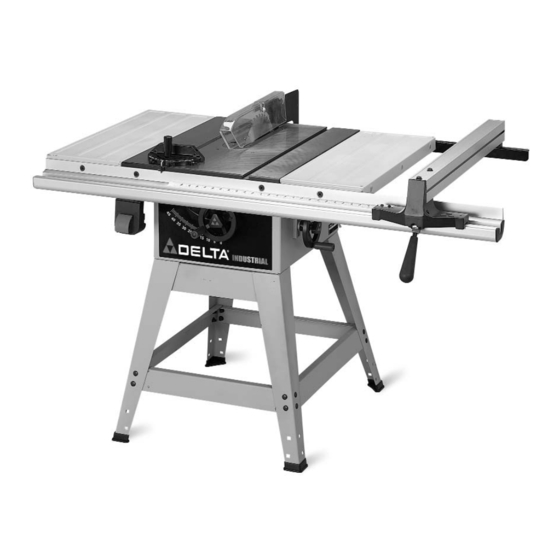
FOREWORD Delta Model 36-650 is a 10" professional table saw. The Model 36-650 has a powerful 1½ HP induction motor which can handle tough cutting operations. The Model 36-650 comes with a heavy duty fence system with a 30" rip capacity to the right of the blade. - Page 6 10" PROFESSIONAL TABLE SAW PARTS 1. Table Saw 2. Extension Wing (2) 3. Motor 4. Pulley Guard Plate 5. Switch Assembly 6. Lock Knob (2) 7. Handwheel (2) 8. Miter Gage Handle 9. Motor Plate 10. Motor Pulley 1. Guide Rail 2.
- Page 7 1. Leg (4) 2. Bracket 24" Long (2) 3. Bracket 21" Long (2) 4. Top Bracket (1) 5. Plastic Foot (4) 1. 7/16-20x3/4" Hex Head Screw (6) 2. 3/8-16x1½" Flat Head Screw (4) 3. 3/8-16x1" Hex Head Screw (4) 4. 5/16-18x3/4" Carriage Head Screw (4) 5.
- Page 8 FLOOR, SUCH AS A PIECE OF CARDBOARD, CARPET ETC. NOTE: Make certain the shorter stand brackets (D) Fig. 8, are at the front and rear of the saw as shown. 2. Align the eight holes in the bottom of the saw cabinet with the eight holes in stand legs.
- Page 9 CAREFULLY TURN THE SAW AND STAND UPRIGHT AS SHOWN IN FIG. 10. Carefully push down on the top of the saw until the stand legs adapt to the floor surface and firmly tighten all stand mounting hardware. BLADE TILTING AND RAISING HANDWHEEL 1.
- Page 10 2. Insert switch cord (A) Fig. 14, and motor cord (B) into clamps (D) and loosely fasten both cords (A) and (B) Fig. 15, to the saw cabinet by turning screws (E) Fig. 14, clockwise. NOTE: Cords will be adjusted later. Place switch on top of the saw table at this time.
- Page 11 (A) until pins (X) are engaged in holes (D) Fig. 17, of motor mounting plate (A). 5. Fig. 19, illustrates the motor and motor mounting plate assembled to the rear of the saw. Fig. 16 Fig. 17 Fig. 18...
- Page 12 MOTOR PULLEY, PULLEY GUARD, AND DRIVE BELT DISCONNECT MACHINE FROM POWER SOURCE. 1. Remove the motor shaft key that is taped to the motor. 2. Insert key (A) Fig. 20, in the keyway on the motor shaft. Assemble motor pulley (B) on motor shaft as shown, with the hub of the pulley out.
- Page 13 IMMEDIATELY AFTER ASSEMBLING THE BELT, RAISE THE SAW BLADE TO ITS MAXIMUM HEIGHT AND TILT THE SAW BLADE TO 45 DEGREES. USING A STRAIGHT EDGE (L) FIG. 25, CHECK TO SEE IF THE MOTOR END (J) FIG. 25, IS BELOW THE TOP OF THE TABLE SURFACE (K).
- Page 14 Repeat this process for the remaining hole. Do not completely tighten the two screws (B) at this time. 2. Raise saw arbor to its highest position. 3. Remove screw and large washer (C) Fig. 30, from the inside splitter mounting bracket.
- Page 15 (L) of splitter (G); the blade guard will stay in this position. 9. With the blade guard (L) Fig. 36, in the raised position, assemble the saw blade (K) on the saw arbor with two arbor wrenches supplied. Fig. 33 Fig.
-
Page 16: Extension Wings
10. Using a straight edge, check to see if the saw blade is aligned with the rear of the splitter (G), as shown in Fig. 37. If alignment is necessary, loosen the screws (A) Fig. 37, align splitter (G) with the saw blade, and tighten two screws (A). - Page 17 SWITCH ASSEMBLY 1. Loosely assemble front guide rail (A) Fig. 40, to the front of the saw table. Align the two holes (B) and (C) with the two holes in the saw table. Insert a 3/8-16x1- 1/2" flat head screw (F) Fig. 40, through holes (B) and (C) in the front guide rail (A) and the holes in the front of the saw table.
- Page 18 6. Once the rip fence is aligned with the miter gage slot, raise the saw blade (E) Fig. 48, to its highest position, as shown. Slide rip fence (B) against the saw blade (E) and lock the fence in that position by pushing down on handle (A).
- Page 19 STARTING AND STOPPING SAW 1. The on/off switch is located underneath the switch shield (A) Fig. 54. To turn the saw “ON,” move switch trigger (B) to the up position. 2. To turn the saw “OFF,” push down on switch shield (A) Fig.
-
Page 20: Raising And Lowering The Blade
RAISING AND LOWERING THE BLADE To raise the saw blade, loosen lock knob (A) Fig. 58, and turn the blade raising handwheel (B) clockwise. When the blade is at the desired height, tighten lock knob (A). To lower the blade, loosen lock knob (A) Fig. 58, and turn the handwheel (B) counterclockwise. - Page 21 (C). RIP FENCE OPERATION AND ADJUSTMENTS The rip fence can be used on either side of the saw blade. The most common location is on the right side and is guided by means of guide rails which are fastened to the front and rear of the table.
- Page 22 5. Depending on the type of saw blade being used, the cursor (D) Fig. 64, may need adjustment to compensate for the blade thickness.To adjust the cursor, make a test cut on a piece of lumber and measure the finished cut, or you can place the rip fence against the blade as shown earlier in the manual.
-
Page 23: Overload Protection
DISCONNECT MACHINE FROM POWER SOURCE. 1. NOTE: Two 7/8" wrenches are supplied with the saw for changing the saw blade: a box end wrench (A) Fig. 69, and open end wrench (B). 2. Remove table insert (C) Fig. 69, and raise saw blade to its maximum height. - Page 24 The following information describes the safe and proper method for performing the most common sawing operations. THE USE OF ATTACHMENTS AND ACCESSORIES NOT RECOMMENDED BY DELTA MAY RESULT IN THE RISK OF INJURY TO PERSONS.
- Page 25 When ripping boards longer than three feet, it is recommended that a work support be used at the rear of the saw to keep the workpiece from falling off the saw table.
- Page 26 Loosen screws (G) and (H) Fig. 85. Lift up and swing blade guard and splitter assembly (W) Fig. 86, to the rear of the saw, and then tighten screws (G) and (H). Always return and fasten the blade guard and splitter assembly to its proper operating position for normal thru-sawing operations.
- Page 27 Fig. 90. The saw and cutter overlap is shown in Fig. 91, (A) being the outside saw, (B) an inside cutter, and (C) a paper washer or washers which can be used as needed to control the exact width of groove.
-
Page 28: Constructing A Featherboard
CONSTRUCTING A FEATHERBOARD Fig. 95, illustrates dimensions for making a typical featherboard. The material which the featherboard is constructed of, should be a straight piece of wood that is free of knots and cracks. -
Page 29: Constructing A Push Stick
CONSTRUCTING A PUSH STICK When ripping work less than 4 inches wide, a push stick should be used to complete the feed and could easily be made from scrap material by following the pattern shown. - Page 30 1-800-223-7278 (In Canada call 1-800-463-3582). Delta will repair or replace, at its expense and at its option, any Delta machine, machine part, or machine accessory which in normal use has proven to be defective in workmanship or material, provided that the customer returns the product prepaid to a Delta factory service center or authorized service station with proof of purchase of the product within two years and provides Delta with reasonable opportunity to verify the alleged defect by inspection.
- Page 31 NOTES...
- Page 32 Delta products should be obtained by contacting any Porter-Cable · Service Center, or Porter-Cable Delta Factory Service Center. If you do not have access to any of these, call 800-223-7278 and you will · be directed to the nearest Porter-Cable Delta Factory Service Center.