Table of Contents
Advertisement
Advertisement
Table of Contents

Related Manuals for Delta 36-729


Summary of Contents for Delta 36-729
- Page 1 10" Cabinet Saw (Model 36-729) PART NO. 911972 - 06-15-05 Copyright © 2005 Delta Machinery To learn more about DELTA MACHINERY visit our website at: www.deltamachinery.com. For Parts, Service, Warranty or other Assistance, 1-800-223-7278 ( 1-800-463-3582). please call In Canada call...
-
Page 2: Table Of Contents
IMPORTANT SAFETY INSTRUCTIONS ............2 SAFETY GUIDELINES . -
Page 3: Safety Guidelines
SAFETY GUIDELINES - DEFINITIONS It is important for you to read and understand this manual. The information it contains relates to protecting YOUR SAFETY and PREVENTING PROBLEMS. The symbols below are used to help you recognize this information. Indicates an imminently hazardous situation which, if not avoided, will result in death or serious injury. Indicates a potentially hazardous situation which, if not avoided, could result in death or serious injury. -
Page 4: General Safety Rules
GENERAL SAFETY RULES FAILURE TO FOLLOW THESE RULES MAY RESULT IN SERIOUS INJURY. 1. FOR YOUR OWN SAFETY, READ THE INSTRUCTION MANUAL BEFORE OPERATING THE MACHINE. Learning the machine’s application, limitations, and specific hazards will greatly minimize the possibility of accidents and injury. 2. -
Page 5: Additional Specific Safety Rules
15. NEVER have any part of your body in line with the path of the saw blade. 16. NEVER REACH AROUND or over the saw blade. 17. NEVER attempt to free a stalled saw blade without first turning the machine “OFF”. 18. PROPERLY SUPPORT LONG OR WIDE workpieces. -
Page 6: Power Connections
DO NOT EXPOSE THE MACHINE TO RAIN OR OPERATE THE MACHINE IN DAMP LOCATIONS. MOTOR SPECIFICATIONS The 36-729 Unisaw has a 240 volt single phase motor rated for three horsepower and 60 HZ alternating current. Before connecting the machine to the power source, make sure the switch is in the “OFF” position. -
Page 7: Functional Description
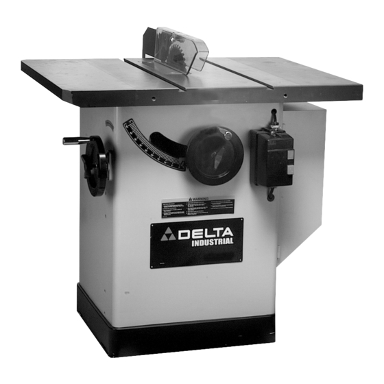
FUNCTIONAL DESCRIPTION FOREWORD Delta Model 36-729 is a 10" cabinet saw. The cabinet saw has a powerful 3 H.P. motor, and a large 36" x 27" cast-iron table with extension wings. NOTICE: THE PHOTO ON THE MANUAL COVER ILLUSTRATES THE CURRENT PRODUCTION MODEL. -
Page 8: Assembly
1. Saw 2. M10x1.5x35mm Hex Head Bolt (6) 3. M10 Flat Washer (6) 4. M10.1 Lockwasher (6) 5. Left Side Extension Wing 6. Miter Gage 7. Motor Cover 8. Blade Guard / Splitter Assembly 9. Right Side Extension Wing ASSEMBLY TOOLS REQUIRED * 1/8"... -
Page 9: Extension Wings
OR SLIGHTLY BEHIND THE FRONT EDGE OF THE TABLE. Use a straight edge (C) Fig. 7, to make sure the extension wing (A) is level with the saw table before tightening the screws (B) Fig. 6 with a 17mm wrench. - Page 10 “CHANGING THE SAW BLADE”. 2. The inside splitter mounting bracket (A) Fig. 9, is assembled to the inside of the saw and aligned with the inside blade flange (B) at the factory. 3. To check the alignment, remove screw and fastener plate (C) Fig.
- Page 11 Fig. 12 5. Insert threaded end of support rod / splitter bracket (G) Fig. 12, through slot in rear of saw and into hole in rear trunnion (H). Fasten support rod / splitter bracket (G) to trunnion with a M12.1 washer and M12x1.75 hex jam nut (J) Fig.
- Page 12 (X). With an 8mm hex wrench (Y) inserted in the hex hole in the arbor to keep it from turning, tighten arbor nut by turning box end wrench (Z) to the rear of the saw. 11. Using a straight edge (A) Fig. 21, make certain the splitter (P) is aligned with the saw blade (B).
-
Page 13: Motor Cover
12. Holding the clear blade guard, lower the saw blade and assemble the table insert (E) Fig. 24, into the open- ing on the saw table. Tighten screw (F) to fasten the table insert to the saw. 13. Place a straight edge (B) across the table at both ends of the table insert as shown in Fig. -
Page 14: Operation
(A), clockwise. To lower the saw blade, turn handwheel (A) counterclockwise. The saw blade is locked at any height by turning the lock knob (B) Fig. 30, clockwise. Due to the wedge action of this locking device, only a small amount of force is required to lock the blade raising mechanism securely. -
Page 15: Changing The Saw Blade
DISCONNECT MACHINE FROM POWER SOURCE. 1. NOTE: Two wrenches are supplied with the saw for changing the saw blade; a box end wrench (A) Fig. 58 and a 8mm hex wrench (B). 2. Remove table insert (D) and raise saw blade to its maximum height. -
Page 16: Adjusting 90 And 45 Degree Positive Stops
DISCONNECT MACHINE FROM POWER SOURCE. 1. Raise the saw blade all the way to the top and turn the blade tilting handwheel clockwise as far as it will go. 2. Using a square, check to see if the blade is 90 degrees to the table Fig. - Page 17 5. Tighten the four screws that were loosened in STEP 3. 6. Tilt the blade to 45 degrees, and turn the saw blade by hand, and insure it does not contact the table insert (B) Fig.
- Page 18 MITER GAGE OPERATION AND ADJUSTMENT The miter gage is equipped with adjustable index stops at 90 degrees and 45 degrees right and left. Adjustment to the index stops can be made by tightening or loosening the three adjusting screws (B) Fig. 40, with allen wrench supplied.
- Page 19 Never pick up any short length of free work from the table while the saw is running. While blade is running, never touch a cut-off piece unless it is at least a foot long.
- Page 20 Start the motor and advance the work holding it down and against the fence. Never stand in the line of the saw cut when ripping. When the rip width is 6 inches or wider, hold the work with both hands and push it along the fence and into the saw blade (Fig.
- Page 21 1 inch facing. 3. Position the wood-facing over the cutterhead with the cutterhead below the surface of the table. Turn the saw on and raise the cutterhead. The cutterhead will cut its own groove in the wood-facing. Fig. 65 shows a typical moulding operation.
- Page 22 2. Attach the dado head set (D) Fig. 69, to the saw arbor. NOTE: THE OUTSIDE ARBOR FLANGE CAN NOT BE USED WITH THE DADO HEAD SET, TIGHTEN THE ARBOR NUT AGAINST THE DADO HEAD SET BODY.
-
Page 23: Troubleshooting
USING AUXILIARY WOOD FACING ON RIP FENCE When performing special cutting operations – and that operation may cause the cutting implement to contact the fence – it is necessary to add a wood facing (A) Fig. 71, to one side of the rip fence as shown. The wood facing is attached to the fence with wood screws through holes drilled in the fence. -
Page 24: Constructing A Push Stick
CONSTRUCTING A PUSH STICK When ripping work less than 4 inches wide, a push stick should be used to complete the feed and could easily be made from scrap material by following the pattern shown. -
Page 25: Maintenance
Delta quality product or to obtain parts, service, warranty assistance, or the location of the nearest service outlet, please call 1-800-223-7278 (In Canada call 1-800-463-3582). A complete line of accessories is available from your Delta Supplier, Porter-Cable • Delta Factory Service Centers, and Delta Authorized Service Stations. Please visit our Web Site for the name of your nearest supplier. - Page 26 NOTES...
- Page 27 NOTES...
- Page 28 Phone: (604) 420-0102 Fax: (604) 420-3522 The following are trademarks of PORTER-CABLE • DELTA (Las siguientes son marcas registradas de PORTER-CABLE • DELTA S.A.) (Les marques suivantes sont des marques de fabriquant de la PORTER-CABLE • DELTA): Auto-Set Contractor’s Saw II™, Delta ®...