Table of Contents
Advertisement
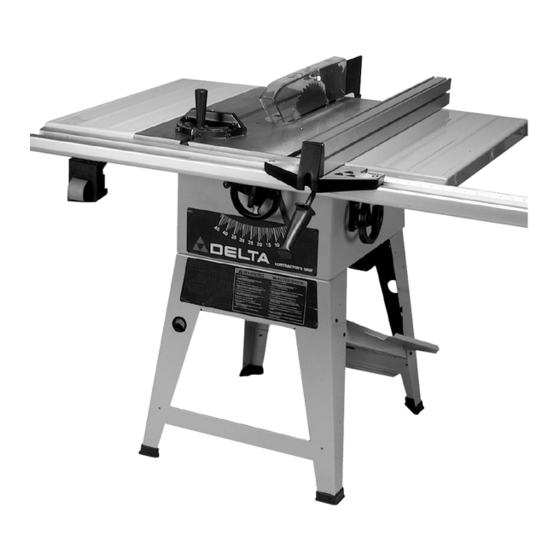
10" Contractor's Saw
(Models 36-441B, 36-451X)
NOTE: Shown with UniRip
®
Fence System
PART NO. 422-19-651-0058 - 03-22-04
Copyright © 2004 Delta Machinery
To learn more about DELTA MACHINERY
visit our website at: www.deltamachinery.com.
For Parts, Service, Warranty or other Assistance,
1-800-223-7278 (
1-800-463-3582).
please call
In Canada call
Advertisement
Table of Contents

Related Manuals for Delta 36-441B


Summary of Contents for Delta 36-441B
- Page 1 10" Contractor’s Saw (Models 36-441B, 36-451X) NOTE: Shown with UniRip ® Fence System PART NO. 422-19-651-0058 - 03-22-04 Copyright © 2004 Delta Machinery To learn more about DELTA MACHINERY visit our website at: www.deltamachinery.com. For Parts, Service, Warranty or other Assistance, 1-800-223-7278 ( 1-800-463-3582).
-
Page 2: Safety Guidelines - Definitions
SAFETY GUIDELINES - DEFINITIONS This manual contains information that is important for you to know and understand. This information relates to protect- ing YOUR SAFETY and PREVENTING EQUIPMENT PROBLEMS. To help you recognize this information, we use the symbols below. Please read the manual and pay attention to these sections. Indicates an imminently hazardous situation which, if not avoided, will result in death or serious injury. - Page 3 GENERAL SAFETY RULES FAILURE TO FOLLOW THESE RULES MAY RESULT IN SERIOUS PERSONAL INJURY. 1. FOR YOUR OWN SAFETY, READ THE INSTRUCTION 12. USE THE RIGHT MACHINE. Don’t force a machine or MANUAL BEFORE OPERATING THE MACHINE. Learning an attachment to do a job for which it was not the machine’s application, limitations, and specific designed.
- Page 4 ADDITIONAL SAFETY RULES FOR CONTRACTOR SAW FAILURE TO FOLLOW THESE RULES MAY RESULT IN SERIOUS PERSONAL INJURY. DO NOT OPERATE THIS MACHINE until it is 10. CUTTING THE WORKPIECE WITHOUT THE USE OF assembled installed according A FENCE OR MITER GAUGE IS KNOWN AS instructions.
-
Page 5: Power Connections
POWER CONNECTIONS A separate electrical circuit should be used for your machines. This circuit should not be less than #12 wire and should be protected with a 20 Amp time lag fuse. If an extension cord is used, use only 3-wire extension cords which have 3- prong grounding type plugs and matching receptacle which will accept the machine’s plug. -
Page 6: Extension Cords
3. Grounded, cord-connected tools intended for use on GROUNDED OUTLET BOX a supply circuit having a nominal rating between 150 - 250 volts, inclusive: CURRENT CARRYING PRONGS If the tool is intended for use on a circuit that has an outlet that looks like the one illustrated in Fig. -
Page 7: Functional Description
FUNCTIONAL DESCRIPTION FOREWORD Delta Model 36-441B 10" Contractor’s Saws are designed to give high quality performance with maximum depth of cut capacity up to 3-1/8" at 90° and 2-1/8" at 45°. These Delta Models come equipped with basic machine, sturdy steel stand, integral dust chute, patented Auto-Set T-Slot miter gage, heavy duty motor, large on/off paddle switch, extension wing, cast table, convenient up-front blade raising and tilting controls, and 10"... - Page 8 10. 1/4-20 x 3/4" Hex Head Bolts (2) 19*. 5/16-18 x 1" Flat head Screw (3) (36-451X only) -or- 3/8-16 x 1" Hex head Bolt (4) (36-441B only) 11. 1/4" Flat Washers (2) 20*. 5/16 Flat Washer (3) (36-451X only) -or- 12.
- Page 9 UNPACKING AND CLEANING Continued Fig. 3 " 12. 5/16 Hex Nuts (4) 1. Combination Dust Chute/Support Panel " 13. 5/16 Hex Nuts (8) 2. Motor Pulley " 14. 5/16 Lockwashers (8) 3. Motor " 15. 5/16 Flat Washers 4. Pulley Guard "...
-
Page 10: Saw Assembly
SAW ASSEMBLY DO NOT OPERATE THIS MACHINE UNTIL YOU READ AND UNDERSTAND THE ENTIRE INSTRUCTION MANUAL. MAKE SURE THE SAW IS SECURELY ATTACHED TO THE STAND BEFORE PERFORMING ANY CUTTING OPERATIONS. ASSEMBLING SAW STAND 1. Assemble the dust chute and support panel (A) Fig. -
Page 11: Assembling Blade Tilting Handwheel
4. Push down on the top of the saw (E) Fig. 8 until the stand legs (F) are positioned firmly on the floor surface. Securely tighten all saw and stand mounting hardware. Note that panel (G) is not only a support for a stand, but also serves as a dust chute. -
Page 12: Assembling Motor And Motor Mounting Plate To Saw
ASSEMBLING MOTOR AND MOTOR MOUNTING PLATE TO SAW DISCONNECT MACHINE FROM POWER SOURCE. 1. Locate the two pins (X) Fig. 12 that insert into holes (D) in each side of bracket (B). The pins (X) are spring (Y) loaded from factory. Fig. - Page 13 ASSEMBLING MOTOR PULLEY, BELT PULLEY GUARD, AND DRIVE BELT DISCONNECT MACHINE FROM THE POWER SOURCE. 1. Remove the motor shaft key that is taped to the motor. 2. Insert the key (A) Fig. 15 in the keyway on the motor shaft.
- Page 14 7. Lift the motor and assemble the drive belt (H) Fig. 19 to the arbor pulley and motor pulley (B). The weight of the motor will provide the correct belt tension. IMMEDIATELY AFTER ASSEMBLING THE BELT, RAISE THE SAW BLADE TO ITS MAXIMUM HEIGHT AND TILT THE SAW BLADE TO 45°.
- Page 15 ASSEMBLING AND ALIGNING BLADE GUARD AND SPLITTER ASSEMBLY ASSEMBLING BLADE GUARD AND SPLITTER ASSEMBLY DISCONNECT MACHINE FROM POWER SOURCE. 1. Fasten the rear splitter mounting bracket (A) Fig. 24, to the rear trunnion using the two 1/4-20 x 3/4" hex head bolts (B) and flat washers.
- Page 16 5. If alignment is necessary, loosen the two screws (F) Fig. 27, align bracket (D) with the arbor flange (E), and tighten screws (F). 6. Loosely assemble large washer and bolt (C) Fig. 27, to the inside splitter bracket. This bolt and washer was removed in STEP 3.
- Page 17 9. With the blade guard (L) Fig. 31, in the raised position, assemble the saw blade (K) on the saw arbor and tighten securely with two arbor wrenches supplied. See section “CHANGING SAW BLADE.” Fig. 31 10. Use a straight edge (E) to check to see if the saw blade is aligned with the rear of the splitter (G) in Figs.
- Page 18 EXTENSION AND SWITCH ASSEMBLY ASSEMBLING CAST IRON EXTENSION WING (MODEL 36-441B, 36-451X) DISCONNECT MACHINE FROM POWER SOURCE. 1. Assemble extension wing (A) Fig. 35, to the saw table using three 7/16-20 x 1-1/4" bolts (B) and lockwashers (C) Fig. 35.
-
Page 19: Fastening Stand To Supporting Surface
BACK SUPPORT RAIL MODEL 36-441B NOTE: IF YOUR MODEL DOES NOT USE A LEFT SIDE SHEET METAL WING, THE BACK RAIL SUPPORT IS NOT USED. Fasten the rear table support (A) Fig. 41, to the saw table. Insert a 3/8-16x1" hex head screw (B), through holes in rear support and table, place a 3/8 washer onto the screw and thread a 3/8-16 hex nut onto screw and tighten securely. -
Page 20: Operation And Adjustments
OPERATION AND ADJUSTMENTS RAISING AND LOWERING THE BLADE To raise the saw blade, loosen lock knob (A) Fig. 46, and turn the blade raising handwheel (B) clockwise. When the blade is at the desired height, tighten lock knob (A). To lower the blade, loosen lock knob (A) Fig. 46, and turn the handwheel (B) counterclockwise. - Page 21 CHECKING BLADE ALIGNMENT The saw has been aligned at the factory so the saw blade is parallel to the miter gage slots; however, it is recommended to check the alignment before initial operation as follows: DISCONNECT MACHINE FROM POWER SOURCE. 1.
-
Page 22: Backlash Adjustments For Blade Raising And Blade Tilting Mechanisms
BACKLASH ADJUSTMENTS BACKLASH ADJUSTMENTS FOR BLADE RAISING AND BLADE TILTING MECHANISMS After a period of extended use, if any play is detected in the blade raising or blade tilting mechanisms, make the following adjustments: DISCONNECT MACHINE FROM POWER SOURCE. 1. NOTE: The machine has been turned upside down and the blade removed for clarity and safety. -
Page 23: Adjusting Table Insert
ADJUSTING TABLE INSERT DISCONNECT MACHINE FROM POWER SOURCE. Place a straight edge across the table at both ends of the table insert. The table insert (A) Fig. 55 should always be level with the table. If an adjustment is necessary, turn the adjusting screws (B). - Page 24 COMMON SAWING OPERATIONS Common sawing operations include ripping and crosscutting plus a few other standard operations of a fundamental nature. As with all power machines, there is a certain amount of hazard involved with the operation and use of the machine.
- Page 25 RIPPING Ripping is cutting lengthwise through a board. The rip fence (A) Fig. 62 [not supplied] is used to position and guide the work. One edge of the work rides against the rip fence while the flat side of the board rests on the table. Since the work is pushed along the fence, it must have a straight edge and make solid contact with the table.
- Page 26 ACCESSORY MOULDING CUTTERHEAD USING MOULDING CUTTERHEAD Moulding is cutting a shape on the edge or face of the work. Cutting mouldings with a moulding cutterhead is a fast, safe and clean operation.The many different knife shapes available make it possible for the operator to produce almost any kind of mouldings, such as various styles of corner moulds, picture frames, table edges, etc.
- Page 27 SPECIAL ATTENTION SHOULD BE GIVEN THE GRAIN DIRECTION. MAKE ALL CUTS IN THE SAME DIRECTION AS THE GRAIN WHENEVER POSSIBLE. A LW AY S I N S TA L L B L A D E G U A R D AFTER OPERATION IS COMPLETE.
-
Page 28: Constructing A Featherboard
CONSTRUCTING A FEATHERBOARD Fig. 76, illustrates dimensions for making a typical featherboard. The material which the featherboard is constructed of, should be a straight piece of wood that is free of knots and cracks. Featherboards are used to keep the work in contact with the fence and table, as shown in Fig. -
Page 29: Constructing A Push Stick
CONSTRUCTING A PUSH STICK When ripping work less than 4 inches wide, a push stick should be used to complete the feed and could easily be made from scrap material by following the pattern shown in Fig. 78. -
Page 30: Dust Chute
STORAGE STORING THE MITER GAGE, AND ARBOR WRENCHES 1. When not in use, the miter gage (A) Fig. 79 can be stored through the hole located at the front side of the stand. 2. Arbor wrenches (C) Fig. 79, can be stored on one of the two notched legs. -
Page 31: Parts, Service Or Warranty Assistance
ACCESSORIES A complete line of accessories is available from your Delta Supplier, Porter-Cable • Delta Factory Service Centers, www.deltamachinery.com and Delta Authorized Service Stations. Please visit our Web Site for a catalog or for the name of your nearest supplier. Since accessories other than those offered by Delta have not been tested with this product, use of such accessories could be hazardous. - Page 32 • PORTER-CABLE DELTA SERVICE CENTERS • (CENTROS DE SERVICIO DE PORTER-CABLE DELTA) • Parts and Repair Service for Porter-Cable Delta Machinery are Available at These Locations • (Obtenga Refaccion de Partes o Servicio para su Herramienta en los Siguientes Centros de Porter-Cable Delta) Cleveland 44125 ARIZONA...