Table of Contents
Advertisement
Advertisement
Table of Contents

Related Manuals for Delta 36-655


Summary of Contents for Delta 36-655
- Page 1 10” Tilting Arbour Saw (Model 36-655) Part No. 1238007 Dated 11-01-03 Copyright © 2003 Delta Machinery To learn more about DELTA MACHINERY visit our website at: www.deltamachinery.com. For Parts, Service, Warranty or other Assistance, 1-800-223-7278 1-800-463-3582 please call (In Canada call...
-
Page 2: General Safety Rules
GENERAL SAFETY RULES... - Page 3 If you have any questions relative to a particular application, DO NOT use the machine until you have first contacted Delta to determine if it can or should be performed on the product.
-
Page 4: Additional Safety Rules For Table Saws
16. USE RECOMMENDED ACCESSORIES. The use of 21. NEVER LEAVE TOOL RUNNING UNATTENDED. accessories and attachments not recommended by Delta TURN POWER OFF. Don’t leave tool until it comes to a may cause hazards or risk of injury to persons. -
Page 5: Power Connections
Fig. 2. Contact your Check with a qualified electrician or service personnel if the local Authorized Delta Service Center or qualified grounding instructions are not completely understood, or if electrician for proper procedures to install the plug. The in doubt as to whether the machine is properly grounded. -
Page 6: Extension Cords
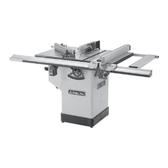
FOREWORD Delta Model 36-655 is a 10” Tilting Arbour Saw. The Model 36-655 has a powerful 1-3/4 HP induction motor which can handle tough cutting operations. The Model 36-655 comes with a heavy duty fence system with a 30” rip capacity to the right of the blade and a 24”... - Page 7 Fig. 5 Figure 5 The following saw parts require assembly. Please be sure all of the listed parts are included before starting assembly. 1. Right Extension Wing with Hex Screws (3), 10. Leveling Pads (4) Flat Washers (3), and Lock Washers (3) 11.
- Page 8 Fig. 6 Figure 6 1. Fence Assembly 4. Rear Rail with Square Head Screws (4), Flat Washers (4), Hex Nuts (4), End Caps (2), 2. Micro-adjust Assembly with Button Head and Self Tapping Screws (2) Screws (2) 5. Sliding Extension Table with Adjusting 3.
-
Page 9: Assembly Instructions
ASSEMBLY INSTRUCTIONS FOR YOUR OWN SAFETY, DO NOT PLUG SAW INTO OUTLET UNTIL THE TOOL IS COMPLETELY ASSEMBLED AND YOU READ AND UNDERSTAND THE ENTIRE INSTRUCTION MANUAL. Installing Leveling Pads Figure 7 With basic saw unit (A) turned base up, thread the (4) adjustable leveling pads (B) into the bottom of cabinet. -
Page 10: Installing Drive Belt
Installing Drive Belt Figure 11 Lift up on motor (A) and assemble drive belt ( B) to the arbor pulley (C) and the motor pulley (D). The weight of the motor will provide the correct tension. Fig. 11 Attaching Extension Wings to Saw Table Figure 12 This view shows the left extension wing (A) attached. - Page 11 Attaching Fence Rails and Sliding Extension Table Figure 15 Loosely attach square head screws (4), flat washers (4), and hex nuts (4) to the front edge of saw table and extension wings. Square heads are to be to the front. Fig.
- Page 12 Figure 19 Mount sliding extension table (A) into front and rear rail channels (B) using adjustment pads (C). Adjust pads for a smooth but snug fit. Fig. 19 Figure 20 Using a straight edge (A), check the level of the sliding table (B) with the right extension wing (C).
- Page 13 Figure 23 If alignment is necessary, loosen the two screws (A), align bracket (B) with the arbor flange and tighten screws (A). Loosely assemble large washer and hexhead screw (C) to the inside splitter bracket (B). Fig. 23 Figure 24 Install the blade guard and splitter assembly (A) between the large washer (B) and the splitter bracket.
-
Page 14: Installing Blade
Installing Blade DISCONNECT TOOL FROM POWER SOURCE. Figure 27 With the blade guard (A) in the raised position, assemble the saw blade (B) on the saw arbor using the two blade wrenches. Fig. 27 Figure 28 This view shows proper mounting of blade with teeth facing front of machine. -
Page 15: Installing Switch
Installing Switch DISCONNECT TOOL FROM POWER SOURCE. Figure 35 Mount switch (A) using hex head screws (2) and square nuts (2). Install screws with square nuts facing up (B). Do not tighten screws. Fig. 35 Figure 36 Slide square nuts (B) into bottom channel of front rail. Fig. -
Page 16: Dust Port
Tool Holders and Rail End Caps Figure 39 Install front and rear end caps (A) on both ends of fence rails using self tapping screws (4). Install fence holders (B) using self tapping pan head screws (4). Install wrench hook (C) using self tapping pan head screws (2). Install miter gage holder (D) using self tapping pan head screws (4). -
Page 17: Miter Gage
Miter Gage DISCONNECT TOOL FROM POWER SOURCE. Figure 43 The miter gage (A) is equipped with a T-slot bar (B). Engage bar at end of miter slot (C) and slide miter gage onto saw table. Fig. 43 Cross Cut Fence with Depth Stop DISCONNECT TOOL FROM POWER SOURCE. -
Page 18: Operating Controls And Adjustments
OPERATING CONTROLS AND ADJUSTMENTS Starting and Stopping the Saw Raising and Lowering Blade Blade Tilting Adjustment Figure 46 To apply power to the saw, depress the upper (green) button on switch (A). Pressing the lower (red) button turns the power OFF. DISCONNECT TOOL FROM POWER SOURCE. -
Page 19: Rip Fence Adjustments
Rip Fence Adjustments DISCONNECT TOOL FROM POWER SOURCE. Figure 49 Slide fence (A) against one edge of the miter gage slot (B). Lock the fence handle (C). The edge of the fence should be parallel with the edge of the miter gage slot. Fig. -
Page 20: Adjusting Table Insert
Setting Fence Micro-Adjust Figure Release locking handle (A). Push in micro-adjust knob (B) to engage mechanism, then turn handle right or left for precise settings. Release micro-adjust knob (B) and lock handle (A). Fig. 53 Figure 54 The miter gage is equipped with a T-slot bar (A) that allows it to extend past the front of table. -
Page 21: Maintenance
MAINTENANCE Changing the Saw Blade DISCONNECT TOOL FROM POWER SOURCE. Use only 10” Diameter Blades with 5/8” Arbor Holes, rated at 3450 RPM or Higher Figure 56 Remove table insert (A) and raise saw blade (B) to its maximum height. Fig. - Page 22 NOTES...
- Page 23 NOTES...
-
Page 24: Parts, Service Or Warranty Assistance
ACCESSORIES A complete line of accessories is available from your Delta Supplier, Porter-Cable • Delta Factory Service Centers, www.deltamachinery.com and Delta Authorized Service Stations. Please visit our Web Site for a catalog or for the name of your nearest supplier.