Table of Contents
Advertisement
Quick Links
Advertisement
Table of Contents

Related Manuals for Panasonic AW-HE870N


Summary of Contents for Panasonic AW-HE870N
-
Page 1: Operating Instructions
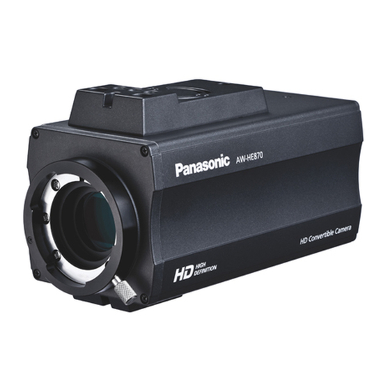
Operating Instructions HD Convertible Camera AW-HE870N Model No. Installation instructions provided AW-HE870 HIGH HD Convertible Camera DEFINITION Before operating this product, please read the instructions carefully and save this manual for future use. VQTB0350-1 F0109S1029... - Page 2 CAUTION RISK OF ELECTRIC SHOCK DO NOT OPEN CAUTION: TO REDUCE THE RISK OF ELECTRIC SHOCK, DO NOT REMOVE COVER (OR BACK). NO USER SERVICEABLE PARTS INSIDE. REFER TO SERVICING TO QUALIFIED SERVICE PERSONNEL. The lightning flash with arrowhead symbol, within an equilateral triangle, is intended to alert the user to the presence of uninsulated “dangerous voltage”...
- Page 3 WARNING: • TO REDUCE THE RISK OF FIRE OR ELECTRIC SHOCK, DO NOT EXPOSE THIS APPARATUS TO RAIN OR MOISTURE. • THE APPARATUS SHALL NOT BE EXPOSED TO DRIPPING OR SPLASHING AND THAT NO OBJECTS FILLED WITH LIQUIDS, SUCH AS VA S E S , S H A L L B E P L A C E D O N T H E APPARATUS.
-
Page 4: Important Safety Instructions
IMPORTANT SAFETY INSTRUCTIONS Read these operating instructions carefully before using the unit. Follow the safety instructions on the unit and the applicable safety instructions listed below. Keep these operating instructions handy for future reference. 1) Read these instructions. 2) Keep these instructions. 3) Heed all warnings. -
Page 5: Table Of Contents
Contents Preface ... 7 Standard accessories ... 7 Features ... 8 Special notes on operation ... 9 Precautions for use ... 10 Precautions for installation ... 12 Major operating controls and their functions ... 15 Front view / Top view / Rear view / Bottom view ... 15 Mounting ... - Page 6 Contents Menu item setting/changing ... 60 Menu item setting ... 60 Menu item setting/changing (Halogen, Fluorescent, Outdoor Mode) ... 62 Sub menu (Halogen, Fluorescent, Outdoor Mode) ... 62 Description of the setting screen ... 63 Menu item setting/changing (User Mode) ... 70 Sub menu (User Mode) ...
-
Page 7: Preface
Preface This is an HD/SD multi-format camera that adopts 14-bit analog to digital conversion and digital video signal processing, with a compact and lightweight 2/3˝ 3CCD system offering high reliability and availability of multiple functions. Setting and switching of the camera’s status and its various functions can be performed easily with the menu screen system. ... -
Page 8: Features
Features The camera features high reliability through adoption of 14-bit analog to digital conversion and digital video signal processing. Compatible with multiple formats • The format can be switched between 1080i, 720p, and 480i. The transition from an SD format system to an HD format system can be performed smoothly. -
Page 9: Special Notes On Operation
Special notes on operation Turn power off before connecting or disconnecting cables. Connection or disconnection of any studio cable or other cable to any unit of equipment must be performed while power is off. While the camera is in automatic mode; Shooting of bright objects in ELC operation mode may result in a smeared picture unique to the CCD. -
Page 10: Precautions For Use
Precautions for use DON’TS Do not attempt to disassemble the camera or other units. In order to prevent electric shock, do not remove screws or covers. There are no user-serviceable parts inside. Do not abuse the camera. Avoid striking, shaking, etc. The camera contains sensitive components which could be damaged by improper handling or storage. - Page 11 Precautions for use Refer any servicing to qualified service personnel. Handle the camera with care. Protect the precision made lens by placing the lens cap over when the camera is not in use. If the lens is not installed, protect the surface of the prism by placing the body cap into the lens mount hole.
-
Page 12: Precautions For Installation
Precautions for installation Concerning the installation location of the camera Ensure that the installation location is strong enough to bear at least five times the total weight of the camera, lens, and cables (approx. 55.1 lbs. [25 kg]). When mounting to a pan-tilt head or to a mounting bracket for installation, ensure that the location is strong enough to accommodate its weight as well. - Page 13 Attach the drop-prevention wire as a way to prevent the camera from dropping. When the unit is to be mounted onto a Panasonic pan-tilt head, use the mounting screws and drop-prevention wire that are supplied with the pan-tilt head.
- Page 14 Provide the following parts when the unit is to be mounted onto a surface other than a pan-tilt head. When the unit is to be mounted onto a Panasonic pan-tilt head, use the mounting screws and drop-prevention wire that are supplied with the pan-tilt head.
-
Page 15: Major Operating Controls And Their Functions
Major operating controls and their functions Front view / Top view / Rear view / Bottom view <Front view> <Rear view> <Top view> 11/16˝ (17.5 mm) 13/16˝ (20 mm) 1-1/4˝ 3/8˝ (10 mm) (32 mm) ... - Page 16 Major operating controls and their functions Lens mount 2/3˝ bayonet type lens or a microscope adapter can be mounted. Lens fixing ring knob Mount the lens on the camera and rotate the lens fixing ring knob clockwise in order to fix the lens securely. ...
- Page 17 Major operating controls and their functions UP/ABB switch [UP/ABB] The item just above can be selected by pressing this switch while the menu is displayed. When this switch is pressed while an item is able to be changed on a sub menu screen, the value is adjusted higher.
- Page 18 Major operating controls and their functions DC 12 V input connector [12 V The model AW-PS510A AC adapter (optional accessory) is connected here. For the connection, use a DC cable with ø5.5 plug which is supplied with AW-HE870. Cautions 1.
-
Page 19: Mounting
Mounting Lens mounting Use the 2/3˝ bayonet type lens (such as the AW-LZ17MD9AG and AK-LZ20M85G), available as an optional accessory. Note Use the AW-LZ17MD9AG lens when using the camera mounted on the pan-tilt head AW-PH360. Lenses other than the AW-LZ17MD9AG cannot be used. -
Page 20: Mounting The Camera Onto A Pan-Tilt Head, Tripod, Camera Mounting Bracket, Or Other Part
(M4). When the unit is to be mounted onto a Panasonic pan-tilt head, use the mounting screws and drop-prevention wire that are supplied with the pan-tilt head. - Page 21 Mounting Example where the camera is mounted on a ceiling or wall Hitch the end of the wire (Ceiling) onto the anchor bolt by tightening the nut or screw or by using a hook. Mounting screw (M4) Drop-prevention wire Mounting spacer (supplied) Flat washers...
- Page 22 Mounting Example of mounting the camera onto a bracket or tripod made by another manufacturer Mounting screw (M4) Hitch the end of the wire onto the anchor bolt by tightening the nut or screw or by using a hook. Drop-prevention wire Mounting spacer (supplied) Camera mounting screw holes...
- Page 23 Mounting 3. When mounting the camera onto a pan-tilt head (AW-PH400), do not use the anchoring rubber piece supplied with the pan-tilt head. If this rubber piece is used, the camera’s ventilation holes will be blocked, causing the temperature inside the camera to rise and possibly resulting in a malfunction.
-
Page 24: System Configuration (Connections)
System configuration (Connections) Connection of device with a composite/component input connector Connection to any device which has a composite signal input connector, such as a monitor or a VTR, must be made through the VIDEO OUT connector. Use the AW-CA50T8 camera control cable, which is available as an optional accessory, to connect the I/F REMOTE connector on the unit with the device equipped with HD/SD component signal input connectors. -
Page 25: Connection Of A Remote Operation Panel
System configuration (Connections) Connection of a remote operation panel When an SDI card (AW-HHD870) has been installed First, turn off the power of all the equipment before proceeding with the connections. Use the AW-PS510A for the AC adapter of the unit. Connect the DC 12 V OUT socket on the AW-PS510A to the DC 12 V IN socket on the unit using the DC cable provided with the AW-HE870. -
Page 26: Connection With Multiple Cameras (Supplying The External Synchronizing Signals)
System configuration (Connections) Connection with multiple cameras (Supplying the external synchronizing signals) Supply a synchronizing signal (BB) to the G/L input connectors of each camera. Do not switch off the camera used for supplying the external synchronizing signals. ... -
Page 27: Connection Of The Indoor Pan-Tilt Head Aw-Ph360
System configuration (Connections) Connection of the Indoor Pan-tilt Head AW-PH360 Turn off the power of all the equipment before proceeding with the connections. Connect the AC adapter (AW-PS300A) to the AW-PH360 indoor pan-tilt head. Use 10BASE-T straight cables to connect the RP connectors on the pan-tilt heads with the CONTROL OUT TO PAN/TILT HEAD (1 to 5) connectors on the AW-RP655 multi-function controller and AW-RP555 multi hybrid control panel. - Page 28 System configuration (Connections) Connection of the Indoor Pan-tilt Head AW-PH360 (continued) When an SDI card (AW-HHD870) has been installed Use a coaxial cable to connect the SDI OUT connector on the SDI card and the SDI IN connector on the AW-PH360. ...
- Page 29 System configuration (Connections) Connection of the Indoor Pan-tilt Head AW-PH360 (continued) When an SDI card (AW-HHD870) has been installed 10BASE-T straight cable Multi-Function Controller AW-RP655 AC Adapter AW-PS510A Remote Pan/Tilt Operation Control Panel Panel AW-CB400 AW-RP400 Pan-tilt head/camera control signals Multi Hybrid Control Panel AW-RP555...
-
Page 30: Connection Of The Indoor Pan-Tilt Head Aw-Ph400
System configuration (Connections) Connection of the Indoor Pan-tilt Head AW-PH400 Turn off the power of all the equipment before proceeding with the connections. Connect the AC power cable provided with the AW-PH400 to the AW-PH400 indoor pan-tilt head. ... - Page 31 System configuration (Connections) Connection of the Indoor Pan-tilt Head AW-PH400 (continued) When an SDI card (AW-HHD870) has been installed Use a coaxial cable to connect the SDI OUT connector on the SDI card and the SDI IN connector on the AW-PH400. ...
- Page 32 System configuration (Connections) Connection of the Indoor Pan-tilt Head AW-PH400 (continued) When an SDI card (AW-HHD870) has been installed Multi Hybrid Control Panel AC Adapter AW-RP555 AW-PS510A Multi-Function Controller AC Adapter AW-RP655 AW-PS510A Remote Pan/Tilt Control Operation Panel Panel AW-CB400 AW-RP400 To the LENS I/F (1)
-
Page 33: Connection Of The Indoor Pan-Tilt Head Aw-Ph405
System configuration (Connections) Connection of the Indoor Pan-tilt Head AW-PH405 Turn off the power of all the equipment before proceeding with the connections. Connect the AC power cable provided with the AW-PH405 to the AW-PH405 indoor pan-tilt head. ... - Page 34 System configuration (Connections) Connection of the Indoor Pan-tilt Head AW-PH405 (continued) When an SDI card (AW-HHD870) has been installed Use a coaxial cable to connect the SDI OUT connector on the SDI card and the SDI IN connector on the AW-PH405. ...
- Page 35 System configuration (Connections) Connection of the Indoor Pan-tilt Head AW-PH405 (continued) When an SDI card (AW-HHD870) has been installed 10BASE-T straight cable Multi-Function Controller AW-RP655 AC Adapter AW-PS510A Pan/Tilt Remote Control Operation Panel Panel AW-CB400 AW-RP400 AC Adapter AW-PS510A Pan-tilt head/camera control signals Multi Hybrid Control Panel...
-
Page 36: Connection Of The Outdoor Pan-Tilt Head Aw-Ph650
System configuration (Connections) Connection of the Outdoor Pan-tilt Head AW-PH650 Turn off the power of all the equipment before proceeding with the connections. Connect the AC adapter provided with the AW-PH650 to the AW-PH650 outdoor pan-tilt head. Use 10BASE-T straight cables to connect the RP connectors on the pan-tilt heads with the CONTROL OUT TO PAN/TILT HEAD (1 to 5) connectors on the AW-RP655 multi-function controller and AW-RP555 multi hybrid control panel. - Page 37 System configuration (Connections) Connection of the Outdoor Pan-tilt Head AW-PH650 (continued) When an SDI card (AW-HHD870) has been installed Use a coaxial cable to connect the SDI OUT connector on the SDI card and the SDI IN connector on the AW-PH650 main unit.
- Page 38 System configuration (Connections) Connection of the Outdoor Pan-tilt Head AW-PH650 (continued) When an SDI card (AW-HHD870) has been installed 10BASE-T straight cable Multi-Function Controller AW-RP655 AC Adapter AW-PS510A Pan/Tilt Remote Control Operation Panel Panel AW-RP400 AW-CB400 AC Adapter AW-PS510A Pan-tilt head/camera control signals Multi Hybrid Control Panel...
-
Page 39: How To Operate The System
How to operate the system Control exercised from the Remote Operation Panel AW-CB400 When using the AW-CB400, its switches and dials function as shown in the figure below. For capturing the camera statuses, and synchronizing the data. Flashes while data is being synchronized. *1 For selecting the cameras and pan-tilt head systems to be operated. - Page 40 How to operate the system Control exercised from the Remote Operation Panel AW-CB400 (continued) *1 : SCENE FILE, CAM/BAR, and DETAIL OFF/LOW/HIGH of each SCENE, as well as the GAINUP, AGC MAX GAIN, W/B MODE, R/B GAIN and T/R/B PED statuses are synchronized. Statuses are also acquired from the camera when the SCENE is switched or when the CAMERA MENU is turned OFF (including switching from MENU ENABLE to DISABLE).
- Page 41 How to operate the system Control exercised from the Remote Operation Panel AW-CB400 (continued) Procedure for camera menu operation (AW-CB400) Set the CAMERA MENU CNT item in the LCD menu of the AW-CB400 to ENABLE. Press the [A] button of the [OPTION SW] on the AW-CB400 for 2 seconds. ...
-
Page 42: Control Exercised From The Multi-Function Controller Aw-Rp655
How to operate the system Control exercised from the Multi-Function Controller AW-RP655 Each time the MODE button is pressed, the setting is switched between CAM and BAR. The MODE button lights up at the BAR setting. This is used to switch between AUTO and MANU for the gain. - Page 43 How to operate the system Control exercised from the Multi-Function Controller AW-RP655 (continued) *1 : When PRESET 3200K or PRESET 5600K is selected in the camera menu, everything turns off when the camera menu is turned OFF. *2 : The lamp of the ABB or AWB switch flashes while automatic white balance or automatic black balance is being executed, respectively.
- Page 44 How to operate the system Control exercised from the Multi-Function Controller AW-RP655 (continued) When the AW-HE870, to which the motor drive lens is connected, has been directly connected to the controller, zooming and focusing can be operated using the controller’s joystick. (When an SDI card is installed without using the pan-tilt head) Procedure for camera menu operation (AW-RP655) ...
- Page 45 How to operate the system Turn the jog dial (main) to select menu items of the AW-HE870 and change the data. When changing the data, the data settings are incremented by turning the dial clockwise and decremented by turning it counterclockwise.
-
Page 46: Control Exercised From The Multi Hybrid Control Panel Aw-Rp555
How to operate the system Control exercised from the Multi Hybrid Control Panel AW-RP555 Each time the GAIN button is pressed, the setting is switched in the sequence of GAIN AUTO 0dB L (9dB) H (18dB), and the mode is displayed by the LEDs as shown below. - Page 47 How to operate the system Control exercised from the Multi Hybrid Control Panel AW-RP555 (continued) *1 : The lamp of the ABB or AWB switch flashes while automatic white balance or automatic black balance is being executed, respectively. When ABB or AWB is completed successfully, the corresponding lamp goes off; when it is not completed successfully, it lights up.
- Page 48 How to operate the system Control exercised from the Multi Hybrid Control Panel AW-RP555 (continued) When the AW-HE870, to which the motor drive lens is connected, has been directly connected to the controller, zooming and focusing can be operated using the controller’s joystick. (When an SDI card is installed without using the pan-tilt head) Procedure for camera menu operation (AW-RP555) ...
-
Page 49: Use Mode Setting
Use mode setting Use Mode Setting The camera has four use modes, and various functions for four use modes have been preset. Functions can be set as best suited to each use mode. Halogen mode Suited to indoor shooting, such as at weddings, parties, lecture meetings, events, etc. Settings can be changed using a simple menu. -
Page 50: Selecting
Use mode setting Selecting 1. Turn the camera on while keeping the MENU switch depressed. The use mode setting menu appears on the monitor screen. 2. The cursor moves each time the UP/ABB switch or the DOWN/BAR switch is pressed. Move the cursor to the desired use mode. -
Page 51: Operating Procedure
Operating procedure Turn on the power of the camera and other units. Adjust the lighting of the subject to the appropriate level. Select the operating mode. Once the mode has been selected, it need not be selected again when the camera is going to be used under the same conditions. -
Page 52: Adjustment
Adjustment Flange back adjustment (For zoom lens) This is for adjusting the zoom lens focus over the entire focusing range from the TELE end to the WIDE end. 1. Fully open the iris by shooting a dark object. 2. Aim the camera at any object over 6.56 ft. (2 m) away from the camera, and then loosen the flange back lock knob. -
Page 53: White Balance Adjustment
Adjustment White balance adjustment Automatic white balance control (AWB: AWB A/AWB B) When “AWB A” or “AWB B” has been selected as the white balance setting on the Color Set sub menu (pages 62, 70), two sets of color temperature conditions can be preset (stored in the memory): one set for A and another set for B. - Page 54 Adjustment Notes White balance may not be correctly set if the lighting of the object is too weak. Since the camera has a built-in memory, the set white balance will remain in the memory even if power is turned off. Therefore, it is not necessary to reset the white balance if the color temperature of those objects remains unchanged.
-
Page 55: Black Balance Adjustment
Adjustment Black balance adjustment Close the lens. If the motor drive lens is controlled from the camera, the lens is automatically closed when the black balance is adjusted. The R/B pedestal adjustment of painting setting will be automatically reset to ±0 after setting the black balance. -
Page 56: Total Pedestal Level Adjustment
Adjustment Total pedestal level adjustment (Use an oscilloscope or a waveform monitor for this adjustment.) This step is to adjust the black levels (pedestal levels) of two or more cameras to be the same. Please contact your dealer for the adjustment. 1. -
Page 57: Genlock Adjustment
Adjustment Genlock adjustment Phase adjustments must be performed with the camera menu when external synchronizing signals are supplied to the system in cases where multiple cameras are used or peripheral devices are connected. Please contact your dealer for the adjustment. Notes ... - Page 58 Adjustment • When adjusting the phase of SD signals Observe the waveforms of the external synchronizing input signal (black burst signal) and video output signal on a two-channel oscilloscope. Then match the horizontal phase of both signals by adjusting them with the horizontal phase control of the camera menu.
- Page 59 Adjustment Color phase adjustment Color phase adjustment is necessary only for the composite or Y/C signals of the SD format. Adjust the color phase of the camera to the basic color tone such as program output signal (split color bar output signal) from the color special effect generator.
-
Page 60: Menu Item Setting/Changing
Menu item setting/changing Menu item setting Each of the four use modes of the camera (Halogen, Fluorescent, Outdoor and User) has a main menu. (Refer to page 61.) Each item of the main menu has a sub menu, which consists of several settings. - Page 61 Menu item setting/changing 6. Upon completion of the settings, keep the MENU switch depressed for 3 seconds or more to close the main menu screen. The camera will now operate according to the new settings. MENU switch ENTER/AWB switch UP/ABB switch DOWN/BAR switch ...
-
Page 62: Menu Item Setting/Changing (Halogen, Fluorescent, Outdoor Mode)
Menu item setting/changing (Halogen, Fluorescent, Outdoor Mode) Sub menu (Halogen, Fluorescent, Outdoor Mode) Brightness Set Display Brightness Set Picture Level ––––––– Light PEAK/AVG ––––––– Light Area Top Cut ––––––– Shutter Mode Step ––––––– Step/Synchro –––––––––... -
Page 63: Description Of The Setting Screen
Menu item setting/changing (Halogen, Fluorescent, Outdoor Mode) Description of the setting screen Brightness Set Video level adjustment [Picture Level: –50 to +50] Convergence level of AUTO IRIS, AUTO GAIN UP and AUTO ND (ELC) can be adjusted. Detecting ratio adjustment [Light PEAK/AVG: P50 to A50] The ratio of AUTO IRIS, AUTO GAIN UP and AUTO ND (ELC) detected peak (P) to average (A) can be adjusted... - Page 64 Menu item setting/changing (Halogen, Fluorescent, Outdoor Mode) Electronic shutter step/synchro scan setting [Step/Synchro: Off, 1/100 to 1/10000 (Step), 61.19 Hz to 1466 Hz (Synchro Scan)] This setting is possible only when “Step” or “S/Scan” is selected in electronic shutter mode setting. •...
- Page 65 Menu item setting/changing (Halogen, Fluorescent, Outdoor Mode) Color Set Chroma level adjustment [Chroma Level: –3 to +3] Chroma level can be decreased or increased to any of three levels each. The RGB signal cannot be adjusted. Skin color adjustment [Flesh Tone: –3 to +3] Skin color can be decreased or increased to any of three levels each.
- Page 66 Menu item setting/changing (Halogen, Fluorescent, Outdoor Mode) Sharpness (DTL) Set Detail select setting [DTL Select: Sharpness, Super DTL] If contour correction is not sufficient at the “Sharpness” position when detail level setting is set to “Low” or “High”, select the “Super DTL”...
- Page 67 Menu item setting/changing (Halogen, Fluorescent, Outdoor Mode) G/L Set Horizontal phase adjustment [H Phase: –206 to +49] Horizontal phase can be adjusted when a genlock signal is supplied. Subcarrier phase coarse adjustment [SC Coarse: 0deg, 45deg, 90deg, 135deg, 180deg, 225deg, 270deg, 315deg] Coarse adjustment of subcarrier phase can be made when a genlock signal is supplied.
- Page 68 Menu item setting/changing (Halogen, Fluorescent, Outdoor Mode) Down-conversion mode selection [Downconv. Mode: Squeeze, Sidecut] Squeeze or Sidecut can be selected as the down-conversion mode for the SD (480i) format. Component output setting [Component: RGB, Y/Pb/Pr, Y/C] This enables RGB, Y/Pb/Pr or Y/C to be selected as the component signals which are to be output from the I/F REMOTE connector.
- Page 69 Menu item setting/changing (Halogen, Fluorescent, Outdoor Mode) Character output selection [ Character Mix Component: Off, On / Composite: Off, On / Option: Off, On] This is used to select how the camera menu, status and other characters are to be output (Off or On). Component: How the characters to the component signals (RGB, Y/Pb/Pr) are output is selected.
-
Page 70: Menu Item Setting/Changing (User Mode)
Menu item setting/changing (User Mode) Sub menu (User Mode) Brightness Set Display Brightness Set ––––––– Picture Level ––––––– Light PEAK/AVG ––––––– Light Area Top Cut ––––––– Shutter Mode Step Step/Synchro ––––––––– Gain ––––––– ... - Page 71 Menu item setting/changing (User Mode) SD Detail Set Display SD Detail Set 1/2 ––––––– Detail High ––––––––– H Detail Level H ––––––––– V Detail Level H H Detail Level L ––––––––– V Detail Level L –––––––––...
- Page 72 Menu item setting/changing (User Mode) G/L Set Display G/L Set ––––––– H Phase ––––––– SC Coarse 90deg ––––––– SC Fine H Phase,SC Fine Step ––––––– Return Other Set Display Other Set 1 ––––––– Gamma 0.45 ...
-
Page 73: Description Of The Setting Screen
Menu item setting/changing (User Mode) Description of the setting screen Brightness Set Video level adjustment [Picture Level: –50 to +50] Convergence level of AUTO IRIS, AUTO GAIN UP and ELC can be adjusted. Detecting ratio adjustment [Light PEAK/AVG: P50 to A50] The ratio of AUTO IRIS, AUTO GAIN UP and ELC detected peak (P) to average (A) can be adjusted within a predetermined range. - Page 74 Menu item setting/changing (User Mode) Electronic shutter step/synchro scan setting [Step/Synchro: Off, 1/100 to 1/10000 (Step), 61.19 Hz to 1466 Hz (Synchro Scan)] This setting is possible only when “Step” or “S/Scan” is selected in electronic shutter mode setting. •...
- Page 75 Menu item setting/changing (User Mode) Color Set Chroma level adjustment [Chroma Level: –3 to +3] Chroma Level can be decreased or increased to any of three levels each. The RGB signal cannot be adjusted. White balance setting [White Bal: ATW, AWB A, AWB B, 3200K, 5600K] ATW: The white balance is automatically adjusted to...
- Page 76 Menu item setting/changing (User Mode) HD (1080i, 720p) Detail Set Detail level setting [Detail: Off, Low, High] Contour correction quantity can be selected. Detail settings made using the horizontal/vertical detail level high/low setting. Horizontal detail level high setting [H Detail Level H: L+1 to +63] ...
- Page 77 Menu item setting/changing (User Mode) Dark detail level setting [Dark Detail: 0 to 5] The contours of the darker portions of an object can be emphasized. This setting is possible only when the level dependent level setting is set to “0 %”. ...
- Page 78 Menu item setting/changing (User Mode) SD (480i) Detail Set Detail level setting [Detail: Off, Low, High] Contour correction quantity can be selected. Detail settings made using the horizontal/vertical detail level high/low setting. Horizontal detail level high setting [H Detail Level H: L+1 to +63] ...
- Page 79 Menu item setting/changing (User Mode) Dark detail level setting [Dark Detail: 0 to 5] The contours of the darker portions of an object can be emphasized. This setting is possible only when the level dependent level setting is set to “0 %”. ...
- Page 80 Menu item setting/changing (User Mode) Color Matrix Set Linear Matrix R-G [Matrix(R-G): –31 to +31] This is used to adjust the color in the R-G axis direction. Linear Matrix R-B [Matrix(R-B): –31 to +31] This is used to adjust the color in the R-B axis direction. Linear Matrix G-R [Matrix(G-R): –31 to +31] This is used to adjust the color in the G-R axis direction.
- Page 81 Menu item setting/changing (User Mode) Color Correction Set B_Mg Gain [–127 to +127] Increases or decreases the intermediate color between blue and magenta. B_Mg Phase [–127 to +127] Varies the hue of the intermediate color between blue and magenta. Mg Gain [–127 to +127] Increases or decreases the magenta.
- Page 82 Menu item setting/changing (User Mode) G/L Set Horizontal phase adjustment [H Phase: –206 to +49] Horizontal phase can be adjusted when a genlock signal is supplied. Subcarrier phase coarse adjustment [SC Coarse: 0deg, 45deg, 90deg, 135deg, 180deg, 225deg, 270deg, 315deg] Coarse adjustment of subcarrier phase can be made when a genlock signal is supplied.
- Page 83 Menu item setting/changing (User Mode) Flare correction level setting [Flare R/G/B: 0 to 100] Flare correction level can be adjusted. Black stretch setting [Black Stretch: Off, On] Black stretch to correct the suppression of black portions at low luminance can be set to OFF or ON. ...
- Page 84 Menu item setting/changing (User Mode) Component output setting [Component: RGB, Y/Pb/Pr, Y/C] This enables RGB, Y/Pb/Pr or Y/C to be selected as the component signals which are to be output from the I/F REMOTE connector. Y/C cannot be selected when “1080i” or “720p” has been selected as the “Video output format (Format)”...
- Page 85 Menu item setting/changing (User Mode) Character output selection [ Character Mix Component: Off, On / Composite: Off, On / Option: Off, On] This is used to select how the camera menu, status and other characters are to be output (Off or On). Component: How the characters to the component signals (RGB, Y/Pb/Pr) are output is selected.
-
Page 86: Changing The Settings
Changing the settings Changing the format settings A confirmation screen appears when the format setting is to be changed on the Other Set screen. 1. When the Format setting is changed on the Other Set screen and the ENTER/AWB switch is pressed, the “Format”... -
Page 87: Changing The Component Setting
Changing the settings Changing the component setting A confirmation screen appears when the component setting is to be changed on the Other Set screen. 1. When the Component setting is changed on the Other Set screen and the ENTER/AWB switch is pressed, the “Component”... -
Page 88: Setting The Ebu Matrix
Changing the settings Setting the EBU matrix A confirmation screen appears when the EBU matrix is to be set on the Other Set screen. 1. When the EBU matrix setting is changed on the Other Set screen and the ENTER/AWB switch is pressed, the “EBU Matrix”... -
Page 89: Setting To Initial Set (Factory Presets)
Setting to initial set (Factory presets) Setting to initial set In case of the wrong setting in any use mode, take the following steps to return to the initial settings. When initialization is performed, all of the camera menu’s setting values except for Format and Component will return to factory presets. -
Page 90: Initial Settings Of The Setting Items
Setting to initial set (Factory presets) Initial settings of the setting items (Factory preset values) Halogen, Fluorescent, Outdoor Mode Item Brightness Set Picture Level Light PEAK/AVG Light Area Shutter Mode Step/Synchro Gain AGC Max Gain Pedestal Color Set Chroma Level Flesh Tone White Bal ATW Speed... -
Page 91: User Mode
Setting to initial set (Factory presets) User Mode Item Brightness Set Picture Level Light PEAK/AVG Light Area Shutter Mode Step/Synchro Gain AGC Max Gain Pedestal Color Set Chroma Level White Bal ATW Speed Painting R Gain B Gain R Pedestal B Pedestal HD Detail Set 1/2 Detail... - Page 92 Setting to initial set (Factory presets) Item Color Correction 2/3 R_YI Gain R_YI Phase YI Gain YI Phase YI_G Gain YI_G Phase G Gain G Phase Color Correction 3/3 G_Cy Gain G_Cy Phase Cy Gain Cy Phase Cy_B Gain Cy_B Phase B Gain B Phase G/L Set*...
-
Page 93: Troubleshooting
Troubleshooting Operation Symptom When the pan-tilt head is not being used Are the DC cable provided with the unit and the designated AC adapter connected? Has the POWER switch of the AC adapter been set to the ON position? No power ... - Page 94 Troubleshooting Symptom It may be necessary to upgrade the version of the controller so that the controller will support the unit. Consult with your dealer. Cannot operate When the AW-RP400 pan-tilt control panel and the AW-CB400 remote using the controller operation panel are used in combination, a setting that prohibits the operation of one of these units may have been selected.
- Page 95 Troubleshooting Video Symptom Is the unit connected to the pan-tilt head and controller properly? Refer to the Operating Instructions of the pan-tilt head or the controller. Has the power of the connected equipment been turned on? ...
- Page 96 Troubleshooting Symptom Have the white balance and black balance been adjusted? Adjust the white balance and black balance. The automatic tracking white balance setting (ATW) function may also be selected. Something is wrong Have the color matrix settings or color correction settings been changed? with the coloring of ...
- Page 97 Troubleshooting Symptom Multiple color bands Switch to the camera picture. (color bars) are displayed The controller’s Restart the unit, and check that “Fan Error” is displayed. H/F and OPTION The cooling fan inside the unit has reached the end of its service life or it has indicators flash failed.
-
Page 98: Appearance
Appearance Unit: inch (mm) AW-HE870 HIGH HD Convertible Camera DEFINITION 6-3/4 (171) 3-1/4 (83) (12) - 98 -... -
Page 99: Specifications
Specifications Source voltage: DC 12 V Power consumption: 18.5 W Optical system: Dichroic prism optical system, F1.4 Pickup device: 2/3˝ Interline wide CCD Internal synchronization, External synchronization: BB (BNC 1, Dsub 50P 1) Synchronization system: Video output: <HD format> Y/Pb/Pr <SD format>... - Page 100 Specifications White balance: AWB A, AWB B (R/B painting), ATW, 3200K/5600K preset Black balance: Auto (R/B painting) Chroma amount variability: 7 levels variability Encoding system: Y, R-Y, B-Y Gain selection: –6 to 18 dB in step, AGC Electronic shutter speed: 1/100, 1/250, 1/500, 1/1000, 1/2000, 1/4000, 1/10000, ELC, Synchro scan (61.19 Hz to 1466 Hz) Color bars:...
- Page 101 Specifications Allowable temperature ranges: For storage: For guaranteeing performance: 41 °F to 95 °F (+5 °C to +35 °C) For guaranteeing operation: Ambient operating humidity: For storage: For guaranteeing operation: Dimensions (W H D): 3-1/4˝ 4-1/8˝ 7-9/16˝ (83 104.5 192 mm) [excluding protrusions] Weight: Approx.
- Page 102 Memo...
- Page 103 Memo...
- Page 104 PANASONIC BROADCAST & TELEVISION SYSTEMS COMPANY UNIT COMPANY OF PANASONIC CORPORATION OF NORTH AMERICA Headquarters: 3 Panasonic Way 4E-7, Secaucus, NJ 07094 (201) 348-5300 EASTERN ZONE: 3 Panasonic Way 4E-7, Secaucus, NJ 07094 (201) 348-7196 WESTERN ZONE: 3330 Cahuenga Blvd. West, Los Angeles, CA 90068 (323) 438-3608...