Toro Workman HD 07369 Operator's Manual
Hide thumbs
Also See for Workman HD 07369:
- Operator's manual (52 pages) ,
- Operator's manual (56 pages)

Related Manuals for Toro Workman HD 07369


Summary of Contents for Toro Workman HD 07369
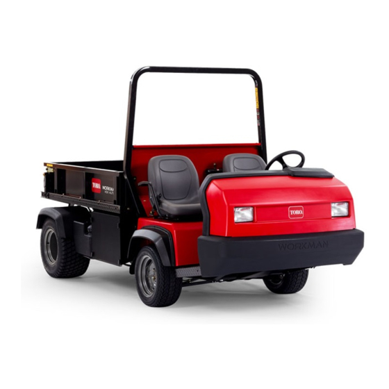
- Page 1 Form No. 3362-635 Rev B Workman ® HD Utility Vehicle Model No. 07369—Serial No. 290000001 and Up To register your product or download an Operator's Manual or Parts Catalog at no charge, go to www.Toro.com. Original Instructions (EN)
-
Page 2: Introduction
Whenever you need service, genuine Toro parts, or additional information, contact an Authorized Service Dealer or Toro Customer Service and have the model and serial numbers of your product ready. Figure 1 identifies the location of the model and serial numbers on the product. -
Page 3: Table Of Contents
Contents Using the Bed Safety Support......32 Removing the Full Bed ........33 Installing the Full Bed......... 33 Introduction..............2 Jacking the Vehicle..........34 Safety ................4 Removing the Hood ........... 35 Safe Operating Practices ........4 Lubrication............. 36 Supervisor’s Responsibilities ......... 4 Greasing Bearings and Bushings ...... -
Page 4: Safety
Safety Not all of the attachments that adapt to the Workman are covered in this manual. See the specific Operator’s Manual provided with each attachment for additional The machine meets the requirements of SAE J2258. safety instructions. Read these manuals. Supervisors, operators and service persons should be To reduce the potential for injury or death, comply familiar with the following standards and publications:... -
Page 5: While Operating
is corrected before vehicle or attachment is operated – If engine is cold—press and hold the accelerator again. pedal about half way down and pull the choke knob out to the On position while cranking the • Since gasoline is highly flammable, handle it carefully. engine. -
Page 6: Maintenance
• Before getting off the seat, do the following: • To be sure of optimum performance and safety, – Stop movement of the machine. always purchase genuine Toro replacement parts and – Lower the bed. accessories. Replacement parts and accessories made –... -
Page 7: Vibration Level
Vibration Level Hand-Arm This unit does not exceed a vibration level of 2.5 m/s the hands based on measurements of identical machines per ISO 5349 procedures. Whole Body This unit does not exceed a vibration level of 0.5 m/s at the posterior, based on measurements of identical machines per ISO 2631 procedures. -
Page 8: Safety And Instructional Decals
Safety and Instructional Decals Safety decals and instructions are easily visible to the operator and are located near any area of potential danger. Replace any decal that is damaged or lost. 93-9852 1. Warning—read the Operator’s Manual. 2. Crushing hazard—install the cylinder lock. 115-2047 1. - Page 9 106-2353 1. Electrical power point 106-2355 1. Slow 3. Transmission—third high; no fast speed 2. Fast 106-7767 93–9868 1. Warning—read the Operator’s Manual; avoid tipping the 1. Crushing hazard of hand—read the Operator’s Manual. machine; wear the seat belt; lean away from the direction the machine is tipping.
- Page 10 115-2282 1. Warning—read the Operator’s Manual. 2. Warning—stay away from moving parts, keep all guards and shields in place. 3. Crushing/dismemberment hazard of bystanders—keep bystanders a safe distance from the vehicle, do not carry passengers in the cargo bed, keep arms and legs inside of the vehicle at all times, and use seat belts and handholds. 115-2281 1.
- Page 11 115-7814 115-7746 1. Warning—do not operate this machine unless you are trained. 3. Fire hazard—stop the engine before fueling. 2. Warning—lock the parking brake, stop the engine, and 4. Tipping hazard—slow down and turn gradually, use caution remove the ignition key before leaving the machine. and drive slowly when driving on slopes, do not exceed 20 mph (32 kph), and drive slowly over rough terrain or when carrying a full or heavy load.
- Page 12 106-2377 1. Locked 8. Warning—read the Operator’s Manual. 2. Differential lock 9. Entanglement hazard, shaft—keep bystander’s a safe distance from the vehicle. 3. Unlocked 10. Retract hydraulics 4. Hydraulic lock 11. Extend hydraulics 5. Engage 12. Transmission—high speed 6. Power take-off (PTO) 13.
-
Page 13: Setup
Setup Loose Parts Use the chart below to verify that all parts have been shipped. Procedure Description Qty. Check the engine oil, transaxle/hydraulic – No parts required fluid, and brake fluid levels Media and Additional Parts Description Qty. Operator’s Manual (Vehicle) Read before operating machine Parts Catalog Use to reference part numbers... -
Page 14: Product Overview
Product Overview Worn or maladjusted brakes may result in Controls personal injury. If the brake pedal travels to within 1-1/2 inches (3.8 cm) of the vehicle floor Note: Determine the left and right sides of the machine board, the brakes must be adjusted or repaired. from the normal operating position. -
Page 15: Parking Brake
• Shift only on level ground. • Press clutch pedal fully. • Move the lever fully forward for High and fully rearward for Low. High is for higher speed driving on level, dry surfaces with light loads. Low is for low speed driving. Use this range when greater than normal power or control is required. -
Page 16: Light Switch
If the oil level was low, but adding oil does not cause the light to go out when the engine is restarted, turn the engine off immediately and contact your local Toro distributor for assistance. Check the operation of warning lights as follows: 1. Apply the parking brake. -
Page 17: Specifications
30, etc.) are not recommended in Kohler engines due Authorized Service Dealer or Distributor or go to to problems with pump-up of hydraulic lifters with www.Toro.com for a list of all approved attachments those oils. Either synthetic or mineral based oils may and accessories. -
Page 18: Adding Fuel
Adding Fuel 4. Remove the dipstick and check the oil level. The Toro® Company strongly recommends the 5. If the oil level is low, remove the filler cap (Figure 9) use of fresh, clean, unleaded regular grade gasoline and add enough oil to raise the level to the Full in Toro gasoline powered products. - Page 19 In certain conditions, gasoline is extremely In certain conditions during fueling, static flammable and highly explosive. A fire or electricity can be released causing a spark explosion from gasoline can burn you and which can ignite the gasoline vapors. A fire others and can damage property.
-
Page 20: Checking The Transaxle/Hydraulic Fluid Level
Checking the Torque of the 3. Fill the tank to about one inch below the top of the tank, (bottom of the filler neck), then install the cap. Wheel Nuts Do not overfill. Service Interval: After the first 2 hours 4. -
Page 21: Checking The Brake Fluid
3. If the fluid level is low, clean the area around the • Check all fluid levels and add the appropriate cap, remove the reservoir cap, and fill the reservoir amount of Toro specified fluids, if any are found to the proper level. Do not overfill. to be low. -
Page 22: Starting The Engine
• Turn the steering wheel to the left and right to 4. Release the clutch pedal smoothly while pressing check the steering response. the accelerator pedal. 5. When the vehicle gains enough speed, remove your • Stop the engine and wit for moving parts to stop, foot from the accelerator pedal, fully press the then check for oil leaks, loose parts, and any other clutch pedal, move the gear shift lever to the next... -
Page 23: Checking The Interlock System
• Check the fluid and engine oil levels regularly If the engine cranks or starts, there is a malfunction and be alert for indications of overheating in any in the interlock system that must be repaired before component of the vehicle. operating the vehicle. -
Page 24: Passengers
on different surfaces. Your operating skills will improve with experience, but as in operating any vehicle, take it easy as you begin. Be sure you know how to stop quickly in an emergency. If you need help, ask your supervisor for assistance. Many factors contribute to accidents. -
Page 25: Turning
Tip Overs When using heavy attachments, more than 1000 lb (454 kg), such as sprayers, top dressers, or spreaders, etc., The vehicle is equipped with a roll bar, hip restraints, restrict your operating speed by moving the 3rd high seat belts, and hand hold. The ROPS system (Rollover lockout switch to the slow position. -
Page 26: Loading And Dumping
the level. Turns while going down hill, especially with capacity and versatility. The full sized box is 55 inches the brakes on, and, turning up hill while traversing a (140 cm) wide by 65 inches (165 cm) long and can hold hill are particularly dangerous. -
Page 27: Transporting Vehicle
In case of an emergency, the vehicle can be towed for Important: Trailers weighing over 1500 lb (680 kg) a short distance. However, Toro does not recommend are required to be equipped with trailer brakes. this as a standard procedure. -
Page 28: Towing A Trailer With The Vehicle
Several types of tow hitches are available for the off position. Workman, depending on your application. Contact your Authorized Toro Distributor for details. When equipped with a tow hitch bolted onto the rear axle tube, your Workman can tow trailers or attachments with a Gross Trailer Weight (GTW) up to 3500 lb (1587 kg). - Page 29 Troubleshooting the Hydraulic Control the hydraulic system. Use this position only momentarily or with a motor attached. • Difficulty in connecting or disconnecting quick couplers. Important: Check hydraulic oil level after installation of an attachment. Check the Pressure not relieved (Quick coupler under operation of the attachment by cycling the pressure).
-
Page 30: Maintenance
Maintenance Determine the left and right sides of the machine from the normal operating position. Only qualified and authorized personnel shall be permitted to maintain, repair, adjust, or inspect the vehicle. Avoid fire hazards and have fire protection equipment present in the work area. Do not use an open flame to check level or leakage of fuel, battery electrolyte, or coolant. -
Page 31: Service Interval Chart
Maintenance Service Maintenance Procedure Interval • Torque the front and rear wheel nuts • Change the air cleaner paper element. • Check the adjustment of the shift cables. • Check the adjustment of the high–low cable. • Check the adjustment of the differential lock cable. •... -
Page 32: Heavy Duty Operation
Heavy Duty Operation Important: If the vehicle is subjected to any of the conditions listed below, maintenance should be performed twice as frequently: • Desert operation • Cold climate operation below 32 degrees F (0 degrees C) • Trailer towing •... -
Page 33: Removing The Full Bed
Installing the Full Bed Note: If the bed sides will be installed on the flat bed, Do not try to lower bed with bed safety support it is easier to install them before installing the bed on on cylinder. the vehicle. Note: Ensure that the rear pivot plates are bolted to Removing the Full Bed the bed frame/channel so that lower end angles to the... -
Page 34: Jacking The Vehicle
Jacking the Vehicle A vehicle on a jack may be unstable and slip off of the jack, injuring anyone beneath it. • Do not start the vehicle while the vehicle is on a jack. • Always remove the key from the switch before getting off of the vehicle. -
Page 35: Removing The Hood
To install the hood, complete the following: 1. Connect the lights. 2. Insert the top mounting tabs into the frame slots. 3. Insert the lower mounting tabs into the frame slots. 4. Ensure that the hood is fully engaged in the top, sides and bottom grooves. -
Page 36: Lubrication
Lubrication Greasing Bearings and Bushings Service Interval: Every 100 hours (Lubricate more frequently in heavy duty applications) The vehicle has grease fittings that must be lubricated regularly with No. 2 General Purpose Lithium Base Grease. The grease fitting locations and quantities are as follows: •... -
Page 37: Engine Maintenance
Engine Maintenance Note: With the air cleaner disassembled, check the air cleaner components for damage. Replace and damaged parts. Servicing the Air Cleaner 4. Install the element with the pre-cleaner, breather seal, inner cover, wing nut, air cleaner cover, O-ring, Service Interval: Every 50 hours—Clean and oil the and knob. -
Page 38: Replacing The Spark Plugs
Replacing the Spark Plugs Fuel System Maintenance Service Interval: Every 800 hours The spark plugs usually last a long time; however, the plugs should be removed and checked whenever the Replacing the Fuel Filter engine malfunctions or every 800 hours. Replace the spark plugs to ensure proper engine performance and Service Interval: Every 400 hours reduce exhaust emission level. -
Page 39: Electrical System Maintenance
Jump Starting the Vehicle Electrical System Maintenance Jump starting can be dangerous. To avoid Fuses personal injury or damage to electrical components in vehicle, observe the following The fuses for the machine’s electrical system are warnings: located under the center of the dash panel (Figure 39 &... -
Page 40: Servicing The Battery
cable to the negative post of the discharged battery. Connect it to the engine or frame. Do not connect the jumper cable to the fuel system. Battery electrolyte contains sulfuric acid which is a deadly poison and causes severe burns. •... -
Page 41: Drive System Maintenance
Adjusting Differential Lock Drive System Cable Maintenance Service Interval: Every 200 hours Adjusting the Shift Cables 1. Move the differential lock lever to the Off position. 2. Loosen the jam nuts securing the differential lock Service Interval: After the first 10 hours cable to the bracket on the transaxle (Figure 44). -
Page 42: Checking The Front Wheel Alignment
Figure 45 Figure 47 1. Under inflated tire 1. Front of vehicle 3. Center to center distance 2. 0 ± 0.12 inch (0 ± 3 mm) front to rear of tire Figure 46 is an example of tire wear caused by over inflation. -
Page 43: Cooling System Maintenance
Brake Maintenance Cooling System Maintenance Adjusting the Parking Brake Removing Debris from the Service Interval: After the first 10 hours Engine Cooling System Every 200 hours 1. Remove the rubber grip from the parking brake lever Service Interval: Every 100 hours (Clean more (Figure 49). -
Page 44: Adjusting The Brake Pedal
Adjusting the Brake Pedal Belt Maintenance Service Interval: Every 200 hours Adjusting the Pump Drive Belt Note: Remove the font hoot to ease the adjustment procedure. Service Interval: After the first 8 hours 1. Remove the cotter pin and clevis pin securing Every 200 hours the master cylinder yoke to the brake pedal pivot 1. -
Page 45: Controls System Maintenance
Controls System 4. Adjust the high idle stop to obtain 3600 ± 50 rpm when the throttle lever contacts the stop. Maintenance 5. Stop the engine. 6. Adjust the ball joint on the accelerator cable and/or cable jam nuts while the throttle lever is against high Adjusting the Accelerator idle stop to allow 0.100 to 0.250 inch (2.54 to 6.35 mm) of clearance between the accelerator pedal arm... -
Page 46: Adjusting The Choke
Note: You may remove and rotate the ball joint, if additional adjustment is required. 2. Disconnect the return spring from the clutch lever. 3. Adjust the jam nuts or ball joint until the back, rear edge of the clutch pedal is 3.75 ± 0.12 inch (9.5 ±... -
Page 47: Hydraulic System Maintenance
Hydraulic System Maintenance Changing the Hydraulic Fluid and Cleaning the Strainer Service Interval: Every 800 hours 1. Position the vehicle on a level surface, stop the engine, engage the parking brake, and remove the key from the ignition switch. 2. Remove the drain plug from the side of the reservoir and let the hydraulic fluid flow into a drain pan Figure 60 (Figure 59). -
Page 48: Raising The Box In An Emergency
1. Back another vehicle up to the rear of the disabled vehicle. Important: The vehicles hydraulic system uses Dexron III ATF. To avoid system contamination, make sure the vehicle used to jump the hydraulic system uses an equivalent fluid. 2. On both vehicles, disconnect the two quick coupler hoses from the hoses secured to the coupler bracket (Figure 62). - Page 49 Figure 64 1. Jumper hoses 5. Keep all bystanders away from the vehicles. 6. Start the second vehicle and move the lift lever to the raise position which will raise the disabled box. 7. Move the hydraulic lift lever to the neutral position and engage the lift lever lock.
-
Page 50: Storage
Storage 9. Remove the spark plugs and check their condition; refer to Changing the Spark Plugs. 1. Position the machine on a level surface, set the 10. With the spark plugs removed from the engine, pour parking brake, stop the engine, and remove the two tablespoons of engine oil into the spark plug ignition key. -
Page 51: Schematics
Schematics Hydraulic Schematic (Rev. B) - Page 52 Electrical Schematic (Rev. B)
- Page 53 Notes:...
- Page 54 Notes:...
- Page 55 Notes:...
- Page 56 Countries Other than the United States or Canada Customers who have purchased Toro products exported from the United States or Canada should contact their Toro Distributor (Dealer) to obtain guarantee policies for your country, province, or state. If for any reason you are dissatisfi ed with your Distributor’s service or have diffi culty ob- taining guarantee information, contact the Toro importer.