Panasonic KX-VC1300 User Manual
Hide thumbs
Also See for KX-VC1300:
- User manual (20 pages) ,
- Basic operation gude (2 pages) ,
- Basic operation manual (2 pages)
Table of Contents
Advertisement
KX-VC1300SX/KX-VC1600SX
Thank you for purchasing this Panasonic product.
Please read this manual carefully before using this product and save this manual for future use.
KX-VC1300/KX-VC1600: Software File Version 4.25 or later
In this manual, the suffix of each model number (e.g., KX-VCA001XX) is omitted unless necessary.
In this manual, HD Visual Communication is abbreviated as "HDVC".
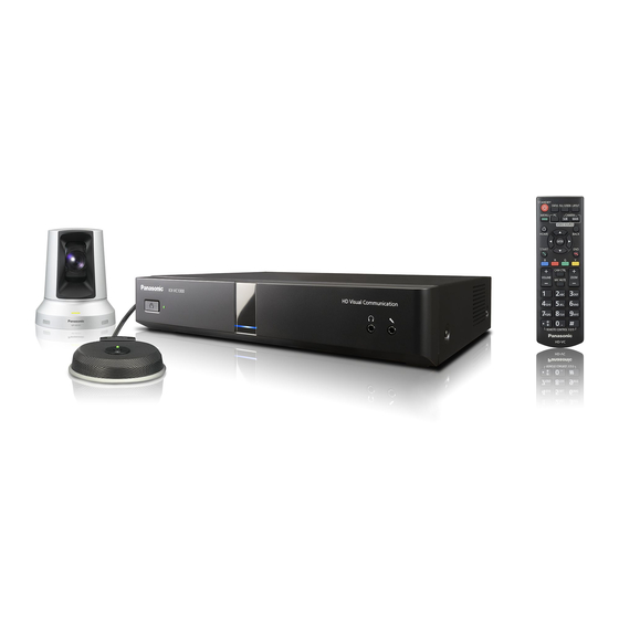
HD Visual Communication Unit
KX-VC1300/KX-VC1600
Model No.
KX-VC1300A/KX-VC1600A
User Manual
Document Version: 2015-12
Advertisement
Table of Contents

Related Manuals for Panasonic KX-VC1300


Summary of Contents for Panasonic KX-VC1300
-
Page 1: User Manual
Thank you for purchasing this Panasonic product. Please read this manual carefully before using this product and save this manual for future use. KX-VC1300/KX-VC1600: Software File Version 4.25 or later In this manual, the suffix of each model number (e.g., KX-VCA001XX) is omitted unless necessary. -
Page 2: Feature Highlights
Introduction Introduction Feature Highlights Display Display Video camera Computer Microphone Computer Display Display Internet Video camera Intranet Router Video NAT Traversal camera Service Microphone Router Microphone Lifelike Video Conference Call You can experience lifelike video conference calls with smooth, high-quality video and clear stereo sound. - Page 3 Internet. This allows seamless connectivity with units both inside and outside of your company. Multi-party connections The KX-VC1300 has a built-in MCU and can establish multiple connections with a maximum of 4 parties. The KX-VC1600 can establish multiple connections with a maximum of 6 parties standard, and is expandable to a maximum of 10 parties.
- Page 4 Introduction http://panasonic.net/psn/products/hdvc/nat_traversal/index.html This service may be unavailable depending on the country/area of use. For details, contact your dealer. This service may be unavailable depending on your router’s type or your Internet connection environment. For details, contact your dealer. IPv6 addresses cannot be used.
- Page 5 Also, some software parts of this product are licensed under the MOZILLA PUBLIC LICENSE (MPL). At least three (3) years from delivery of products, Panasonic will give to any third party who contacts us at the contact information provided below, for a charge of no more than the cost of physically distributing source code, a complete machine-readable copy of the corresponding source code and the copyright notices covered under GPL, LGPL, and MPL.
- Page 6 Introduction Portions of this software are © 1996-2012 RADVISION Ltd. All intellectual property rights in such portions of the Software and documentation are owned by RADVISION and are protected by United States copyright laws, other applicable copyright laws and international treaty provisions. RADVISION and its suppliers retain all rights not expressly granted.
-
Page 7: Table Of Contents
Table of Contents Table of Contents For Your Safety ..................11 For Your Safety .......................11 Before Operation ..................13 Notes about Operation ....................13 Data Security ........................14 Privacy and Right of Publicity ..................14 Precaution ....................15 Precaution ........................15 Preparation .....................17 Accessory/Optional Accessory Information ..............17 Optional Accessory ......................17 Part Names and Usage ....................19 Main Unit (Front) ......................19... - Page 8 Table of Contents Changing the Site Name Display (Main Site only) ............72 Changing the Audio Settings for Other Parties (Main Site only) ........72 Changing the Settings for Audio Mixing Sites (Main Site Only) .........73 Adjusting the Volume .....................74 Muting the Microphone ....................75 Reducing Microphone Noise ..................77 Displaying a Computer’s Screen and the Sub Video Camera’s Image ......78 Controlling a Video Camera ..............81...
- Page 9 Table of Contents Making Administrator Password Settings ..............125 Making Encryption Settings ..................125 Making Software Update Settings ................126 Making Connection Mode Settings ................127 Making NAT Settings ....................127 Making Call Type Settings ....................128 Making SIP Settings .....................128 Making H.323 Settings ....................130 Making Codec Settings ....................131 Making Video Output Settings ..................132 Making Audio Input/Output Settings ................134 Making GUI Settings ....................135...
- Page 10 Table of Contents Miscellaneous ..................161 Changing the Remote Control Batteries ..............161 Cleaning the Unit ......................162 Input ......................163 Inputting Letters and Numbers ..................163 Additional Information .................176 Troubleshooting ......................176 Basic Operation ......................176 Audio ..........................182 System Settings ......................184 If These Messages Appear ..................184 Registration Page of KX-VC Series NAT Traversal Service ........190 KX-VC Series NAT Traversal Service for this Device ..........191 If a message from the KX-VC Series NAT Traversal Service is displayed ....192...
-
Page 11: For Your Safety
R6 (AA) type dry cell. intended to alert the user to the presence of uninsulated "dangerous voltage" within For use only with power supply Panasonic, the product’s enclosure that may be of PGLV1006. (KX-VC1300/KX-VC1600/ sufficient magnitude to constitute a risk of KX-VC1300SX/KX-VC1600SX) electric shock to persons. - Page 12 For Your Safety Refer all servicing to qualified service personnel. Servicing is required when the apparatus has been damaged in any way, such as power-supply cord or plug is damaged, liquid has been spilled or objects have fallen into the apparatus, the apparatus has been exposed to rain or moisture, does not operate normally, or has been dropped.
-
Page 13: Before Operation
Before Operation Before Operation Notes about Operation Avoid placing the device in areas with high humidity, and exposing it to rain. Neither the main unit nor the power plug is water Please pay attention to the following points when using resistant. -
Page 14: Data Security
By installing and using this device, you are responsible Panasonic is not responsible for any damages for maintaining the privacy and usage rights of images caused by improper use of this device. -
Page 15: Precaution
A replacement fuse and the environment. cover can be purchased from your local Panasonic For more information about collection and dealer. recycling, please contact your local municipality. - Page 16 This equipment is not for use at video display work stations according to BildscharbV. Disposal may be regulated in your community due to environmental considerations. For disposal or recycling information, please visit Panasonic website: http:// www.panasonic.com/environmental or call 1-888-769-0149. User Manual...
-
Page 17: Preparation
Preparation Preparation Accessory/Optional Accessory Information The following accessories are included: Included Accessories Accessories Quantity AC adaptor Part No.:PGLV1006 (KX-VC1300/KX-VC1600/KX-VC1300SX/ KX-VC1600SX) Part No.:PGLV1011 (KX-VC1300A/KX-VC1600A) Power cord Depends on country/area Remote control Part No.: N2QAYB001001 Batteries (R6 [AA] dry cell) Note •... - Page 18 "Activating Enhanced Features" (Page 138). Activation Model No. Product Name Target Model Description Key Type Extends the service Activation Key Card KX-VC1300 period of KX-VC KX-VCS701 Traversal 1 (NAT Traversal 1 Year) KX-VC1600 Series NAT Traversal Year Service. Extends the service...
-
Page 19: Part Names And Usage
Preparation Part Names and Usage Main Unit (Front) Power LED Shows the power status. The LED is green or red when power is being supplied from the AC adapter, and off when power is not being supplied. Remote Control Signal Receiver Receives Remote Control signals. -
Page 20: Main Unit (Back)
Preparation Main Unit (Back) KX-VC1600 KX-VC1300 Camera Control terminal Not used. RS-232C terminal Normally not used. Used to connect a computer for maintenance. USB jack (Page 136, Page 139) Used to connect a USB memory device for saving the operation log and for updating the software. - Page 21 Preparation HDMI terminal (Page 31) Used to connect a computer for sending screens to participants. Sub Camera terminal (Page 31) Used to connect a second, sub video camera with an HDMI cable for sharing video contents apart from the main video camera. Main Camera terminal (Page 27) Connect the main video camera with an HDMI cable.
-
Page 22: Remote Control
Preparation Remote Control Press to enter screen standby mode (Page 24). The power of the unit can be turned on/off by pressing and holding (for 1 second). During communication, the power of the main unit cannot be turned off. Press to show your computer’s screen on your and the other party’s display during a video conference call. When not on a video conference call, the computer screen is shown on your display only (Page 78). - Page 23 Preparation Press to return to the previous screen. Press to confirm the selected item or entered information. Press to end a video conference call. Press to display the camera control screen (Page 82). Press for zoom control (zoom in/out) of the video camera either at your end or the other party’s end (Page 81).
-
Page 24: Led Indication
Preparation LED Indication LEDs indicate the operational status of the unit, as follows: Power Status LED Status • AC power: OFF (Without power supplied from the AC adapter) • Red on AC power: ON (Power button: OFF) Green Blue flashing •... - Page 25 Preparation • It takes about 7 seconds to return from screen standby mode. (The length of time may vary depending on the type of display you are using.) Document Version 2015-12 User Manual...
-
Page 26: Connection And Preparation
Preparation Stereo pin plug cable (for connecting a Connection and general-purpose microphone/amplifier/active Preparation speaker/display [without an HDMI terminal and with speakers]): RCA plug Device and Network Connection Network Environment In addition to the unit, you will need a video camera, a When using the unit over the Internet, a broadband display, a microphone (Boundary Microphone or connection is required. -
Page 27: Connecting The Unit
Preparation Notice Connecting the Unit • Use only the included power cord. This section describes how to connect the main video Note camera, display, microphone, LAN cable, AC adaptor and power cord. • Make sure to read the instruction manuals for all devices being connected. - Page 28 Preparation System Layout Examples the cable. When you disconnect the cable, grip the connector securely and pull it out. Display and Main Video Camera General-purpose microphone Place the display and main video camera at the same Connect the microphone to the Audio In L/R jack on side of the room.
- Page 29 Preparation • Layout examples (a regular room) Do not connect more than 4 Digital Boundary (the grey circle indicates the microphone’s range): Microphones. Doing so will cause all Digital Boundary Microphones to stop working. If an Analogue Boundary Microphone is also connected, all audio input from the Analogue Boundary Microphone will also stop working.
- Page 30 Preparation Noise A quiet A regular A noisy level/ room room room Micro– (13.1 ft) (13.1 ft) phone dBsplA) dBsplA) dBsplA) Display Microphone Microphone approx. approx. approx. 1.5 m (approx. (approx. (approx. 6.5 ft) 4.9 ft) 3.3 ft) (13.1 ft) (13.1 ft) Microphone Microphone...
- Page 31 Preparation Sub Video Camera Connection Headset Connection You can connect a headset to the headset jack on the This section describes how to connect a sub video front of the unit. camera. You can transmit images taken with the sub video camera to all parties.
- Page 32 Preparation Amplifier/Active Speaker • For computers without HDMI ports, connect the computer to the RGB terminal on the back of the Connection unit using a VGA cable. This section describes how to connect an amplifier/ active speaker. Note • Connect the amplifier/active speaker to the Audio You can connect/disconnect the computer Out L/R jack on the back of the unit using a stereo during a video conference call.
- Page 33 Preparation Connecting the Display with a Component Cable If your display does not have an HDMI terminal, use a component cable for connection. Connect the display to the Component terminal on the back of the unit using a component cable. Note •...
-
Page 34: Network Configuration Example
Preparation Network Configuration Example Diagram (when using the Internet/KX-VC Series NAT Traversal Service) Compatible with LAN1 KX-VC Series NAT Traversal Service Router LAN1 Internet Router Router User Manual Document Version 2015-12... - Page 35 Preparation Diagram (when using an intranet/KX-VC Series NAT Traversal Service) Compatible with LAN1 and LAN2 (KX-VC1600 only) Intranet Router KX-VC Series NAT Traversal Service LAN2 LAN1 Internet Router Router Note When using a dual network (LAN1 and LAN2) • Use LAN1 when using KX-VC Series NAT Traversal Service. •...
-
Page 36: Preparing The Remote Control
Preparation Preparing the Remote Control Inserting Batteries Open the cover. Insert batteries (R6 [AA] dry cell), minus side first, then close the cover. User Manual Document Version 2015-12... -
Page 37: Turning The Power On/Off
Preparation Turning the Power On/Off Note • Make sure that peripheral devices (e.g., display, main video camera) are turned on. • When you turn the power on for the first time, the Initial Settings screen is displayed (Page 44). Press the Power button on the front of the unit or on the remote control for more than 1 second. -
Page 38: Screen Display
Preparation Screen Display Home Screen (Idle Screen) Displayed when the power is turned on. Also displayed when the [HOME] button is pressed on the remote control. Main Video Camera Image Displays the video from the main video camera. Unit Information The information displayed differs depending on the selected connection mode (Page 127). - Page 39 Preparation Icon Status of Settings When using IP mode: "SIP" is set to "ON" and "Encryption (SIP)" is set to "ON". When using NAT Traversal mode or IP/NAT Traversal mode: "Encryption (SIP)" is set to "ON". When using IP mode: "SIP" is set to "ON" and "Encryption (SIP)" is set to "OFF".
-
Page 40: Menu Screen (Idle Screen)
Preparation Icon Status Microphone is muted. Network, server (any kind), or peripheral connection error (no connection, device error, etc.). Note • If there are no connections, or there is a device error in other devices such as the LAN cable, the icon will be displayed. Note •... -
Page 41: Video Conference Call Screen
Preparation Video Conference Call Screen Other party’s information When using IP mode: When registered in the contact list: The other party’s name/IP address is displayed. When not registered in the contact list: The other party’s IP address, SIP URI (SIP user name@SIP domain name), host name (e.g., hdvc.example.com), H.323 extension, H.323 name, MCU’s conference room number@IP address, or MCU’s SIP user name@IP address is displayed. - Page 42 Preparation Note • If the icon shows only 0–1 bars continuously, contact your network administrator. • During multiple-party video conference calls, the icon is displayed on each site screen, but not on your own image. • You can set whether to display the icon. This setting affects all displayed images (excluding your own image) (Page 110).
-
Page 43: Entering Characters
Preparation Entering characters You can use the remote control to input letters and numbers. • Note the following regarding entering the address of the other party. – SIP user name/MCU’s conference room number: alphanumeric characters, symbols . = * + _ - $ ! ? / ( ) ' (up to 60 characters) –... -
Page 44: Initial Settings
Preparation Initial Settings Press [ENTER], use [ ] to select the desired connection mode, and then press [ENTER] again. Note • The Initial Settings screen is displayed when you turn the power on for the first time. It will not be displayed again afterwards. - Page 45 Note – "Manual": Set the IP address information manually. • For the KX-VC1300, "IP Address (LAN 1)" (setting), "IP Address (LAN 1)", and Note "Subnet mask (LAN 1)" are respectively • To select "Auto", "IP Address (LAN displayed as "IP Address" (setting), "IP 1)"...
- Page 46 Preparation • If the value for "Primary DNS Server" or "Secondary DNS Server" contains 1 or 2 digits numbers, enter these numbers as they are. Do not enter like [.001]. Example: The IP address is [192.168.0.1]. – Correct entry: [192.168.0.1] –...
-
Page 47: Starting A Video Conference
Starting a Video Conference Making a Video Conference Call You can make a video conference call using one of the following methods. Note • Make sure that peripheral devices (e.g., display, main video camera) are turned on. • If a called party does not answer a video conference call within approximately 60 seconds, the call will be terminated automatically. -
Page 48: Calling From The Contact List (2-Party Conference)
Starting a Video Conference Calling from the Contact List (2-party Conference) Note • To make a video conference call from the contact list, you must first register contacts in the contact list (Page 94). • If "IP Address (LAN 1)" (setting) is set to "Auto" on the network settings screen (Page 106), or if "IPv6 Address (LAN 1)"... - Page 49 Starting a Video Conference Select the entry you want to call using [ • You can switch the index tab back and forth using ]. (Index tabs in which no entries exist will be skipped.) • Press a numeric button on the remote control to switch to the index tab assigned to that button, as shown below.
-
Page 50: Calling Using Profile (Multiple-Party Video Conference Calls)
Starting a Video Conference Calling Using Profile (Multiple-party Video Conference Calls) When making multiple-party video conference calls from the Menu screen, you can make a call using one of 20 profiles (1 to 20). Note • To call using a profile, you need to have a profile programmed in profile settings in advance (Page 97). - Page 51 Starting a Video Conference Press [B]. • The profile settings screen is displayed. Select "Site" using [ ], then press [ENTER]. • The screen for selecting the party you want to call from the profile is displayed. Select the party using [ ], then press [ENTER].
-
Page 52: Calling By Entering An Address Directly
Starting a Video Conference Calling by Entering an Address Directly When using IP mode, you can make a video conference call by entering the IP address (or host name), SIP URI (or SIP user name), H.323 extension, H.323 name, or MCU’s conference room number@IP address. When using NAT Traversal mode, you can make a call by entering the connection number. - Page 53 Note • When using the KX-VC1300, you can have video conference calls with a maximum of 3 parties simultaneously. When you are using the KX-VC1600, the maximum is 5 simultaneous parties, and if you have the activation key card (KX-VCS304) for enhanced features, you can make multiple-party video conference calls with a maximum of 9 parties.
- Page 54 Starting a Video Conference Press [ENTER]. • When using H.323, you can also call by entering the other party’s IP address (or host name) %H.323 extension (or H.323 name). • When the called party was selected from the contact list, the site name for the other party is displayed. •...
-
Page 55: Calling From The Call History
• When connecting to a non-Panasonic video conference system, you may not be able to initiate video conference calls with SIP URIs (or SIP user names)/H.323 extension/H.323 name in the incoming call history. In this case, contact your network administrator. - Page 56 Starting a Video Conference Press [MENU]. • The Menu screen is displayed. Select "Call History" using [ ] and press [ENTER]. • The outgoing call history screen is displayed. 2, 3 4, 5 Note • The result of the video conference call is displayed in the "Call result"...
- Page 57 Starting a Video Conference • When a contact in the incoming call history is newly added to your contact list, the incoming call history will be updated to display the contact’s information from the contact list. • When a party that is not registered in your contact list is selected, if you press [B], the contact list registration screen will be displayed and a new contact can be registered (Page 96).
-
Page 58: Answering A Video Conference Call
Starting a Video Conference Answering a Video Conference Call Depending on your setting, you can respond to a request to participate in a video conference call manually (manual answer), automatically (automatic answer), or forcibly (forced answer) (Page 109). Note • Make sure that peripheral devices (e.g., display, main video camera) are turned on. - Page 59 Starting a Video Conference Note • If you do not answer a video conference call within approximately 60 seconds, the call will be terminated automatically. • If a video conference call is received while making a video conference call, a dialogue box to confirm if you answer a video conference call is displayed (only when "More than one incoming call"...
-
Page 60: Connecting To An Mcu
Starting a Video Conference Connecting to an MCU Connecting to an MCU allows you to have a video conference call with 10 or more parties. Intranet Note • MCUs you want to connect to must meet the following criteria. Confirm the settings of the MCU. –... - Page 61 If the other party sends tone signals to you, sound may be interrupted or a ringing noise may occur. • You can operate the other party’s device using tone signals with the KX-VC1600/KX-VC1300/ HDVC-MPCS. Enter a tone signal (0–9, #, or •...
-
Page 62: During Video Conference Calls
During Video Conference Calls Adding Parties to an Existing Video Conference Call (Except Sub Sites) A site in a 2-party video conference call or the Main Site can use the following operations to add parties to an existing call. Press [MENU]. •... - Page 63 During Video Conference Calls When selecting manual dial: • The manual dial screen is displayed. 1. Program the information of the other party whom you want to add using [ Note • You can refer to the contact list or call history when entering the other party’s information. Press [G].
-
Page 64: Disconnecting Parties During Video Conference Call
During Video Conference Calls Disconnecting Parties During Video Conference Call You can disconnect parties during a video conference call. Disconnecting a 2-party conference Press [END]. • The video conference call is disconnected. Disconnecting a multi-party conference (Main Site only) Press [END]. •... -
Page 65: Changing The Contents Sharing Method During Communication
During Video Conference Calls Changing the Contents Sharing Method During Communication The method for sending contents during communication can be changed. Note • The method for sending contents cannot be changed while contents are being sent. Press [MENU]. • The communication menu screen is displayed. Use [ ] to select "Send Cont Method", and press [ENTER]. -
Page 66: Changing The Screen Layout During A Video Conference Call
During Video Conference Calls Changing the Screen Layout during a Video Conference Call You can change the layout of the screen during a video conference call. Note • Display patterns differ depending on the number of displays, the number of parties, whether to share contents or not, whether it is Main Site or Sub Site, and whether the communication is single stream or dual stream. - Page 67 During Video Conference Calls Use [ ] to select "Screen mode set." and press [ENTER]. • The layout settings dialog box is displayed. Use [ ] to select a layout to set, and press [ENTER]. – "Auto": Automatically changes the layout depending on the number of parties joining a video conference call and the MCU mode (Page 69, Page 97, Page 111).
- Page 68 During Video Conference Calls Layout patterns that can be selected during a video conference call Layout Number Layout Configuration CP10 Operation of Sub Sites During a video conference call, you can use remote control operations to change the screen display layout from a Sub Site.
-
Page 69: Changing The Mcu Mode (Main Site Only)
During Video Conference Calls Numerical Keypad Layout Number CP10 Note • If "DTMF layout change" in "MCU Settings" is set to "OFF", operations cannot be performed from a Sub Site (Page 113). • When the layout is changed from a Sub Site, all sites’ layouts are also changed. •... -
Page 70: Changing The Setting Of The Main Display (Main Site Only)
During Video Conference Calls Changing the Setting of the Main Display (Main Site only) The settings of the site displayed as the main site during a call can be changed. Press [MENU]. • The communication menu screen is displayed. Use [ ] to select "Main Position set."... - Page 71 During Video Conference Calls Use [ ] to select "Done" and press [ENTER]. Note • When sharing content via single stream communication, the content will automatically displayed as the main display. Document Version 2015-12 User Manual...
-
Page 72: Changing The Site Name Display (Main Site Only)
During Video Conference Calls Changing the Site Name Display (Main Site only) The setting of whether site names are displayed during a video conference call can be changed. Press [MENU]. • The communication menu screen is displayed. Use [ ] to select "Site name display" and press [ENTER]. •... -
Page 73: Changing The Settings For Audio Mixing Sites (Main Site Only)
During Video Conference Calls Changing the Settings for Audio Mixing Sites (Main Site Only) When "Other Site's Audio" is set to "Mix (Selection)", you can change the audio settings for sites whose audio is mixed together. (Page 72, Page 97) Press [MENU]. -
Page 74: Adjusting The Volume
During Video Conference Calls Adjusting the Volume You can adjust the volume during a video conference call. Press [VOLUME (+/–)]. • The volume level bar is displayed at the bottom of the screen. Adjust the volume using [VOLUME (+/–)]. • Pressing [+] will increase the volume of the other party’s voice. -
Page 75: Muting The Microphone
During Video Conference Calls Muting the Microphone During a video conference call, you can mute the microphone so that your voice cannot be heard by the other party. You will be able to hear the other party’s voice, but they will not be able to hear you. Note •... - Page 76 During Video Conference Calls Muting the Microphone (Operation with the Boundary Microphone) Press the MIC Mute button. • An icon appears in the status display area of the screen (Page 38), and the LED light on the Boundary Microphone becomes red. Make sure the colour of the LED changes.
-
Page 77: Reducing Microphone Noise
During Video Conference Calls Reducing Microphone Noise You can reduce the amount of ambient noise picked up by the microphone (shuffling of papers, etc.) during a video conference call. When noise reduction is in effect, the volume level of voices may also be reduced. Press [Y]. -
Page 78: Displaying A Computer's Screen And The Sub Video Camera's Image
During Video Conference Calls Displaying a Computer’s Screen and the Sub Video Camera’s Image When a computer or sub video camera is connected to the unit, you can display the computer’s screen or the sub video camera’s image on your display and to other parties. This is convenient when explaining something on the computer’s screen or the sub video camera’s image while showing them to others, for example. - Page 79 During Video Conference Calls Example: single stream communication (2 screens Example: dual stream communication (2 screens used, 4-party video conference, at the Main Site) used, 4-party video conference, at the Main Site) Without contents Without contents sharing sharing HDMI1 HDMI2 HDMI1 HDMI2 Site 1...
- Page 80 During Video Conference Calls Note • Pressing [LAYOUT] in succession will switch the displays of the 2 monitors in different combinations of the contents image display, the contents image combined with the camera image, and the camera image display. • For single stream communication: –...
-
Page 81: Controlling A Video Camera
The features that can be used may be limited depending on your video camera model. (e.g., A video camera with only a zoom feature) • When the other party is using a non-Panasonic video conference system, some operations may not be available, or unintended operations may occur. •... - Page 82 Controlling a Video Camera Note • Your own video camera’s image will be displayed when operations are performed during a call so that you can confirm the operations. If no operation is made for approximately 3 seconds, the original screen is displayed.
- Page 83 Controlling a Video Camera Press the buttons on the remote control to operate the video camera. [ZOOM (+/-)]: Zoom in/zoom out ]: Pan the video camera left/right. ]: Tilt the video camera up/down. • The movement continues as long as you hold down the button, and stops when you release the button.
-
Page 84: Registering A Preset
Controlling a Video Camera Registering a Preset When you are not on a video conference call, you can register up to 9 presets (pan, tilt, zoom position, etc.) of the video camera connected as the main or sub video camera on your side. Note •... - Page 85 Controlling a Video Camera Press a numeric button (1–9) to select the preset number to use. • The selected preset number is displayed in the upper right corner of the screen. Note • When a preset number that has already been registered is selected and preset registration is performed, that preset’s registered information will be overwritten.
-
Page 86: Recalling A Registered Preset
Controlling a Video Camera Recalling a Registered Preset During a video conference call, you can set your own video camera’s direction, zoom and magnifier settings, etc., to the desired state by selecting a registered preset. Note • For details about compatible video camera models, contact your dealer. •... -
Page 87: Changing Video Camera Settings
Controlling a Video Camera Changing Video Camera Settings Whether or not you are on a video conference call, you can set the brightness and white balance, etc., of the video camera connected as the main or sub video camera on your side. Note •... - Page 88 Controlling a Video Camera Press [MENU]. • The camera menu screen is displayed. Use [ ] to select the item you want to set, and press [ENTER]. • The setting screen for the selected item is displayed. Note • Some items may not be displayed depending on your video camera model.
- Page 89 Controlling a Video Camera "White Balance" screen This function adjusts the colour so that white colours always appear white under various types of light sources. "White Balance": Press [ENTER] and use [ ] to select the desired value for the white balance ("Auto", "Indoor 1", "Indoor 2", "Outdoor (Sunny)", "Outdoor (Cloudy)", or "Calibrate").
- Page 90 Controlling a Video Camera "Digital Zoom" screen This function crops the centre part of the video image and enlarges it through digital processing. "Digital Zoom": Press [ENTER] and use [ ] to select "ON" or "OFF". "Magnifier Settings" screen This function crops a part of the video image and displays it in the four corners of the screen.
- Page 91 Controlling a Video Camera Configure the advanced settings of the magnifier by pressing the [G] button on the remote control. Note • The magnifier settings can be registered as a preset (Page 84). (To change which position to magnify): If you want to change which content to magnify, adjust the magnification position by pressing ] to move the frame that indicates the area to magnify.
-
Page 92: Displaying The Connection Status
Displaying the Connection Status Displaying the Connection Status You can confirm the connection status of the network and peripheral devices. Press [STATUS]. • The connections status screen is displayed. A "–" mark is displayed next to any network or peripheral devices connection that is not in normal operation or not connected. -
Page 93: Displaying Unit Information
Displaying the Connection Status Displaying Unit Information Note • Describes the information displayed for devices other than those that are currently being used in a multicast. For the display of information for devices that are currently being used in a multicast, refer to "Confirming the Transmission Status During a Multicast (Multicast Terminal) (Page 159)"... -
Page 94: Contacts And Settings
Contacts and Settings Contacts and Settings Adding Contacts to the Use [ ] to select the following items for input: "Site": Enter a name for the contact (up to 24 Contact List characters) (Page 163). "Speed Dial": Enter a speed dial number (1–600). "Max. -
Page 95: Editing Contact Information
Contacts and Settings SIP domain name must be entered along Press [G]. with their SIP user name. • The contact list edit screen is displayed. • If the SIP domain name is not entered, your own SIP domain name is automatically appended to the registered contact. -
Page 96: Registering A Contact From The Call History
Contacts and Settings Use [ ] to select "Contact List" and press Use [ ] to select the single-party entry you [ENTER]. • want to add as a contact, and press [B]. The contact list screen is displayed. • The contact list registration screen is displayed. Use [ ] to select the contact you want to delete. -
Page 97: Registering A Profile
Contacts and Settings – Registering a Profile "OFF" (default): Entry to conference rooms is not restricted. "Site name display": Use [ ] to select You can register the settings required for starting for a whether to display site names during a video conference call in advance as a profile, including multiple-party connection. - Page 98 Contacts and Settings "Screen Layout (Presentation)": Press [ENTER] determined by their priority, which is determined by the "Site" ID assigned to and use [ ] to select the screen layout for their profile settings (lower IDs have Presentation Mode. priority). –...
- Page 99 Contacts and Settings Note • The site selection screen is displayed. • If there are no registered contacts with a When selecting "Call History": " " mark in the selection column, a call will • The outgoing call history selection screen is not be made even if [START] is pressed.
-
Page 100: Editing Profile Information
Contacts and Settings Deleting a Profile Press [HOME]. • The Home screen is displayed. Press [MENU]. • The Menu screen is displayed. Note • To continue entering another profile, press [B] Use [ ] to select "Profile" and press from the profile list and repeat steps 3-13. [ENTER]. -
Page 101: Making Local Site Settings
Contacts and Settings "Name": Enter a device name for the local site. Making Local Site "Connection mode": Press [ENTER] and use Settings ] to select a connection mode (IP Mode, NAT Traversal Mode, IP / NAT Traversal Mode) (default: "IP Mode"). You can register up to 10 local sites. -
Page 102: Deleting Local Site Information
Contacts and Settings Use [ ] to select "Yes" and press [ENTER]. Press [HOME]. • The unit restarts automatically. • The Home screen is displayed. Note • When changing the connection mode, the time required for a restart may depend on network conditions. -
Page 103: Changing System Settings/Performing System Maintenance
Contacts and Settings Changing System Settings/Performing System Maintenance You can set, change, and confirm the unit’s various function settings. Note • If a video conference call is received while data is being entered, a dialogue box to confirm if you answer a video conference call is displayed. - Page 104 Contacts and Settings One-Touch Set.: Sets the one-touch connection numbers displayed on the Home screen (Page 113). Standby Setting: Sets the time until screen standby mode is activated (Page 113). Sound Settings: Sets the sounds played at startup and when a video conference call starts (Page 114).
- Page 105 Contacts and Settings Admin login: Shifts to the settings screen for the administrator menu (Page 121). System Info.: You can display the setting information of the main unit (Page 118). Enhancement: You can check the features that have been enabled due to the software enhancement feature (Page 118).
-
Page 106: Setting The Unit Name
Contacts and Settings Note Setting the Unit Name • For the KX-VC1300, "IP Address (LAN Select "System Settings" and press [ENTER]. 1)" (setting), "IP Address (LAN 1)", and • The unit name setting screen is displayed. "Subnet mask (LAN 1)" are respectively displayed as "IP Address"... - Page 107 For the input format for "IPv6 Address Note (LAN 1)" and "Default Gateway (IPv6)", refer to Page 43. • For the KX-VC1300, "IPv6 (LAN 1)", "IPv6 • For "IPv6 Address (LAN 1)", set your Address (LAN 1)" (setting), "IPv6 network’s global address.
- Page 108 Contacts and Settings "Secondary DNS Server (IPv6)": Enter the IPv6 settings and close the setting screen. Then, address of the secondary DNS server for IPv6. select "Network Settings" and set the routing. Note • For the input format for "Primary DNS Routing settings for LAN2 (KX-VC1600 only) Server (IPv6)"...
-
Page 109: Making Connection Settings
(default: "Not Specified"). Making Connection Settings Note Note • For the KX-VC1300, "Max. Bandwidth Per • You can use the administrator menu to hide the Site (LAN 1)" is displayed as "Max. connection settings screen (Page 135). Bandwidth Per Site". - Page 110 Contacts and Settings – "Video Quality": Press [ENTER] and use [ "OFF": Boundary Microphone/headset detection is disabled. ] to select between prioritising smooth movement or image quality for video. Note – "Motion" (default): Prioritise smooth • When Boundary Microphones/headsets are movement.
-
Page 111: Setting The Mcu
Contacts and Settings to become unable to communicate with only. This mode is suited to lecture-style other parties. conferences. • "Screen Layout (Discussion)": Press [ENTER] Be aware that if encryption is disabled, eavesdropping might be possible on and use [ ] to select the screen layout for networks that are not secured against such Discussion Mode. - Page 112 Contacts and Settings "Main Position (Discussion)": Press [ENTER] Layout Number Layout Configuration and use [ ] to select the display method for the main position. – "Local Site" (default): Displays your own site. – "Voice Activation 1": The site with the loudest volume is automatically displayed as the main display.
-
Page 113: Setting One-Touch Connection Numbers
Contacts and Settings Setting One-touch Connection "DTMF layout change": Use [ ] to select whether other parties can use remote control Numbers operations to perform screen layout change operations. Set the addresses or profiles assigned to the one-touch – "ON": Enable operations by Sub Sites using the connection numbers (1 to 5) displayed on the home remote control. -
Page 114: Making Sound Settings
Contacts and Settings "Standard" [default], "More Lows", "Voice" or Select "Standby Setting" and press [ENTER]. "Music") at the start of a video conference call. • The screen standby settings screen is displayed. Note • You can listen to a sample of the following Enter the length of time (0–99) in minutes until the items by pressing [R]. - Page 115 Contacts and Settings Note • For the settings shown in the following diagrams, the left/right channels are • Depending on how many Digital Boundary displayed as viewed from the side of the Microphones are connected, the output main video camera. settings differ as follows: –...
-
Page 116: Making Remote Control Settings
Contacts and Settings When setting Digital Boundary Microphones as Making Remote Control follows: Settings Display Main video camera You can specify a remote control ID from 1, 2, or 3 for Speaker Speaker both the remote control and the unit. The unit responds to signals from any remote control with the same remote control ID as itself. -
Page 117: Changing Video Camera Settings
Contacts and Settings Note – "OFF": Do not allow camera operations using the remote control. • While the dialogue box is displayed, video "Direct Cam Ctrl on Home Screen": Use [ conference calls cannot be received. ] to select whether camera operation by remote control is enabled when not in a video conference When "Remote ID enable"... -
Page 118: Using Multicast
Contacts and Settings Press [ENTER] and use [ ] to select the Select "System Info." and press [ENTER]. • desired language. The unit information screen is displayed (Page 93). Note • The language you can select is as follows: "English": English (default), "Deutsch": German, "Français": French, "Italiano": Italian, "Español": Spanish, "Nederlands": Dutch, "Português":... -
Page 119: Performing A Network Test
Contacts and Settings Performing a Network Test • Set the microphone at least 1 m (3.3 ft) away from the speakers. You can confirm whether a network connection can be established with a particular IP address. Press [R]. • The self diagnosis starts. Note •... -
Page 120: Performing Remote Maintenance
Contacts and Settings Select "EULA" and press [ENTER]. • The End-User Licence Agreement display screen is displayed. Press [BACK]. • The system setting screen is displayed. Performing Remote Maintenance The following operation is for performing remote maintenance by your dealer. After performing the operation, you cannot use the unit until remote maintenance is finished. -
Page 121: Making Administrator Menu Settings
Contacts and Settings Making Administrator Menu Settings Administrator Menu List You can set, change, and confirm the unit’s administrator functions. Note • If a video conference call is received while data is being entered, a dialogue box to confirm if you answer a video conference call is displayed. - Page 122 Contacts and Settings Note • You can display the login screen by pressing [Y] in the Menu screen instead of performing steps 1–4. • Please enter the administrator password that was set during installation. • If you forget the administrator password, please contact your dealer. Use [ ] to select "Login"...
- Page 123 Contacts and Settings Video Output: Sets HDMI and analogue component video output (Page 132). Audio I/O: Sets audio settings (Page 134). GUI Settings: Sets which items are displayed on the menu screens and other screens (Page 135). HDMI Settings: Sets the enabling/disabling of control via HDMI (Page 135).
- Page 124 Contacts and Settings Enhancement: Activates registration keys used for enhancing the features of the device (Page 138). Version Confirmation: Updates the software from a USB memory device (Page 139). Camera Initialize: Initialises your own site’s video camera (Page 140). System Initialize: Initialises all settings apart from those for functions enabled from enhanced software (Page 140).
-
Page 125: Making Administrator Password Settings
Contacts and Settings • Making Administrator If an encryption key is not set for SIP communication, you cannot enable encryption. Password Settings • When using encrypted communication with the KX-VC Series NAT Traversal Service, set SIP Select "Password Settings" and press [ENTER]. communication encryption using this setting. -
Page 126: Making Software Update Settings
Contacts and Settings – Making Software Update "OFF" (default): Encryption is disabled. "Encryption Key (SIP)": Enter an encryption key Settings (4 to 256 characters [alphanumeric, space, symbols]) (Page 163). Preparation settings for updating the software can be Note made here. •... -
Page 127: Making Connection Mode Settings
Traversal Service, refer to the following web • To select "ON", "H.460" must be set to site: "OFF" on the H.323 settings screen http://panasonic.net/psn/products/hdvc/ (Page 130). nat_traversal/index.html • When "ON" is selected, the IP address of the WAN side will be displayed for the unit Press [G]. -
Page 128: Making Call Type Settings
Contacts and Settings Making Call Type Settings "Conversion IP and Port Num.": Use [ ] to select "ON" or "OFF" (default). Select "Call Type Settings" and press [ENTER]. Note • The call type settings screen is displayed. • When using a router that features Symmetric NAT to connect to a mobile Use [ ] to select the following items for input:... - Page 129 • • Video conference calls to an MCU or a Enter a standards-compliant value. For non-Panasonic video conference system details, contact your network administrator. through a SIP server using a SIP URI are not "Digest Authentication": Use [ ] to select guaranteed.
-
Page 130: Making H.323 Settings
Contacts and Settings • Press [G]. The DNS server setting is necessary to • enter host names (Page 106). A dialogue box to confirm the saving of settings • is displayed. See Page 43 for details about the characters that can be input for host names. Use [ ] to select "Yes"... -
Page 131: Making Codec Settings
Contacts and Settings Making Codec Settings These settings determine which codecs are enabled and disabled. Note • Changing codec settings may affect the ability to make and receive calls. For details, contact your dealer. • If "NAT Traversal Mode" is selected in the connection mode settings, codec settings will not be displayed. -
Page 132: Making Video Output Settings
Contacts and Settings contents are shared during dual stream Making Video Output Settings communication. – "Content" (default): Displays your own shared Sets video output to HDMI. contents. Select "Video Output" and press [ENTER]. – "Content / Other (PwithP)": Displays your own •... - Page 133 Contacts and Settings – "Content / Other" (default): Displays your own output and an HDMI output equivalent to shared contents using HDMI1, and the image of analogue component. the other party using HDMI2. "Display position of local site": Press [ENTER] –...
-
Page 134: Making Audio Input/Output Settings
Contacts and Settings – Making Audio Input/Output "HDMI1" (default): Outputs audio from HDMI1. – "HDMI2": Outputs audio from HDMI2. Settings – "OFF": Audio is not output to HDMI. Note Note • • In the image output settings, when "Video These settings are for adjusting the audio Output"... -
Page 135: Making Gui Settings
Contacts and Settings • If you select "OFF", the guide is not displayed Press [G]. in the Home screen. Pressing [FULL • SCREEN] on the remote control will switch A dialogue box to confirm the saving of settings between displaying/hiding. is displayed. -
Page 136: Setting Shortcuts
Contacts and Settings Note Use [ ] to select the following items for input: "One Touch Play": Use [ ] to select "ON" or • Items set to "OFF" in "GUI Settings" are also displayed. "OFF" (default). Press [G]. Note •... -
Page 137: Importing Data
Contacts and Settings log can be used to specify the cause when problems Note occur. For details, contact your dealer. • While the data is being exported, do not remove the USB memory device. This could Note damage the unit or corrupt the data. •... -
Page 138: Activating Enhanced Features
Contacts and Settings • "Encryption Data", "Startup screen", or The following types of USB memory devices "Multicast Tree List". cannot be used: – U3 smart drives (USB memory devices Press [G]. compatible with the U3 platform) • – A dialogue box is displayed asking you to USB memory devices with security features confirm the import and that unit will restart after –... -
Page 139: Updating Software
Contacts and Settings – Updating Software "Expired": Less than 6 months have passed since the service expiration date. The service period can be Note extended. • If you want to update software using a USB – "Expiration date is <Day/Month/ memory device, consult your dealer. -
Page 140: Initialising A Video Camera
Contacts and Settings Note Initialising a Video Camera • Please carefully read and confirm the cautions in the dialogue box before Note proceeding to the next step. • Initialisation is available only for video cameras connected to your unit and only when you are Use [ ] to select "Yes"... -
Page 141: Using The Kx-Vc Series Nat Traversal Service
Using the KX-VC Series NAT Traversal Service Using the KX-VC Series NAT Traversal Service Using the KX-VC Series NAT Traversal Service Preparations for Connections Service Period Overview To use this service, registration is necessary. By registering using the activation key included with the product, you can use this service for 3 months at no charge. - Page 142 Using the KX-VC Series NAT Traversal Service Obtain a Registration Key (Page 143) (using a computer) Perform the settings necessary for using the KX-VC Series NAT Traversal Service (Page 127). (Unit operations) Register the Registration Key (Page 138) (using the unit) Video conference call over KX-VC Series NAT Traversal Service Extend the Service Period of KX-VC Series NAT Traversal Service (Page 146) (using a computer)
-
Page 143: Connect To The Internet
– Recorded on an activation key. Router Please use a router that has been tested by Panasonic To check the MPR ID (using the for use with this service, and use the information from your provider to connect to the Internet. For details... -
Page 144: To Obtain A Registration Key (Using A Computer)
Using the KX-VC Series NAT Traversal Service To obtain a Registration Key Click "Apply new" next to HDVC. (using a computer) Note • The following operating systems and web browsers are supported: Microsoft Windows ® ® – Microsoft Windows Internet Explorer ®... -
Page 145: To Display The Registration Key Again (Using A Computer)
Using the KX-VC Series NAT Traversal Service • To display the Registration Key The information confirmation screen is displayed. again (using a computer) Note If you misplace the Registration Key information, you • Clicking "Click to Show next Terminal can display it again by following the procedure below. IDs"... - Page 146 Using the KX-VC Series NAT Traversal Service Extending the Service Period "Activation Key No." "Registration ID" To extend the service period, it is necessary to purchase an activation key. The duration of the Click "Next". extension differs according to the card purchased. For •...
- Page 147 Using the KX-VC Series NAT Traversal Service Enter the characters displayed in the image, and "Activation Key No.": Input the Activation Key No. then click "Apply". printed on the activation key purchased for the service period extension. "Registration ID": Input the Registration ID printed on the activation key purchased for the service period extension.
- Page 148 Using the KX-VC Series NAT Traversal Service Press [ ] three times. • The fourth page is displayed. Use [ ] to select "Enhancement" and press [ENTER]. • The enhanced feature confirmation screen is displayed. Check the field "KX-VC Series NAT Traversal Service", and confirm that the service period has been extended.
-
Page 149: Using Mobile Connection Enhanced Features
IP/NAT Traversal Mode (using IP Mode) communication Maximum number of mobile devices that can connect using mobile connection • KX-VC1300: 3 units • KX-VC1600: 5 units • KX-VC1600 (when using the 4 Point Built-in MCU enhanced feature): 9 units Note •... -
Page 150: Using Multicast
Using Multicast Using Multicast About Multicast Multicast is a one-way communication service that allows one HD Visual Communication Unit to multicast video and audio to other multiple units, which receive the communication and show it. The data received and shown by a unit can also be sent along to other units, as the receiving unit can function as a relay terminal. -
Page 151: Multicast Operation
Using Multicast The multicast feature, compared to usage of an MCU, can reduce the network bandwidth used at the multicast terminal’s sites. When a transmission failure occurs during the multicast, the configuration of the terminals will automatically change, so it is necessary that all terminals can connect and communicate with each other over the network. -
Page 152: The Multicast Tree
Using Multicast The Multicast Tree Set the multicast tree to perform the multicast. The multicast tree defines the positions of terminals within the multicast system. The position of terminals within the multicast tree are displayed using node IDs, and their positional relationships are as follows. -
Page 153: Setting The System
Using Multicast Note • During the multicast, if the connection bandwidth drops, the sending bandwidth will drop as well, lowering the resolution and/or the frame rate. • The quality of the multicast video and audio is affected by packet round trip time (RTT), the packet loss ratio, and the number of packets re-sent. - Page 154 Using Multicast Press [B]. • The multicast tree setting screen is displayed. Use [ ] to select the following items for input: "Multicast Name": Enter the multicast tree name (maximum 24 characters) (Page 163). "Max. Bandwidth": Press [ENTER] and use [ ] to select the maximum bandwidth to be used for the multicast (1.0/1.2/2.0/3.0/4.0/5.0 Mbps) (default: 5.0 Mbps).
- Page 155 If no multicast targets with a " " mark displayed are registered in the selection column, the multicast will not begin when [START] is pressed. • When "LAN 2" is set to "OFF" (Page 108), or when using a KX-VC1300, the LAN column is not displayed. •...
- Page 156 Using Multicast Note • Only IPv4 addresses can be used for the multicast feature. When "Contact list" is selected • The contact list screen is displayed. Use [ ] to select the other party to register and press [ENTER]. • The multicast target screen is displayed.
-
Page 157: Starting A Multicast
Using Multicast Press [R]. • A dialogue box to confirm the deletion is displayed. Use [ ] to select "Yes" and press [ENTER]. • The multicast tree screen is displayed. Starting a Multicast Starting a Multicast Select a multicast tree from the list of up to 10 preset multicast trees (1–10) and start the multicast. In step 7 of "Administrator Menu List (Page 121)", select "Multicast Tree Set."... - Page 158 Using Multicast Use [ ] to select "Target" and press [ENTER]. • The multicast target screen is displayed. Use [ ] to select a multicast target and press [ENTER]. • The " " mark in the selection column will be added or removed. The multicast will start for the multicast targets displaying a "...
-
Page 159: Confirming The Transmission Status During A Multicast (Multicast Terminal)
Using Multicast Confirming the Transmission Status During a Multicast (Multicast Terminal) Press [STATUS] twice. • The unit information screen is displayed. Press [R] twice. • The multicast information screen is displayed. Use [ ] to select a multicast target and press [ENTER]. -
Page 160: Confirming The Transmission Status During A Multicast (Relay Terminal/Receiver Terminal)
Using Multicast Confirming the Transmission Status During a Multicast (Relay Terminal/Receiver Terminal) Press [STATUS] twice. • The unit information screen is displayed. Press [R] twice. • The multicast information screen is displayed. User Manual Document Version 2015-12... -
Page 161: Miscellaneous
Miscellaneous Changing the Remote Control Batteries For users in Taiwan only Open the cover. Take out the R6 (AA) batteries. Insert new batteries (R6 [AA] dry cell), minus side first, then close the cover. Document Version 2015-12 User Manual... -
Page 162: Cleaning The Unit
Miscellaneous Cleaning the Unit When cleaning the unit, make sure the power is off and all cables are unplugged. Cleaning the unit while the power is on may cause electric shock. • Wipe the unit with a dry, soft cloth. When the unit is very dirty, first clean it with a neutral, household cleaning agent using a well-wrung, damp cloth. -
Page 163: Input
Input Inputting Letters and Numbers You can use the remote control to input letters and numbers. The following tables detail the characters and numbers that can be input. The language that can be input depends on which language is selected through system settings. Press the indicated button repeatedly to cycle through the characters and numbers assigned to that button until the character you want to input is displayed. - Page 164 Input Table 1 English/Arabic Latin Mode Extended Character 1 Extended Character 2 (Western Europe) Mode (Eastern Europe) Mode Number Uppercase Lowercase Uppercase Lowercase Uppercase Lowercase Button Mode -preferred -preferred -preferred -preferred -preferred -preferred Mode Mode Mode Mode Mode Mode A À Á Â Ã Ä Å a à...
- Page 165 Input Table 2 Spanish Latin Mode Extended Character 1 Extended Character 2 (Western Europe) Mode (Eastern Europe) Mode Number Uppercase Lowercase Uppercase Lowercase Uppercase Lowercase Button Mode -preferred -preferred -preferred -preferred -preferred -preferred Mode Mode Mode Mode Mode Mode A À Á Â Ã Ä Å a à...
- Page 166 Input Table 3 Portuguese Latin Mode Extended Character 1 Extended Character 2 (Western Europe) Mode (Eastern Europe) Mode Number Uppercase Lowercase Uppercase Lowercase Uppercase Lowercase Button Mode -preferred -preferred -preferred -preferred -preferred -preferred Mode Mode Mode Mode Mode Mode A À Á Â Ã Ä Å a à...
- Page 167 Input Table 4 Japanese Latin Mode (Normal) Button Katakana Mode Number Mode Uppercase Lowercase (Full-Width) (Normal) -preferred Mode -preferred Mode アイウエオァ ィ ゥ ェ ォ カキクケコ A B C a b c 2 a b c A B C 2 サシスセソ...
- Page 168 Input Table 5 Russian Cyrillic Mode Latin Mode Number Uppercase Lowercase Uppercase Lowercase Button Mode -preferred -preferred -preferred -preferred Mode Mode Mode Mode A Á Â Ã À B C Ç a á â ã à b c ç А БВ Габ вг2 абвг...
- Page 169 Input Continued from previous page Extended Character 1 Extended Character 2 (Western Europe) Mode (Eastern Europe) Mode Uppercase Lowercase Uppercase Lowercase Button -preferred -preferred -preferred -preferred Mode Mode Mode Mode A À Á Â Ã Ä Å a à á â ã ä å æ Æ...
- Page 170 Input Table 6 Chinese Latin Mode Button Number Mode Uppercase-preferred Mode Lowercase-preferred Mode A B C a b c 2 a b c A B C 2 D E F d e f 3 d e f D E F 3 G H I g h i 4 g h i G H I 4 J K L j k l 5...
- Page 171 Input Table 7 German Latin Mode Extended Character 1 Extended Character 2 (Western Europe) Mode (Eastern Europe) Mode Number Uppercase Lowercase Uppercase Lowercase Uppercase Lowercase Button Mode -preferred -preferred -preferred -preferred -preferred -preferred Mode Mode Mode Mode Mode Mode A À Á Â Ã Ä Å a à...
- Page 172 Input Table 8 French Latin Mode Extended Character 1 Extended Character 2 (Western Europe) Mode (Eastern Europe) Mode Number Uppercase Lowercase Uppercase Lowercase Uppercase Lowercase Button Mode -preferred -preferred -preferred -preferred -preferred -preferred Mode Mode Mode Mode Mode Mode A À Á Â Ã Ä Å a à...
- Page 173 Input Table 9 Italian Latin Mode Extended Character 1 Extended Character 2 (Western Europe) Mode (Eastern Europe) Mode Number Uppercase Lowercase Uppercase Lowercase Uppercase Lowercase Button Mode -preferred -preferred -preferred -preferred -preferred -preferred Mode Mode Mode Mode Mode Mode a à á â ã ä å æ A À...
- Page 174 Input Table 10 Dutch Latin Mode Extended Character 1 Extended Character 2 (Western Europe) Mode (Eastern Europe) Mode Number Uppercase Lowercase Uppercase Lowercase Uppercase Lowercase Button Mode -preferred -preferred -preferred -preferred -preferred -preferred Mode Mode Mode Mode Mode Mode A À Á Â Ã Ä Å a à...
- Page 175 Input Switching the Input Mode Each time [B] or [R] is pressed, the input mode will be switched in the following cycle: • [B] (When Japanese is selected for the display language): Katakana Mode ® Latin mode ® number mode [B] (When a language other than Japanese, Chinese, or Russian is selected for the display language): Latin mode ®...
-
Page 176: Additional Information
→ Set the display to show images at full screen. properly. • When connecting to an MCU or non-Panasonic video conference system, the other party’s image may be trimmed, depending on the device used by the other party. → Contact your dealer. - Page 177 Additional Information Problem Cause and Solution Operation is unresponsive or • Cables or cords may not be connected properly. incorrect. → Check that all cables to the unit are connected properly (Page 20). • An error has occurred. → Turn off the unit and restart it. •...
- Page 178 • The other party is using a non-Panasonic video conference system. → If the other party uses a non-Panasonic video conference system, some operations may not be possible or some operations may not function as expected. • Your own site is a Sub Site in a multiple-party video conference call using a built-in MCU, and so you are not permitted to control the other party’s video camera.
- Page 179 The maximum bandwidth setting is incorrect. → If you are trying to connect to a non-Panasonic video conference system, a connection might not be possible depending on either your or the other party’s bandwidth settings. Either check your settings and change them, or have the other party do the same (Page 109).
- Page 180 In this case, contact your dealer. • You are trying to connect to an MCU or non-Panasonic video conference system that is not compatible. → Use the outgoing call history to confirm the name of the device, and then contact your dealer.
- Page 181 (256 kbps ´ the number of site connections) (Page 109). → If you are trying to connect to an MCU or non-Panasonic video conference system, depending on the other party’s device, the image may be distorted due to lack of bandwidth. In this case, contact your dealer.
-
Page 182: Audio
Additional Information Audio Problem Cause and Solution The other party cannot hear • The microphone cable is not properly connected. your voice. → Check that the microphone is properly connected to the unit (Page 20). Perform self diagnosis, and check the performance of the microphones that are connected to the unit (Page 119). - Page 183 Additional Information Problem Cause and Solution The sound volume is low or • The unit’s volume settings are too low. cannot be heard at all. → Increase the volume level (Page 74). Note • You can set the volume level of a video conference call before starting the call.
-
Page 184: System Settings
Additional Information System Settings Problem Cause and Solution The settings of the unit cannot • A video conference call is in progress. be changed. → Make settings after ending the current video conference call. • A video conference call is incoming. →... - Page 185 Additional Information Message Cause and Solution Invalid Subnet mask. • The input subnet mask is invalid. → Enter a valid subnet mask. For values of only 1 or 2 digits, enter these numbers as they are. Do not enter like [.000]. Example: The subnet mask is [255.255.255.0].
- Page 186 For details about supported versions and features, contact your dealer. • Connection to an unsupported MCU or non-Panasonic video conference system was attempted. → For details about supported MCUs and non-Panasonic video conference systems, contact your dealer.
- Page 187 Additional Information Message Cause and Solution The address is invalid. • The IP address contains an invalid value. → Enter the IPv4 address correctly. The correct format is XXX.XXX.XXX.XXX (dotted format decimal notation). If the IPv4 address contains 1 or 2 digit numbers, enter these numbers as they are.
- Page 188 LAN cable. • Disconnected. When connecting to an MCU or non-Panasonic video conference system, the video conference call was disconnected. → When connecting to an MCU or non-Panasonic video conference system, encryption may not be available or some operations may not function as expected, depending on the device used by the other party.
- Page 189 Additional Information Message Cause and Solution Invalid Operation. • Your video camera is not a video camera supported by this unit. → Use a video camera that is supported by this unit. For details, contact your dealer. • You are trying to use a function that is not supported by your video camera.
-
Page 190: Registration Page Of Kx-Vc Series Nat Traversal Service
Additional Information Message Cause and Solution Failed to save data. • You are using a USB memory device that is not compatible with the unit. → Use a USB memory device compatible with the unit (Page 136). • There is not enough free space on the USB memory device you are using. -
Page 191: Kx-Vc Series Nat Traversal Service For This Device
Additional Information Problem Cause and Solution I cannot log in to the device • The characters displayed in the image were not entered correctly. application screen. → Check that the capitalization of characters is correct, and then try entering them again. →... -
Page 192: If A Message From The Kx-Vc Series Nat Traversal Service Is Displayed
Additional Information Problem Cause and Solution I extended the service period, • You did not restart the unit after registering on the KX-VC Series NAT but the Terminal ID is not Traversal Service registration page. Restarting the unit is necessary to displayed on the Home apply the registration information. - Page 193 Additional Information Message Cause and Solution Service will expire soon! • Your service period may have passed 3 months. Please purchase and register → Purchase a new activation key, and extend the service period new Activation Key Card to (Page 146). avoid interruption of NAT Traversal Service.
-
Page 194: Specifications
Specifications System Specifications Unit KX-VC1600 KX-VC1300 Communication Protocol SIP, H.323 Video Compression Method H.261 (Main Stream only), H.263, H.263+, H.263++ (reception only), H.264 High Profile, H.264 Baseline Profile Audio Compression Method G.711 µ-law, A-law (3.4 kHz@64 kbps) G.722 (7.0 kHz@64 kbps) G.722.1 (7.0 kHz@32 kbps) - Page 195 Specifications Unit KX-VC1600 KX-VC1300 HDMI Main ´ 1, HDMI Sub ´ 1 Camera Input Resolution: 1280 ´ 720p, 1920 ´ 1080i, 1920 ´ 1080p Video RGB ´ 1 (Mini D-sub 15pin), HDMI ´ 1 Input Input Resolution: VGA, SVGA, XGA, HD, WXGA, SXGA, FWXGA, WXGA+, WXGA++, UXGA, WSXGA+, Full HD HDMI ´...
- Page 196 Specifications Unit KX-VC1600 KX-VC1300 Power Input AC 100–240 V, –1.4 A, 50/60 Hz Maximum: 45 W, In standby: Maximum: 43 W, In standby: Power Consumption 0.6 W 0.6 W DC Power Input DC 24 V, 2.5 A Operating Temperature 0 °C–40 °C (32 °F–104 °F) Operating Humidity 10 %–90 % (non-condensing)
-
Page 197: Index
Index Index Encryption, setting Activating Enhanced Features For Your Safety Activation Key Activation Key Card for 4 Point Built-in MCU (KX-VCS304) GUI, setting Activation Key Card for KX-VC Series NAT Traversal Service 1-year Extension (KX-VCS701) Activation Key Card for KX-VC Series NAT Traversal Service 3-year Extension (KX-VCS703) Headset Activation Key Card for Multicast (KX-VCS302) - Page 198 Index Registering the Registration Key Remote Control 22, 36 Remote Control, setting Remote Maintenance, performing Right of Publicity Screen Display Screen Layout, changing Screen Standby Mode Screen Standby, setting Security Self Diagnosis, performing Software Update, setting Sound, setting Specifications, system Sub Site Sub Video Camera System Initialisation, performing...
- Page 199 Notes Document Version 2015-12 User Manual...
- Page 200 Copyright: This material is copyrighted by Panasonic System Networks Co., Ltd. , and may be reproduced for internal use only. All other reproduction, in whole or in part, is prohibited without the written consent of Panasonic System Networks Co., Ltd.