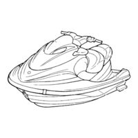
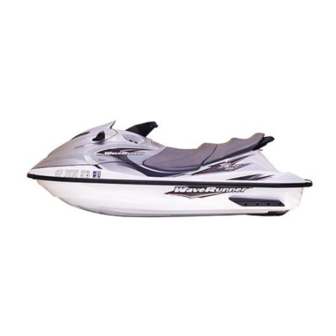
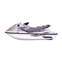
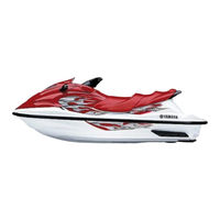
Sign In
Upload
Manuals
Brands
Yamaha Manuals
Boat
XLT1200 WaveRunner 2003
Yamaha XLT1200 WaveRunner 2003 Manuals
Manuals and User Guides for Yamaha XLT1200 WaveRunner 2003. We have
8
Yamaha XLT1200 WaveRunner 2003 manuals available for free PDF download: Service Manual, Owner's/Operator's Manual, Assembly Manual
Yamaha XLT1200 WaveRunner 2003 Service Manual (532 pages)
Brand:
Yamaha
| Category:
Boat
| Size: 15.28 MB
Table of Contents
How to Use this Manual
4
Important Information
6
Index
12
Table of Contents
13
General Information
14
Generales
15
Allgemeine
15
Chapter 1
16
Engine Serial Number
16
HULL IDENTIFICATION NUMBER (H.l.n.)
16
Identification Numbers
16
Jet Pump Unit Serial Number
16
Primary L.D. Number
16
Fire Prevention
18
Oils, Greases and Sealing Fluids
18
Safety While Working
18
Self-Protection
18
Ventilation
18
Good Working Practices
20
Disassembly and Assembly
22
Special Tools
24
Measuring
24
Removal and Installation
26
Specifications
28
Chapter 2
30
General Specifications
30
Maintenance Specifications
38
Maintenance Specifications
44
Engine
46
Specified Torques
46
Hull and Hood
48
Jet Pump Unit
48
General Torque
52
Cable and Hose Routing
54
Tightening Torques
46
Periodic Inspection and Adjustment
58
Inspection
59
Periodique Et
59
Reglage
59
Chapter 3
60
Maintenance Interval Chart
60
Control System
64
Periodic Service
64
Steering Master Inspection
64
Steering Cable Inspection and Adjustment
64
Throttle Cable Inspection and Adjustment
66
Choke Cable Inspection and Adjustment
68
QSTS Cable Inspection and Adjustment
68
Shift Cable Inspection and Adjustment
72
YPVS Cable Adjustment
74
Fuel System
76
Fuel Line Inspection
76
Trolling Speed Check and Adjustment
78
Kraftstoffanlage
79
Oil Injection System
80
Power Unit
80
Oil Line Inspection
80
Spark Plug Inspection
80
Electrical
82
Battery Inspection
82
Jet Pump Unit
88
Impeller Inspection
88
General
90
Water Inlet Strainer Inspection
90
Drain Plug Inspection
90
Lubrication Points
92
Recommended Lubricant
92
Recommended Grease
94
D'alimentation
99
Fuel Cock and Fuel Filter Exploded Diagram
102
Fuel Cock and Fuel Filter Removal and Installation Chart
102
CHAPTER 4 Service Points
104
Fuel Cock Inspection
104
Fuel Filter Inspection
104
Choke Cable Exploded Diagram
106
Choke Cable Removal and Installation Chart
106
Oil Tank Exploded Diagram
108
Oil Tank Removal and Installation Chart
108
Oil Level Sensor Inspection
112
Oil Tank Inspection
112
Service Points
112
Fuel Tank Exploded Diagram
114
Fuel Tank Removal and Installation Chart
114
Check Valve Inspection
120
Fuel Level Sensor Inspection
120
Fuel Tank Inspection
120
Service Points
120
Intake Duct and Silencer Exploded Diagram
122
Intake Duct and Silencer Removal and Installation Chart
122
Carburetor Unit Exploded Diagram
126
Carburetor Unit Removal and Installation Chart
126
Service Points
134
Throttle Valve Synchronization Inspection and Adjustment
134
Choke Valve Synchronization Inspection and Adjustment
136
Carburetor Assembly
138
Choke Cable and Throttle Cable Installation
138
Oil Pump Cable Installation
138
Carburetor Exploded Diagram
140
Carburetor Removal and Installation Chart
140
Accelerator Pump Body Inspection
146
Arm Inspection
146
Carburetor Service Points
146
Diaphragm Inspection
146
Needle Valve Inspection
148
Regulator Body Inspection
148
Carburetor Assembly
150
Jet and Carburetor Body Inspection
150
Fuel Pump Exploded Diagram
152
Fuel Pump Removal and Installation Chart
152
Fuel Pump Inspection
156
Service Points
156
Oil Pump Exploded Diagram
158
Oil Pump Removal and Installation Chart
158
Check Valve Inspection
164
Oil Hose Inspection
164
Oil Pump Inspection
164
Service Points
164
Oil Pump Cable Adjustment
166
Oil Injection Pump Air Bleeding
168
Air Bleed Screw
168
Recommended Engine Oil
168
Moteur
171
Exhaust Chamber Assembly Exploded Diagram
174
Exhaust Chamber Assembly Removal and Installation Chart
174
Muffler Assembly Exploded Diagram
182
Muffler Assembly Removal and Installation Chart
182
Catalyst Inspection
192
Exhaust Manifold and Leads Exploded Diagram
194
Exhaust Manifold and Leads Removal and Installation Chart
194
Engine Unit Exploded Diagram
202
Engine Unit Removal and Installation Chart
202
Coupling Clearance Inspection
206
Engine Mount Inspection
206
Shim Removal
206
Reed Valves Exploded Diagram
208
Reed Valves Removal and Installation Chart
208
Reed Valve Inspection
210
Ypvs Exploded Diagram
212
Ypvs Removal and Installation Chart
212
YPVS Valve Inspection
218
YPVS Valve Installation
218
Cylinder Head Exploded Diagram
220
Cylinder Head Removal and Installation Chart
220
Cylinder Head Inspection
224
Cylinders Exploded Diagram
226
Cylinders Removal and Installation Chart
226
Cylinder Inspection
228
Pistons Exploded Diagram
230
Pistons Removal and Installation Chart
230
Piston Inspection
234
Piston Pin Clip Removal and Installation
234
Cylinder and Piston Combination
236
Piston Ring Inspection
236
Piston Pin and Bearing Inspection
238
Generator and Starter Motor Exploded Diagram
242
Generator and Starter Motor Removal and Installation Chart
242
Drive Coupling Removal and Installation
254
Flywheel Magneto Removal and Installation
254
Drive Coupling Inspection
256
Flywheel Magneto Inspection
256
Starter Clutch Assembly Inspection
256
Crankcase Exploded Diagram
258
Crankcase Removal and Installation Chart
258
Crankcase Inspection
262
Crankcase Installation
262
Crankshaft Exploded Diagram
264
Crankshaft Removal and Installation Chart
264
Crankshaft Inspection
266
Jet Pump Unit Exploded Diagram
274
Jet Pump Unit Removal and Installation Chart
274
Pompe de Propulsion
275
Jet Pump
276
Reverse Gate Exploded Diagram
280
Reverse Gate Removal and Installation Chart
280
Lever 1 Installation
286
Lever 2 Installation
286
Jet Thrust Nozzle and Nozzle Ring Exploded Diagram
288
Jet Thrust Nozzle and Nozzle Ring Removal and Installation Chart
288
Impeller Duct, Impeller Housing, and Intake Duct Exploded Diagram
290
Impeller Duct, Impeller Housing, and Intake Duct Removal and Installation Chart
290
Impeller Duct and Drive Shaft Exploded Diagram
294
Impeller Duct and Drive Shaft Removal and Installation Chart
294
Drive Shaft Removal
298
Drive Shaft Inspection
300
Drive Shaft Installation
300
Transom Plate and Hoses Exploded Diagram
306
Transom Plate and Hoses Removal and Installation Chart
306
Bilge Hose Inspection
310
Bearing Housing Exploded Diagram
312
Bearing Housing Removal and Installation Chart
312
Bearing Removal
318
Driven Coupling Removal and Installation
318
Intermediate Drive Shaft Removal
318
Bearing Installation
320
Bearing, Intermediate Drive Shaft, and Grease Hose Inspection
320
Driven Coupling Inspection
320
Oil Seal Installation
322
Intermediate Housing Installation
324
Electrical System
326
Chapter 7
330
Electrical Components
330
Elektrische Anlage
331
Electrical Box Exploded Diagram
332
Electrical Box Removal and Installation Chart
332
Digital Tester
346
Electrical Analysis Inspection
346
Low Resistance Measurement
348
Peak Voltage Adaptor
348
Peak Voltage Measurement
348
Test Harness
350
Ignition System Wiring Diagram
352
Ignition Spark Gap
354
Ignition System Peak Voltage
356
Spark Plug Lead Assembly
360
Engine Stop Switch
362
Ignition Coil
362
Exhaust Temperature Sensor
364
Water Temperature Sensor
364
Starting System Wiring Diagram
366
Fuse
368
Start Switch
370
Starter Relay
370
Starting System Wiring Connections
368
Starter Motor Exploded Diagram
372
Starter Motor Removal and Installation Chart
372
Armature Inspection
378
Brush Holder Inspection
380
Starter Motor Front Cover Inspection
380
Charging System Wiring Diagram
382
YPVS Wiring Diagram
386
YPVS Servomotor Exploded Diagram
390
YPVS Servomotor Removal and Installation Chart
390
YPVS Cable Inspection
392
YPVS Cable Removal and Installation
392
YPVS Servomotor Inspection
392
Indication System Wiring Diagram
396
Buzzer
398
Oil Level Sensor
398
Fuel Level Sensor
400
Multifunction Meter
400
Display Function
404
Fuel Level Gauge
408
Oil Level Gauge
410
Overheat Warning Indicator
412
Speed Meter
418
Speed Sensor
420
Hull and Hood
422
Advertisement
Yamaha XLT1200 WaveRunner 2003 Owner's/Operator's Manual (142 pages)
Brand:
Yamaha
| Category:
Boat
| Size: 11.81 MB
Table of Contents
General and Safety 1
5
Table of Contents
5
Features and Functions
5
Maintenance and Care
5
Identification Numbers
8
Primary Identification (PRI-ID) Number
8
Hull Identification Number (HIN)
8
Engine Serial Number
8
Emission Control Information
9
Approval Label of Emission Control Certificate
9
Manufactured Date Label
9
Important Labels
10
Label Location
10
Warning Labels
11
Caution Labels
13
Other Labels
14
Safety Information
15
Limitations on Who May Operate the Watercraft
15
Cruising Limitations
16
Operation Requirements
17
Recommended Equipment
19
Hazard Information
20
Watercraft Characteristics
20
Water-Skiing
21
Give-Way Vessel
23
Rules When Encountering Vessels
24
Other Special Situations
25
Reading Buoys and Other Markers
25
Rules of the Road
23
Steering and Sailing Rules
23
Stand-On Vessel
23
Fishing Vessel Right-Of-Way
25
Narrow Channels and Bends
25
Sailing Vessel Right-Of-Way
25
To Get more Boating Safety Information
27
United States Coast Guard
27
Other Sources
27
Watercraft Education and Training
27
Enjoy Your Watercraft Responsibly
28
Features and Functions
29
Operation
29
Location of Main Components
30
Operation of Controls and Other Functions
34
Rear Seat
34
Front Seat
35
Hood
36
Fuel Tank Filler Cap
37
Oil Tank Filler Cap
37
Fuel Cock Knob
38
Engine Stop Switch
39
Engine Shut-Off Switch
39
Choke Knob
39
Throttle Lever
40
Start Switch
40
Cooling Water Pilot Outlet
41
Steering System
41
Tilt Lever
42
Shift Lever
43
Quick Shift Trim System (QSTS) Selector
44
Handgrip
45
Bow down
45
Bow up
45
Engine Overheat Warning System
46
Exhaust Temperature Warning System
48
Multifunction Meter
49
PADLOC (Programmable Digital Locking Ignition)
50
Selecting "Padloc" Mode
51
Tachometer
52
Speedometer
53
Fuel Meter
53
Engine Oil Meter
54
Clock
54
Hour Meter
55
Trip Timer
55
Tripmeter
56
Fuel Warning Indicator
56
Oil Warning Indicator
57
Engine Overheat Warning Indicator
57
Exhaust Temperature Warning Indicator
58
Battery Warning Indicator
58
Storage Compartments
59
Front Storage Compartment
59
Glove Compartment
60
Seat Storage Compartment
60
Operation
61
Fuel and Oil
62
Gasoline
62
2-Stroke Engine Oil
63
Filling the Fuel Tank
64
Filling the Oil Tank
65
Pre-Operation Checks
66
Pre-Operation Check List
66
Pre-Operation Check Points
67
Engine Compartment
67
Fuel and Oil Systems
67
Water Separator
68
Fire Extinguisher
70
Shift Lever and Reverse Gate
72
Engine Shut-Off Cord (Lanyard)
73
Jet Unit
73
Operation
75
Engine Break-In
75
Launching the Watercraft
77
Starting the Engine
77
Stopping the Engine
80
Leaving the Watercraft
80
Operating Your Watercraft
81
Getting to Know Your Watercraft
81
Learning to Operate Your Watercraft
81
Riding Watercraft with Passengers
82
Starting the Watercraft
83
Starting from a Dock
84
Boarding and Starting in Deep Water
85
Boarding Alone
85
Boarding with Passengers
86
Capsized Watercraft
87
Turning the Watercraft
89
Stopping the Watercraft
91
Beaching the Watercraft
92
Docking the Watercraft
92
Reverse on Waterways
93
Rough Water Operation
93
Post-Operation Checks
94
Transporting
96
Yamaha XLT1200 WaveRunner 2003 Owner's/Operator's Manual (138 pages)
Brand:
Yamaha
| Category:
Boat
| Size: 11.51 MB
Table of Contents
General and Safety 1
4
Table of Contents
4
Features and Functions
4
Maintenance and Care
4
Identification Numbers
6
Primary Identification (PRI-ID) Number
6
Hull Identification Number (HIN)
6
Engine Serial Number
6
Emission Control Information
7
Approval Label of Emission Control Certificate
7
Manufactured Date Label
7
Important Labels
8
Label Location
8
Warning Labels
9
Other Labels
10
Safety Information
12
Limitations on Who May Operate the Watercraft
12
Cruising Limitations
13
Operation Requirements
14
Recommended Equipment
16
Hazard Information
17
Watercraft Characteristics
17
Water-Skiing
18
Rules of the Road
20
Steering and Sailing Rules
20
Stand-On Vessel
20
Give-Way Vessel
20
Rules When Encountering Vessels
21
Other Special Situations
22
Reading Buoys and Other Markers
22
Sailing Vessel Right-Of-Way
22
Narrow Channels and Bends
22
Fishing Vessel Right-Of-Way
22
To Get more Boating Safety Information
24
United States Coast Guard
24
Other Sources
24
Watercraft Education and Training
24
Enjoy Your Watercraft Responsibly
25
Features and Functions
27
Operation
27
Location of Main Components
28
Operation of Controls and Other Functions
32
Rear Seat
32
Front Seat
33
Hood
34
Fuel Tank Filler Cap
35
Oil Tank Filler Cap
35
Fuel Cock Knob
36
Engine Stop Switch
37
Engine Shut-Off Switch
37
Choke Knob
37
Throttle Lever
38
Start Switch
38
Cooling Water Pilot Outlet
39
Steering System
39
Tilt Lever
40
Shift Lever
41
Quick Shift Trim System (QSTS) Selector
42
Handgrip
43
Bow down
43
Bow up
43
Engine Overheat Warning System
44
Exhaust Temperature Warning System
46
Multifunction Meter
47
PADLOC (Programmable Digital Locking Ignition)
48
Selecting "Padloc" Mode
49
Tachometer
50
Speedometer
51
Fuel Meter
51
Engine Oil Meter
52
Clock
52
Hour Meter
53
Trip Timer
53
Tripmeter
54
Fuel Warning Indicator
54
Oil Warning Indicator
55
Engine Overheat Warning Indicator
55
Exhaust Temperature Warning Indicator
56
Battery Warning Indicator
56
Storage Compartments
57
Front Storage Compartment
57
Glove Compartment
58
Seat Storage Compartment
58
Operation
59
Fuel and Oil
60
Gasoline
60
2-Stroke Engine Oil
62
Filling the Fuel Tank
62
Filling the Oil Tank
63
Pre-Operation Checks
64
Pre-Operation Check List
64
Pre-Operation Check Points
65
Engine Compartment
65
Hull and Deck
65
Fuel and Oil Systems
66
Water Separator
66
Stern Drain Plug
67
Fire Extinguisher
69
Shift Lever and Reverse Gate
71
Quick Shift Trim System (Qsts)
72
Jet Unit
73
Engine Shut-Off Cord (Lanyard)
73
Operation
75
Engine Break-In
75
Launching the Watercraft
77
Starting the Engine
77
Stopping the Engine
80
Leaving the Watercraft
80
Operating Your Watercraft
81
Getting to Know Your Watercraft
81
Learning to Operate Your Watercraft
81
Riding Watercraft with Passengers
82
Starting the Watercraft
83
Water
84
Boarding and Starting in Deep
85
Boarding Alone
85
Boarding with Passengers
86
Capsized Watercraft
87
Turning the Watercraft
89
Stopping the Watercraft
91
Beaching the Watercraft
92
Docking the Watercraft
92
Reverse on Waterways
93
Rough Water Operation
93
Post-Operation Checks
94
Transporting
96
Advertisement
Yamaha XLT1200 WaveRunner 2003 Owner's/Operator's Manual (138 pages)
Brand:
Yamaha
| Category:
Boat
| Size: 11.45 MB
Table of Contents
General and Safety 1
4
Table of Contents
4
Features and Functions
4
Maintenance and Care
4
Identification Numbers
6
Primary Identification (PRI-ID) Number
6
Hull Identification Number (HIN)
6
Engine Serial Number
7
Emission Control Information
8
Approval Label of Emission Control Certificate
8
Manufactured Date Label
8
Important Labels
9
Label Location
9
Warning Labels
10
Other Labels
11
Safety Information
13
Limitations on Who May Operate the Watercraft
13
Cruising Limitations
14
Operation Requirements
15
Recommended Equipment
17
Hazard Information
18
Watercraft Characteristics
18
Water-Skiing
19
Rules of the Road
21
Steering and Sailing Rules
21
Stand-On Vessel
21
Give-Way Vessel
21
Rules When Encountering Vessels
22
Other Special Situations
23
Reading Buoys and Other Markers
23
Sailing Vessel Right-Of-Way
23
Narrow Channels and Bends
23
Fishing Vessel Right-Of-Way
23
To Get more Boating Safety Information
25
United States Coast Guard
25
Other Sources
25
Watercraft Education and Training
25
Enjoy Your Watercraft Responsibly
26
Features and Functions
27
Operation
27
Location of Main Components
28
Operation of Controls and Other Functions
32
Rear Seat
32
Front Seat
33
Hood
34
Fuel Tank Filler Cap
35
Oil Tank Filler Cap
35
Fuel Cock Knob
36
Engine Stop Switch
37
Engine Shut-Off Switch
37
Choke Knob
37
Throttle Lever
38
Start Switch
38
Cooling Water Pilot Outlet
39
Steering System
39
Tilt Lever
40
Shift Lever
41
Quick Shift Trim System (QSTS) Selector
42
Handgrip
43
Bow down
43
Bow up
43
Engine Overheat Warning System
44
Exhaust Temperature Warning System
46
Multifunction Meter
47
PADLOC (Programmable Digital Locking Ignition)
48
Selecting "Padloc" Mode
49
Tachometer
50
Speedometer
51
Fuel Meter
51
Engine Oil Meter
52
Clock
52
Hour Meter
53
Trip Timer
53
Tripmeter
54
Fuel Warning Indicator
54
Oil Warning Indicator
55
Engine Overheat Warning Indicator
55
Exhaust Temperature Warning Indicator
56
Battery Warning Indicator
56
Storage Compartments
57
Front Storage Compartment
57
Glove Compartment
58
Seat Storage Compartment
58
Operation
59
Fuel and Oil
60
Gasoline
60
2-Stroke Engine Oil
62
Filling the Fuel Tank
62
Filling the Oil Tank
63
Pre-Operation Checks
64
Pre-Operation Check List
64
Pre-Operation Check Points
65
Engine Compartment
65
Fuel and Oil Systems
65
Water Separator
66
Fire Extinguisher
68
Shift Lever and Reverse Gate
70
Jet Unit
71
Engine Shut-Off Cord (Lanyard)
71
Operation
73
Engine Break-In
73
Launching the Watercraft
75
Starting the Engine
75
Stopping the Engine
78
Leaving the Watercraft
78
Operating Your Watercraft
79
Getting to Know Your Watercraft
79
Learning to Operate Your Watercraft
79
Riding Watercraft with Passengers
80
Starting the Watercraft
81
Water
82
Starting from a Dock
82
Boarding and Starting in Deep
83
Boarding Alone
83
Boarding with Passengers
84
Capsized Watercraft
85
Turning the Watercraft
87
Stopping the Watercraft
89
Beaching the Watercraft
90
Docking the Watercraft
90
Reverse on Waterways
91
Rough Water Operation
91
Post-Operation Checks
92
Transporting
94
Yamaha XLT1200 WaveRunner 2003 Owner's/Operator's Manual (138 pages)
Brand:
Yamaha
| Category:
Boat
| Size: 3.3 MB
Table of Contents
General and Safety 1
4
Table of Contents
4
Features and Functions
4
Maintenance and Care
4
Troubleshooting and Emergency Procedures
4
Emission Control Information
6
Approval Label of Emission Control
6
Manufactured Date Label
6
Important Labels
7
Label Location
7
Warning Labels
8
Caution Labels
10
Other Labels
11
Safety Information
12
Limitations on Who May Operate the
12
Cruising Limitations
13
Identification Numbers
14
Hull Identification Number
14
Engine Serial Number
14
Primary Identification (Pri-ID) Number
14
Operation Requirements
15
Hazard Information
18
Watercraft Characteristics
18
Water-Skiing
19
Rules of the Road
21
Steering and Sailing Rules
21
Stand-On Vessel
21
Give-Way Vessel
21
Rules When Encountering Vessels
22
Other Special Situations
23
Reading Buoys and Other Markers
23
Sailing Vessel Right-Of-Way
23
Narrow Channels and Bends
23
Fishing Vessel Right-Of-Way
23
To Get more Boating Safety Information
25
United States Coast Guard
25
Other Sources
25
Watercraft Education and Training
25
Enjoy Your Watercraft Responsibly
26
Features and Functions
27
Operation
27
Location of Main Components
28
Operation of Controls and Other Functions
32
Rear Seat
32
Front Seat
33
Hood
34
Fuel Tank Filler Cap
35
Oil Tank Filler Cap
35
Fuel Cock Knob
36
Engine Stop Switch
37
Engine Shut-Off Switch
37
Choke Knob
37
Throttle Lever
38
Start Switch
38
Cooling Water Pilot Outlet
39
Steering System
39
Tilt Lever
40
Shift Lever
41
Quick Shift Trim System (QSTS) Selector
42
Bow down
43
Bow up
43
Engine Overheat Warning System
44
Exhaust Temperature Warning System
46
Handgrip
47
Multifunction Meter
48
PADLOC (Programmable Digital Locking Ignition)
49
Selecting "Padloc" Mode
50
Tachometer
51
Speedometer
52
Fuel Meter
52
Engine Oil Meter
53
Clock
53
Hour Meter
54
Trip Timer
54
Tripmeter
55
Fuel Warning Indicator
55
Oil Warning Indicator
56
Engine Overheat Warning Indicator
56
Exhaust Temperature Warning Indicator
57
Battery Warning Indicator
57
Storage Compartments
58
Front Storage Compartment
58
Glove Compartment
59
Seat Storage Compartment
59
Operation
61
Fuel and Oil
62
Gasoline
62
Filling the Fuel Tank
64
2-Stroke Engine Oil
64
Filling the Oil Tank
65
Pre-Operation Checks
66
Pre-Operation Check List
66
Pre-Operation Check Points
67
Engine Compartment
67
Fuel and Oil Systems
67
Water Separator
68
Fire Extinguisher
70
Shift Lever and Reverse Gate
72
Jet Unit
73
Engine Shut-Off Cord (Lanyard)
73
Operation
75
Engine Break-In
75
Launching the Watercraft
77
Starting the Engine
77
Stopping the Engine
80
Leaving the Watercraft
80
Operating Your Watercraft
81
Getting to Know Your Watercraft
81
Learning to Operate Your Watercraft
81
Riding Watercraft with Passengers
82
Starting the Watercraft
83
Starting from a Dock
84
Boarding and Starting in Deep Water
85
Boarding Alone
85
Boarding with Passengers
86
Capsized Watercraft
87
Turning the Watercraft
89
Stopping the Watercraft
91
Beaching the Watercraft
92
Docking the Watercraft
92
Reverse on Waterways
93
Rough Water Operation
93
Post-Operation Checks
94
Transporting
96
Yamaha XLT1200 WaveRunner 2003 Owner's/Operator's Manual (136 pages)
Brand:
Yamaha
| Category:
Boat
| Size: 9.16 MB
Table of Contents
General and Safety 1
4
Table of Contents
4
Features and Functions
4
Maintenance and Care
4
Identification Numbers
6
Primary Identification (PRI-ID) Number
6
Hull Identification Number (HIN)
6
Engine Serial Number
6
Emission Control Information
7
Approval Label of Emission Control Certificate
7
Manufactured Date Label
7
Important Labels
8
Label Location
8
Warning Labels
9
Other Labels
10
Safety Information
12
Limitations on Who May Operate the Watercraft
12
Cruising Limitations
13
Operation Requirements
14
Recommended Equipment
16
Hazard Information
17
Watercraft Characteristics
17
Water-Skiing
18
Rules of the Road
20
Steering and Sailing Rules
20
Stand-On Vessel
20
Give-Way Vessel
20
Rules When Encountering Vessels
21
Other Special Situations
22
Reading Buoys and Other Markers
22
Sailing Vessel Right-Of-Way
22
Narrow Channels and Bends
22
Fishing Vessel Right-Of-Way
22
To Get more Boating Safety Information
24
United States Coast Guard
24
Other Sources
24
Watercraft Education and Training
24
Enjoy Your Watercraft Responsibly
25
Features and Functions
26
Operation
26
Location of Main Components
27
Operation of Controls and Other Functions
31
Rear Seat
31
Front Seat
32
Hood
33
Fuel Tank Filler Cap
34
Oil Tank Filler Cap
34
Fuel Cock Knob
35
Engine Stop Switch
36
Engine Shut-Off Switch
36
Choke Knob
36
Throttle Lever
37
Start Switch
37
Cooling Water Pilot Outlet
38
Steering System
38
Tilt Lever
39
Shift Lever
40
Quick Shift Trim System (QSTS) Selector
41
Handgrip
42
Bow down
42
Bow up
42
Engine Overheat Warning System
43
Exhaust Temperature Warning System
45
Multifunction Meter
46
PADLOC (Programmable Digital Locking Ignition)
47
Selecting "Padloc" Mode
48
Tachometer
49
Speedometer
50
Fuel Meter
50
Engine Oil Meter
51
Clock
51
Hour Meter
52
Trip Timer
52
Tripmeter
53
Fuel Warning Indicator
53
Oil Warning Indicator
54
Engine Overheat Warning Indicator
54
Exhaust Temperature Warning Indicator
55
Battery Warning Indicator
55
Storage Compartments
56
Front Storage Compartment
56
Glove Compartment
57
Seat Storage Compartment
57
Operation
58
Fuel and Oil
59
Gasoline
59
2-Stroke Engine Oil
61
Filling the Fuel Tank
61
Filling the Oil Tank
62
Pre-Operation Checks
63
Pre-Operation Check List
63
Pre-Operation Check Points
64
Engine Compartment
64
Hull and Deck
64
Fuel and Oil Systems
65
Water Separator
65
Stern Drain Plug
66
Fire Extinguisher
68
Shift Lever and Reverse Gate
70
Quick Shift Trim System (Qsts)
71
Jet Unit
72
Engine Shut-Off Cord (Lanyard)
72
Operation
74
Engine Break-In
74
Launching the Watercraft
76
Starting the Engine
76
Stopping the Engine
79
Leaving the Watercraft
79
Operating Your Watercraft
80
Getting to Know Your Watercraft
80
Learning to Operate Your Watercraft
80
Riding Watercraft with Passengers
81
Starting the Watercraft
82
Water
83
Boarding and Starting in Deep
84
Boarding Alone
84
Boarding with Passengers
85
Capsized Watercraft
86
Turning the Watercraft
88
Stopping the Watercraft
90
Beaching the Watercraft
91
Docking the Watercraft
91
Reverse on Waterways
92
Rough Water Operation
92
Post-Operation Checks
93
Transporting
95
Yamaha XLT1200 WaveRunner 2003 Service Manual (57 pages)
Brand:
Yamaha
| Category:
Boat
| Size: 3.7 MB
Table of Contents
Table of Contents
8
Exhaust Chamber Assembly
10
Exploded Diagram
10
Removal and Installation Chart
10
Muffler Assembly
14
Exploded Diagram
15
Removal and Installation Chart
17
Service Point
19
Catalyst Inspection
19
Exhaust Manifold and Leads
20
Exploded Diagram
20
Removal and Installation Chart
20
Engine Unit
24
Exploded Diagram
24
Removal and Installation Chart
24
Service Points
26
Shim Removal
26
Engine Mount Inspection
26
Coupling Clearance Inspection
26
Reed Valves
27
Exploded Diagram
27
Removal and Installation Chart
27
Service Points
28
Reed Valve Inspection
28
Ypvs
29
Exploded Diagram
29
Removal and Installation Chart
29
Service Points
32
YPVS Valve Inspection
32
YPVS Valve Installation
32
Cylinder Head
33
Exploded Diagram
33
Removal and Installation Chart
33
Service Points
35
Cylinder Head Inspection
35
Cylinders
36
Exploded Diagram
36
Removal and Installation Chart
36
Service Points
37
Cylinder Inspection
37
Pistons
38
Exploded Diagram
38
Removal and Installation Chart
38
Service Points
40
Piston Pin Clip Removal and Installation
40
Piston Inspection
40
Cylinder and Piston Combination
41
Piston Ring Inspection
41
Piston Pin and Bearing Inspection
42
Generator and Starter Motor
44
Exploded Diagram
44
Removal and Installation Chart
44
Service Points
50
Drive Coupling Removal and Installation
50
Flywheel Magneto Removal and Installation
50
Drive Coupling Inspection
51
Flywheel Magneto Inspection
51
Starter Clutch Assembly Inspection
51
Yamaha XLT1200 WaveRunner 2003 Assembly Manual (60 pages)
WaveRunner
Brand:
Yamaha
| Category:
Boat
| Size: 3.02 MB
Advertisement
Related Products
Yamaha XLT1200 WaveRunner 2002
Yamaha XLT1200 WaveRunner 2004
Yamaha XLT1200 WaveRunner 2005
Yamaha XLT800 WaveRunner 2004
Yamaha XLT800 WaveRunner 2003
Yamaha XLT800 WaveRunner 2002
Yamaha WaveRunner XLT1200 2001
Yamaha XL700 WaveRunner 2003
Yamaha XL700 WaveRunner 2004
Yamaha WaveRunner XL XL760W
Yamaha Categories
Motorcycle
Musical Instrument
Electronic Keyboard
Receiver
Amplifier
More Yamaha Manuals
Login
Sign In
OR
Sign in with Facebook
Sign in with Google
Upload manual
Upload from disk
Upload from URL