Sign In
Upload
Manuals
Brands
Wieland Manuals
Gateway
samos PRO COMPACT
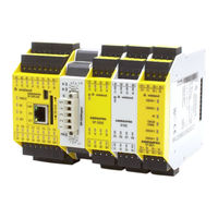
Wieland samos PRO COMPACT Controller Manuals
Manuals and User Guides for Wieland samos PRO COMPACT Controller. We have
2
Wieland samos PRO COMPACT Controller manuals available for free PDF download: Manual
Wieland samos PRO COMPACT Manual (200 pages)
Brand:
Wieland
| Category:
Gateway
| Size: 4 MB
Table of Contents
Table of Contents
3
Data Set
3
Instance
3
Instance
4
Instance
5
Instance
6
1 About this Manual
8
Function of this Document
8
Scope of Validity and Applicable Documents
9
Target Audience
9
Information Depth
10
Abbreviations and Definitions
11
Symbols/Icons and Writing Style/Spelling Standard Used
14
2 Safety
15
Qualified Persons
15
Proper Use
15
Environmentally Friendly Behavior
16
Disposal
16
Sorting of Materials
16
3 Product Description
17
Version, Compatibility, and Features
17
Equipment Variants
18
Data Transferred to the Network (Network Input Data Sets)
19
Direct Gateway Output Values
22
Module State / Input and Output Values
22
Transmission of Data from a Second Network
23
Configuration Test Values (Crcs)
23
Error and State Information for the Modules
23
Data Received from the Network (Network Output Data Sets)
27
4 Installation and Basic Configuration
28
Installing/Removing
28
Installing Modules on Standard Rail
28
Removing Modules from Normal Rail
31
Electrical Installation
33
Initial Configuration Steps
34
5 Configuration of Gateways
35
The Graphic User Interface ('Gateway' View)
35
When the "Gateway" View Is Active
35
Work Area
37
Sidebars
39
Commands
41
Function and Basic Settings
42
Routing
42
Basic Settings for the Operating Data
42
Configuring the Gateway Output Values (Tab 1)
44
Editing the Gateway Input Values (Tab 2)
46
Monitoring Operating Data
48
6 Modbus TCP Gateway
49
Interfaces and Operation
49
Basic Configuration - Allocation of an IP Address
50
Configuration of the Modbus-TCP Interface to the PLC - How the
52
Data Are Transferred
52
Diagnosis and Troubleshooting
59
State Bits
61
7 PROFINET IO-Gateway
62
Interfaces and Operation
62
Basic Configuration - Assigning a Device Name and an IP Address
63
PROFINET Configuration of the Gateway - How the Data Are Trans
65
PROFINET Configuration of the Gateway - Which Data Are Transfer
68
Diagnostics and Troubleshooting
73
Deactivation of the PROFINET IO Function
75
State Bits
75
8 Ethernet/Ip Gateway
76
Interfaces and Operation
76
Datasheet
76
Basic Setup
77
Basic Configuration of PLC
77
Basic Configuration of the Controller Module
81
Configuring the Data to PLC
82
Configuring the Usage of Data from PLC
83
Supported CIP Objects
84
Identity Object
84
Assembly Object
85
Discrete Input Point Object
86
Discrete Output Point Object
88
Discrete Input Group Object
89
Discrete Output Group Object
90
PCCC Object
91
PCCC Telegram Structure
91
Word Range Write
92
Word Range Read
92
Typed Write
93
Typed Read
93
Protected Typed Logical Read with 2 Address Fields
95
Protected Typed Logical Write with 2 Address Fields
95
Protected Typed Logical Read with 3 Address Fields
96
Protected Typed Logical Write with 3 Address Fields
96
Vendor Object
97
Instance 1
97
Instance 6
98
Supported Assembly Data
101
List of Assembly Data
101
Assembly Instances for Logic Output Bytes
103
Assembly Instance 37 = 0X25
103
Assembly Instances 138 = 0X8A to 141 = 0X8D
103
Assembly Instances for Logic Input Bytes
104
Assembly Instance 57 = 0X39
104
Assembly Instances 167 = 0Xa7
104
Accessing to CIP Objects
106
Explicit Messaging
106
Implicit Messaging
106
Symbolic Addressing
107
Adjust Performance
108
Connection with more than One PLC
108
Diagnostics and Troubleshooting
109
Notifications Via Network
109
Explicit Message Connection
109
Implicit Message Connection
109
LED States
109
MS (Module Status)
109
NET (Network Status)
110
Link
111
ACT (Activity Status)
111
Diagnostic Functions in the Configuration Software
112
State Bits
113
9 PROFIBUS DP Gateway
114
Interfaces and Operation
114
Projecting
118
PROFIBUS Configuration of the Gateway - How the Data Are Trans
121
Diagnosis and Troubleshooting
127
10 Canopen Gateway
129
Interfaces and Operation
129
Canopen Configuration of the Gateway - How the Data Are Transfer
134
Canopen Configuration of the Gateway - Which Data Are Transferred
137
NMT - Network Management
138
Sync
139
Emergency
140
Node Guarding
144
PDO Communication
145
SDO Communication
147
SDO Object Directory
149
Guarding Protocols
155
Error Objects
157
Canopen Diagnostic Examples
160
Diagnosis and Troubleshooting
163
11 Ethercat Gateway
166
Interfaces and Operation
167
Ethercat Basics
170
Ethercat State Machine
172
Bus Topology and Cabling
174
Data Transferred into the Network
175
Data Set 1
176
Data Set 2
180
Data Set 3
181
Data Received from the Network
183
Configuring an Ethercat Network
185
Ethercat Configuration of the Gateway - How the Data Are Transfer
186
Diagnostic Leds on the Gateway and Troubleshooting
189
12 Technical Data
192
Modbus TCP, PROFINET IO and Ethernet/Ip Gateway
192
Ethercat Gateway
192
Profibus Dp
192
Canopen Gateways
193
Technical Data for Supply Circuit
193
General Technical Data
194
Dimensional Drawings
195
Controller Module
195
Canopen and PROFIBUS Gateways
196
Ethercat Gateway
197
13 Order Data
198
Hardware Modules and Accessories
198
Modules for Contact Expansion
200
Advertisement
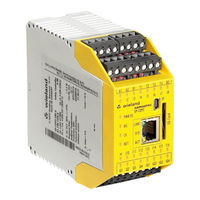
Wieland samos PRO COMPACT Manual (124 pages)
Brand:
Wieland
| Category:
Controller
| Size: 3 MB
Table of Contents
Table of Contents
3
1 About this Manual
7
Function of this Document
7
Target Group
7
Information Depth
8
Scope of Validity and Applicable Documents
8
Abbreviations Used
9
Symbols/Icons and Writing Style/Spelling Standard Used
10
2 Safety
11
Qualified Persons
11
Areas of Application of the Device
11
Proper Use
12
General Safety Information and Protective Measures
13
Environmentally Friendly Behavior
14
Disposal
14
Sorting of Materials
14
3 Product Description
15
System Properties
15
System Setup
16
Version, Compatibility, and Features
18
Controller Module SP-COP1
19
Description
19
Display Elements, Interfaces, and Terminal Description
19
Internal Circuits
22
Limited Short-Circuit Detection in the Input Circuits
22
Deactivating the Test Pulses at the Outputs
23
Single-Channel Use of Outputs
23
Controller Module SP-COP2-EN
24
Description
24
Display Elements, Interfaces, and Terminal Description
24
Internal Circuits
26
Limited Short-Circuit Detection in the Input Circuits
26
Deactivating the Test Pulses at the Outputs
27
Single-Channel Use of Outputs
27
Controller Module SP-COP2-ENI
28
Description
28
Display Elements, Error Codes, and Terminal Description
28
SP-COP-CARD1 Removable Storage
29
Description
29
Files on the Removable Storage
30
SP-SDIO Input/Output Expansion Module
32
Description
32
Display Elements and Terminal Assignment
33
Internal Circuits
34
Deactivating the Test Pulses at the Outputs
35
Single-Channel Use of Outputs
35
SP-SDI Input/Output Expansion Module
36
Description
36
Display Elements and Terminal Assignment
37
Internal Circuits
38
SP-DIO Input/Output Expansion Module
39
Description
39
Display Elements and Terminal Assignment
40
Internal Circuits
41
4 Connecting Devices
43
Safety Command Devices and Electromechanical Safety Switches
45
Emergency Stop Button
45
Electromechanical Safety Switch Without Lock
45
Electromechanical Safety Switch with Lock
46
Enable Switch
47
Two-Hand Control
47
Type IIIA
47
Type IIIC
48
Safety Mats and Bumper
48
Connection of Multiple Safety Mats/Bumpers
50
Mode Selection Switch
50
Potential-Free Contacts
51
Contactless Safety Sensors
52
Magnetic Safety Switches
52
Magnetic Safety Switches with Equivalent Inputs
52
Magnetic Safety Switches with Complementary Inputs
52
Inductive Safety Switches
52
Transponder Switches
53
Testable Single-Beam Safety Light Barriers
54
Testable Type 2 Single-Beam Safety Light Barriers
54
Testable Type 4 Single-Beam Safety Light Barriers
54
Customer-Specific Testable Single-Beam Safety Light Barriers
55
Information on Installing Testable Single-Beam Safety Light Barriers
55
ESPE - Electro-Sensitive Protective Equipment
57
Motion Monitoring
57
Safety Outputs
58
5 Special Functions
59
Muting
59
6 Installing/Removing
60
Installing Modules on hat Rail
60
Removing Modules from the hat Rail
64
7 Electrical Installation
66
Requirements for Electrical Installation
66
Internal Wiring of the Supply Voltage
68
8 Configuration
69
9 Commissioning
70
Total Acceptance of the Application
70
Tests before Initial Commissioning
70
10 Diagnostics
71
What to Do in the Event of an Error
71
Error Statuses
71
Error Displays in the Status Leds, Error Messages, Troubleshooting
72
Device State and LED Displays in the Controller Modules
73
Device State and LED Displays in the Safe Input/Output Modules
75
Device State and LED Displays in the Standard Input/Output Modules
76
Support
78
Expanded Diagnostics
78
11 Maintenance
79
Regular Testing of the Safety Equipment by Qualified Persons
79
Replacing Devices
80
Safety Measures When Replacing Devices
80
12 Technical Data
81
System Response Times
81
Minimum Switch-Off Time
83
Response Time of the State Flag
83
Default Values for Non-Secure or Secure Data
83
Safety Technology Reference Values
84
Controller Modules Without I/O Expansion
84
Controller Modules with Safe I/O Expansions
85
Data Sheet
86
Controller Module
86
Safe Input/Output Expansion Module
90
Safe Input Expansion Module
93
Standard Input/Output Expansion Module
95
Dimensional Drawings
97
Controller Module
97
Input/Output Expansion Modules
98
WKFN 2.5 E/35 GO-URL Level Terminal
98
13 Order Data
99
Hardware Modules and Accessories
99
Modules for Contact Expansion
101
Other Safety-Related Products
101
14 Appendix
102
Declaration of Conformity
102
Checklist for Manufacturers
106
Complete List of Error Messages
107
Advertisement
Related Products
Wieland samos PRO
Wieland samos PRO SP-SDIO
Wieland samos PRO SP-SDI
Wieland samos PRO SP-DIO
Wieland samos PRO SA-OR
Wieland samos PRO SP-PROFIBUS-DP
Wieland samos PRO SP-CANopen
Wieland samos PRO SP-EN-ETC
Wieland samos
Wieland SA-IN-S1-K-A
Wieland Categories
Cables and connectors
Control Unit
Network Router
Switch
Controller
More Wieland Manuals
Login
Sign In
OR
Sign in with Facebook
Sign in with Google
Upload manual
Upload from disk
Upload from URL