Sign In
Upload
Manuals
Brands
VIA Technologies Manuals
Motherboard
VAB-630
VIA Technologies VAB-630 Manuals
Manuals and User Guides for VIA Technologies VAB-630. We have
4
VIA Technologies VAB-630 manuals available for free PDF download: User Manual, Quick Start Manual, Installation Manual
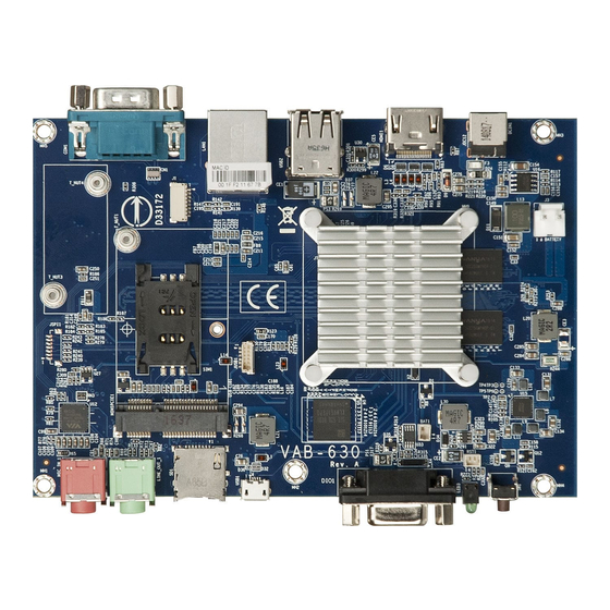
VIA Technologies VAB-630 User Manual (43 pages)
Cost effective single board computer with flexible I/O and rich connectivity
Brand:
VIA Technologies
| Category:
Motherboard
| Size: 2 MB
Table of Contents
Safety Precautions
3
Box Contents
4
Optional Accessories
4
Ordering Information
4
Table of Contents
5
1 Product Overview
10
Key Features
10
Product Specifications
11
Layout Diagram
13
Figure 1: Layout Diagram of the VAB-630 (Top View)
13
Figure 2: Layout Diagram of the VAB-630 (Bottom View)
13
Product Dimensions
14
Figure 3: Mounting Holes and Dimensions of the VAB-630 (Top View)
14
Figure 4: External I/O Port Dimensions of the VAB-630 (Front Panel)
14
Figure 5: External I/O Port Dimensions of the VAB-630 (Back Panel)
14
Height Distribution
15
Figure 6: Height Distribution of the VAB-630 (Top View)
15
Figure 7: Height Distribution of the VAB-630 (Bottom View)
15
2 I/O Interface
16
External I/O Ports
16
Figure 8: Front Panel I/O
16
Figure 9: Back Panel I/O
16
10/100Mbps Ethernet Port
17
Figure 10: Micro SD Card Slot Diagram
17
Figure 11: 10/100Mbps Ethernet Port Diagram
17
Micro SD Card Slot
17
Table 1: Micro SD Card Slot Pinouts
17
Table 2: 10/100Mpbs Ethernet Port Pinouts
17
Figure 12: USB 2.0 Port Diagram
18
Table 3: 10/100Mbps Ethernet Port LED Color Definition
18
Table 4: USB 2.0 Port Pinouts
18
USB 2.0 Port
18
Audio Jacks
19
Figure 13: Audio Jack Diagram
19
Figure 14: Micro USB 2.0 OTG Port Diagram
19
Micro USB 2.0 OTG Port
19
Table 5: Audio Jack Receptacle Description
19
Table 6: Micro USB 2.0 OTG Port Pinouts
19
DIO Port
20
Figure 15: DIO Port Diagram
20
Figure 16: Power LED Diagram
20
Power LED
20
Table 7: DIO Port Pinouts
20
DC-In Jack
21
Figure 17: Power Button Diagram
21
Figure 18: DC-In Jack Specification Diagram
21
Figure 19: DC-In Jack Diagram
21
Power Button
21
Table 10: DC-In Jack Pinouts
21
Table 8: Power Button Behavior Description
21
Table 9: DC-In Jack Specification
21
COM Port
22
Figure 20: COM Port Diagram
22
Figure 21: HDMI ® Port Diagram
22
HDMI ® Port
22
Table 11: COM Port Pinouts
22
Table 12: HDMI ® Port Pinouts
22
Onboard Connectors
23
SIM Card Slot
23
Figure 22: SIM Card Slot Diagram
23
Table 13 SIM Card Slot Pinouts
23
Minipcie Slot
24
Figure 23: Minipcie Slot Diagram
24
Table 14: Minipcie Slot Pinouts
24
C Touch Connector
25
Figure 24: I C Touch Connector Diagram
25
Table 15: I 2 C Touch Connector Pinouts
25
LVDS Panel Connector
26
Figure 25: LVDS Panel Connector Diagram
26
Table 16: LVDS Panel Connector Pinouts
26
Battery Connector
27
Reset Connector
27
Figure 26: Battery Connector Diagram
27
Figure 27: Reset Connector Diagram
27
Table 17: Battery Connector Pinouts
27
Table 18: Reset Connector Pinouts
27
RTC Battery Connector
28
UART Connector
28
Figure 28: RTC Battery Connector Diagram
28
Figure 29: UART Connector Diagram
28
Table 19: RTC Battery Connector Pinouts
28
Table 20: UART Connector Pinouts
28
USB 2.0 Connector
29
Figure 30: USB 2.0 Connector Diagram
29
Table 21: USB 2.0 Connector Pinouts
29
3 Hardware Installation
30
Installing into a Chassis
30
Suggested Minimum Chassis Dimensions
30
Suggested Minimum Chassis Height
30
Figure 31: Suggested Minimum Chassis Dimensions
30
Figure 32: Suggested Minimum Internal Ceiling Height
30
Suggested Keepout Areas
31
Figure 33: Suggested Keepout Top Areas
31
Figure 34: Suggested Keepout Bottom Areas
31
4 Software and Technical Supports
32
Android Support
32
Technical Supports and Assistance
32
Appendix A. Installing Wireless Accessories
33
Installing the EMIO-2550 Minipcie Mobile Broadband Module
33
Figure 35: Installing SIM Card
33
Figure 36: Inserting the EMIO-2550 Module
34
Figure 37: Securing the EMIO-2550 Module
34
Figure 38: Connecting the Antenna Cable and Antenna
35
Figure 39: Connecting the Antenna (to the Micro-RF Connector)
35
Installing the EMIO-2531 Minipcie Wi-Fi & Bluetooth Module
36
Figure 40: Inserting the EMIO-2531 Module
36
Figure 41: Securing the EMIO-2531 Module
36
Figure 42: Connecting the Wi-Fi Antenna Cable and Antenna
37
Figure 43: Connecting the Antenna Cable to the Micro-RF Connector
37
Installing EMIO-5531 USB Wi-Fi Module
38
Figure 44: Installing and Securing EMIO-5531 Module
38
Figure 45: Connecting USB Wi-Fi Cable
38
Figure 46: Connecting the Antenna Cable and Antenna
39
Figure 47: Connecting the Antenna Cable to the Micro-RF Connector
39
Appendix B. Installing LVDS Panel Display
40
Connecting the LVDS Panel Display to the VAB-630 Board
40
Figure 48: Connecting the Touch Screen Cable to the Touch Controller Module
40
Figure 49: Connecting the USB Touch Cable
40
Figure 50: Connecting the Flex Flat Cable
41
Table 22: VAB-630 Connector Vendor Lists
42
Advertisement
VIA Technologies VAB-630 Quick Start Manual (26 pages)
Android EVK v1.0.3
Brand:
VIA Technologies
| Category:
Motherboard
| Size: 3 MB
Table of Contents
Table of Contents
4
1 Introduction
5
EVK Package Contents
5
Firmware Folder Contents
5
Document Folder Contents
5
Tools Folder Contents
5
Version Information and Supported Features
6
2 Image Installation
7
Requirements
7
Booting from the SPI ROM with Emmc
7
3 Hardware Functions
8
Setting up U-Boot Parameters
8
Configuring Display Parameters
10
Setting up the LVDS Display Parameter
10
Setting up the HDMI Display Parameter
11
Smart ETK
12
Installing Smart ETK
12
Testing Watchdog Timer Function
13
Testing GPIO Function
14
Testing UART Function
16
4 Accessories
18
Configuring the EMIO-2531 Minipcie / EMIO-5531 USB Wi-Fi & Bluetooth Module
18
Connecting to the Internet
18
Enabling Bluetooth
20
Setting up Bluetooth A2DP Profile
20
Setting up Bluetooth SPP Profile
20
Configuring the EMIO-2550 Minipcie Mobile Broadband Module
23
Connecting to the Internet
23
Enabling 3G
24
VIA Technologies VAB-630 Quick Start Manual (23 pages)
Brand:
VIA Technologies
| Category:
Computer Hardware
| Size: 2 MB
Table of Contents
Table of Contents
4
Introduction
5
EVK Package Contents
5
Firmware Folder Contents
5
Document Folder Contents
5
Version Information and Supported Features
6
Image Installation
7
Requirements
7
Booting from the SPI ROM with Emmc
7
Hardware Functions
8
Setting up U-Boot Parameters
8
Configuring Display Parameters
10
Setting up the LVDS Display Parameter
10
Setting up the HDMI Display Parameter
11
Configuring Watchdog Timer
12
Setting up GPIO
13
Setting up DIO Port for GPIO Functionality
13
Setting up GPI Mode
14
Setting up GPO Mode
14
Configuring UART
15
Accessories
16
Configuring the EMIO-2531 Minipcie/Emio-5531 USB Wi-Fi & Bluetooth Module
16
Connecting to the Internet
16
Enabling Bluetooth
18
Setting up Bluetooth A2DP Profile
18
Setting up the Bluetooth SPP Profile
18
Configuring the EMIO-2550 Minipcie Mobile Broadband Module
20
Connecting to the Internet
20
Advertisement
VIA Technologies VAB-630 Installation Manual (8 pages)
Android EVK v1.0.2
Brand:
VIA Technologies
| Category:
Computer Hardware
| Size: 0 MB
Table of Contents
Table of Contents
4
Introduction
5
Package Contents
5
Version Information and Supported Features
6
Image Development
7
Booting from the SPI ROM an Emmc
7
Advertisement
Related Products
VIA Technologies VAB-800
VIA Technologies VAB-1000
VIA Technologies VAB-820
VIA Technologies VAB-950
VIA Technologies VB8001-16 - VIA Motherboard - Mini ITX
VIA Technologies VIA KT266A ChipsetMotherboard
VIA Technologies VIA EPIA
VIA Technologies VB9001
VIA Technologies VX900
VIA Technologies VT82C686A
VIA Technologies Categories
Motherboard
Computer Hardware
Desktop
Control Unit
Industrial PC
More VIA Technologies Manuals
Login
Sign In
OR
Sign in with Facebook
Sign in with Google
Upload manual
Upload from disk
Upload from URL