Sign In
Upload
Manuals
Brands
VIA Technologies Manuals
Motherboard
VAB-950
VIA Technologies VAB-950 Manuals
Manuals and User Guides for VIA Technologies VAB-950. We have
6
VIA Technologies VAB-950 manuals available for free PDF download: User Manual, Quick Start Manual, How To Connect
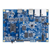
VIA Technologies VAB-950 User Manual (39 pages)
Fanless low-power platform for AIoT applications with octa-core MediaTek i500 processor
Brand:
VIA Technologies
| Category:
Motherboard
| Size: 2 MB
Table of Contents
Table of Contents
5
1 Product Overview
8
Key Features
8
Product Specifications
9
Layout Diagram
11
Figure 1: Layout Diagram of the VIA VAB-950 (Top Side)
11
Figure 2: Layout Diagram of the VIA VAB-950 Front Panel I/O
11
Figure 3: Layout Diagram of the VIA VAB-950 Back Panel I/O
11
Figure 4: Layout Diagram of the VIA VAB-950 Right Panel I/O
11
Product Dimensions
12
Figure 5: Dimensions of the VIA VAB-950 (Top View)
12
Figure 6: External I/O Dimensions of the VIA VAB-950 (Front Panel)
12
Figure 7: External I/O Dimensions of the VIA VAB-950 (Back Panel)
12
Figure 8: External I/O Dimensions of the VIA VAB-950 (Right Panel)
12
Height Distribution
13
Figure 9: Height Distribution Of The Via Vab-950 (Top Side)
13
2 External I/O Pin Descriptions And Functionality
14
HDMI® Port
14
USB 2.0 Port
14
Figure 10: HDMI Port Diagram
14
Figure 11: USB 2.0 Port Diagram
14
Table 1: HDMI Port Pinouts
14
Table 2: USB 2.0 Port Pinouts
14
10/100Mbps Ethernet Ports
15
Micro USB 2.0 Port
15
Figure 12: 10/100Mbps Ethernet Port Diagram
15
Figure 13: Micro USB 2.0 Port Diagram
15
Table 3: 10/100Mbps Ethernet Ports Pinouts
15
Table 4: 10/100Mbps Ethernet Port LED Color Definition
15
Table 5: Micro USB 2.0 Port Pinouts
15
Headphone Jack
16
Reset Button
16
Power Button
16
Figure 14: Headphone Jack Diagram
16
Figure 15: Reset Button Diagram
16
Figure 16: Power Button Diagram
16
Power Button Behavior Description
16
3 Onboard I/O
17
Minipcie Slot
17
Figure 17: Minipcie Slot Diagram
17
Table 7: Minipcie Slot Pinouts
17
SIM Card Slot
18
Figure 18: SIM Card Slot Diagram
18
Table 8: SIM Card Slot Pinouts
18
COM Connectors
19
Figure 19: COM Connectors Diagram
19
Table 9: COM Connectors Pinouts
19
Battery Charger Connector
20
DC-In Connector
20
Figure 20: Battery Charger Connector Diagram
20
Figure 21: DC-In Connector Diagram
20
Table 10: Battery Charger Connector Pinouts
20
Table 11: DC-In Connector Pinouts
20
MIPI CSI-2 Connector
21
Figure 22: MIPI CSI-2 Connector Diagram
21
Table 12: MIPI CSI-2 Connector Pinouts
21
MIPI DSI Connector
22
Figure 23: MIPI DSI Connector Diagram
22
Table 13: MIPI DSI Connector Pinouts
22
Touch Screen Connector
23
Figure 24: Touch Screen Connector Diagram
23
Table 14: Touch Screen Connector Pinouts
23
Mono Speaker-Out Connector
24
MCU Firmware Pin Header
24
Figure 25: Mono Speaker-Out Connector Diagram
24
Figure 26: Mcu Firmware Pin Header Diagram
24
Table 15: Mono Speaker-Out Connector Pinouts
24
Table 16: Mcu Firmware Pin Header Pinouts
24
I²C/SPI/GPIO Pin Header
25
Figure 27: I²C/SPI/GPIO Pin Header Diagram
25
Table 17: I²C/SPI/GPIO Pin Header Pinouts
25
Volume Buttons
26
IPEX Connectors
26
Figure 28: Volume Buttons Diagram
26
Figure 29: IPEX Connectors Diagram
26
4 Onboard Jumpers
27
Figure 30: Jumper Settings Example
27
OS Image Jumpers
28
Watchdog Jumper
28
Figure 31: os Image Jumpers Diagram
28
Figure 32: Watchdog Jumper Diagram
28
Table 18: Os Image Jumpers Settings
28
Table 19: Watchdog Jumper Settings
28
5 Hardware Installation
29
Installing into a Chassis
29
Suggested Minimum Chassis Dimensions
29
Figure 33: Suggested Minimum Chassis Dimensions
29
Suggested Minimum Chassis Height
30
Suggested Keepout Areas
30
Figure 34: Suggested Minimum Chassis Height
30
Figure 35: Suggested Keepout Areas
30
6 Software And Technical Support
31
Android and Yocto Support
31
Technical Support and Assistance
31
Appendix A. FX8-100S-SV Connectors
32
FX8-100S-SV Connectors Pinouts
32
Figure 36: FX8-100S-SV Connectors Diagram
32
Table 20: FX8-100S-SV Connectors Pinouts
33
FX8-100S-SV Connectors Placement
34
Figure 37: FX8-100S-SV Connectors Placement
34
Appendix B. Installing Wireless Accessories
35
Installing the VIA EMIO-2574 Mobile Broadband Module
35
Figure 38: Installing the VIA EMIO-2574 Module
35
Figure 39: Securing the VIA EMIO-2574 Module
35
Figure 40: Installing the 4G Antenna Cable and Antenna
36
Figure 41: Connecting The 4G Antenna Cable To Via Emio-2574 Module
36
Appendix C. Connecting LCD Display
37
Connecting The 10.1" Tft-Lcd Display
37
Figure 42: Connecting 34-Pin Ffc Cable To The 10.1" Tft-Lcd Display
37
Figure 43: Connecting 8-Pin Ffc Cable To The 10.1" Tft-Lcd Display
38
Advertisement
VIA Technologies VAB-950 User Manual (40 pages)
Fanless low-power platform for AIoT applications with Octa-Core MediaTek Genio 500 processor
Brand:
VIA Technologies
| Category:
Control Unit
| Size: 1 MB
Table of Contents
Table of Contents
5
Product Overview
9
Key Features
9
Product Specifications
9
Layout Diagram
12
Figure 01: Layout Diagram of the VIA VAB-950 Carrier Board Top I/O
12
Figure 02: Layout Diagram of the VIA VAB-950 Carrier Board Front I/O
12
Figure 03: Layout Diagram of the VIA VAB-950 Carrier Board Back I/O
12
Figure 04: Layout Diagram of the VIA VAB-950 Carrier Baord Right I/O
12
Dimensions
13
Figure 05: Dimensions of the VIA VAB-950 Carrier Board (Top View)
13
Figure 06: External I/O Dimensions of the VIA VAB-950 Carrier Board (Front View)
13
Figure 07: External I/O Dimensions of the VIA VAB-950 Carrier Board (Back View)
13
Figure 08: External I/O Dimensions of the VIA VAB-950 Carrier Board (Right View)
13
Height Distribution
14
Figure 09: Height Distribution of the VIA VAB-950 Carrier Board (Top Side)
14
External I/O Pin Descriptions and Functionality
15
HDMI® Port
15
USB 2.0 Port
15
Figure 10: HDMI Port
15
Figure 11: USB 2.0 Port
15
Table 01: HDMI Port Pinouts
15
Table 02: USB 2.0 Port Pinouts
15
10/100Mbps Ethernet Ports
16
Micro USB 2.0 Port
16
Figure 12: 10/100Mbps Ethernet Port
16
Figure 13: Micro USB 2.0 Port
16
Table 04: 10/100Mbps Ethernet Port LED Color Definition
16
Table 03: 10/100Mbps Ethernet Port Pinouts
16
Table 05: Micro USB 2.0 Port Pinouts
16
Headphone Jack
17
Reset Button
17
Power Button
17
Figure 14: Headphone Jack Diagram
17
Figure 15: Reset Button Diagram
17
Figure 16: Power Button Diagram
17
Table 06: Power Button Behavior Description
17
Onboard I/O
18
Minipcie Slot
18
Figure 17: Minipcie Slot Diagram
18
Table 07: Minipcie Slot Pinouts
18
SIM Card Slot
19
COM Connectors
19
Figure 18: SIM Card Slot Diagram
19
Figure 19: COM Connectors Diagram
19
Table 08: SIM Card Slot Pinouts
19
Battery Charger Connector
20
Figure 20: Battery Charger Connector Diagram
20
Table 09: COM Connectors Pinouts
20
Table 10: Battery Charger Connector Pinouts
20
DC-In Connector
21
MIPI CSI-2 Connector
21
Figure 21: DC-In Connector Diagram
21
Figure 22: MIPI CSI-2 Connector Diagram
21
Table 11: DC-In Connector Pinouts
21
MIPI DSI Connector
22
Figure 23: MIPI DSI Connector Diagram
22
Table 12: MIPI CSI-2 Connector Pinouts
22
Touch Screen Connector
23
Figure 24: Touch Screen Connector Diagram
23
Table 13: MIPI DSI Connector Pinouts
23
Mono Speaker-Out Connector
24
Figure 25: Mono Speaker-Out Connector Diagram
24
Table 14: Touch Screen Connector Pinouts
24
Table 15: Mono Speaker-Out Connector Pinouts
24
MCU Firmware Pin Header
25
I²C/SPI/GPIO Pin Header
25
Figure 26: MCU Firmware Pin Header Diagram
25
Figure 27: I²C/SPI/GPIO Pin Header Diagram
25
Table 16: MCU Firmware Pin Header Pinouts
25
Volume Buttons
26
Figure 28: Volume Buttons Diagram
26
Table 17: I²C/SPI/GPIO Pin Header Pinouts
26
IPEX Connectors
27
Figure 29: IPEX Connectors Diagram
27
Onboard Jumpers
28
OS Image Jumpers
28
Figure 30: Jumper Settings Example
28
Figure 31: os Image Jumpers Diagram
28
Table 18: os Image Jumpers Settings
28
Watchdog Jumper
29
Figure 32: Watchdog Jumper Diagram
29
Table 19: Watchdog Jumper Settings
29
Hardware Installation
30
Installing into a Chassis
30
Suggested Minimum Chassis Dimensions
30
Figure 33: Suggested Minimum Chassis Dimensions
30
Suggested Minimum Chassis Height
31
Suggested Keepout Areas
31
Figure 34: Suggested Minimum Chassis Height
31
Figure 35: Suggested Keepout Areas
31
Software and Technical Support
32
Android and Yocto Support
32
Technical Support and Assistance
32
Appendix Afx8-100S-Sv Connectors
33
FX8-100S-SV Connectors Pinouts
33
Figure 36: FX8-100S-SV Connectors Diagram
33
Table 20: FX8-100S-SV Connectors Pinouts
34
FX8-100S-SV Connectors Placement
35
Figure 37: FX8-100S-SV Connectors Placement
35
Appendix B Installing Optional Accessories
36
Installing the VIA EMIO-2574 4G LTE Module
36
Figure 38: Installing the VIA EMIO-2574 4G LTE Module
36
Figure 39: Securing the VIA EMIO-2574 4G LTE Module
37
Figure 40: Installing the 4G Antenna Cable and Antenna
37
Figure 41: Connecting the 4G Antenna Cable to VIA EMIO-2574 4G LTE Module
38
Connecting the 9-Pin D-SUB Debug Cable
39
Figure 42: Connecting the 9-Pin D-SUB Debug Cable to the VIA VAB-950 Carrier Board and a PC
39
VIA Technologies VAB-950 Quick Start Manual (18 pages)
Brand:
VIA Technologies
| Category:
Motherboard
| Size: 1 MB
Table of Contents
Table of Contents
4
Introduction
5
EVK Package Contents
5
Firmware Folder Contents
5
Document Folder Contents
5
Tool Folder Contents
5
Version Information and Supported Features
6
Image Installation
7
Installing with the Fastboot Mode
7
Hardware Functions
12
Using the Debug Console
12
Changing Kernel Debug Level
12
Checking BSP Version
12
Dvfs
13
Display
13
Video Playback
14
Audio Output and Record
15
Camera
16
Wi-Fi
16
Bluetooth
17
Advertisement
VIA Technologies VAB-950 Quick Start Manual (16 pages)
Yocto 2.6 EVK
Brand:
VIA Technologies
| Category:
Motherboard
| Size: 1 MB
Table of Contents
Table of Contents
4
1 Introduction
5
EVK Package Contents
5
Firmware Folder Contents
5
Document Folder Contents
5
Tool Folder Contents
5
Version Information and Supported Features
6
2 Image Installation
7
Installing with the SP Flash Tool
7
3 Hardware Functions
11
Using the Debug Console
11
Changing Kernel Debug Level
11
Checking BSP Version
11
Dvfs
12
Display
12
Video Playback
13
Audio Output and Record
13
Camera
13
Wi-Fi
14
Bluetooth
15
VIA Technologies VAB-950 Quick Start Manual (14 pages)
Android 10.0 EVK
Brand:
VIA Technologies
| Category:
Motherboard
| Size: 1 MB
Table of Contents
Table of Contents
4
1 Introduction
5
EVK Package Contents
5
Firmware Folder Contents
5
Document Folder Contents
5
Tool Folder Contents
5
Version Information and Supported Features
6
2 Image Installation
7
Installing with the SP Flash Tool
7
3 Hardware Functions
11
Using the Debug Console
11
Changing the Kernel Debug Level
11
Checking the BSP Version
11
Dvfs
11
Display
12
Camera
12
MTK Neuropilot AI APU Hardware Acceleration
13
VIA Technologies VAB-950 How To Connect (4 pages)
Brand:
VIA Technologies
| Category:
Motherboard
| Size: 0 MB
Table of Contents
Introduction
1
Step 1: Prerequisites
1
Step 2: Prepare Your Device
1
Step 3: Manual Test for Azure Iot Edge on Device
2
Step 4: Additional Links
4
Advertisement
Related Products
VIA Technologies VAB-800
VIA Technologies VAB-1000
VIA Technologies VAB-820
VIA Technologies VAB-630
VIA Technologies VB8001-16 - VIA Motherboard - Mini ITX
VIA Technologies VIA KT266A ChipsetMotherboard
VIA Technologies VIA EPIA
VIA Technologies VB9001
VIA Technologies VX900
VIA Technologies VB7002
VIA Technologies Categories
Motherboard
Computer Hardware
Desktop
Control Unit
Industrial PC
More VIA Technologies Manuals
Login
Sign In
OR
Sign in with Facebook
Sign in with Google
Upload manual
Upload from disk
Upload from URL