VIA Technologies VAB-1000 Manuals
Manuals and User Guides for VIA Technologies VAB-1000. We have 4 VIA Technologies VAB-1000 manuals available for free PDF download: User Manual, Development Manual, Evaluation Manual
VIA Technologies VAB-1000 User Manual (70 pages)
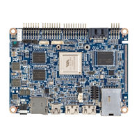
Pico-ITX Cortex-A9 Board
Brand: VIA Technologies
|
Category: Motherboard
|
Size: 7 MB
Table of Contents
Advertisement

VIA Technologies VAB-1000 User Manual (72 pages)
Pico-ITX Cortex-A9 Board
Brand: VIA Technologies
|
Category: Motherboard
|
Size: 2 MB
Table of Contents

VIA Technologies VAB-1000 Development Manual (43 pages)
Android BSP 3.0
Brand: VIA Technologies
|
Category: Desktop
|
Size: 1 MB
Table of Contents
Advertisement
VIA Technologies VAB-1000 Evaluation Manual (33 pages)
Android BSP 3.0
Brand: VIA Technologies
|
Category: Desktop
|
Size: 1 MB
Table of Contents
Advertisement
Related Products
- VIA Technologies VAB-800
- VIA Technologies VAB-820
- VIA Technologies VAB-630
- VIA Technologies VAB-950
- VIA Technologies VB8001-16 - VIA Motherboard - Mini ITX
- VIA Technologies VIA KT266A ChipsetMotherboard
- VIA Technologies VIA EPIA
- VIA Technologies VB9001
- VIA Technologies VX900
- VIA Technologies VIA P4PB 266E