Sign In
Upload
Manuals
Brands
VIA Technologies Manuals
Motherboard
VB9001
VIA Technologies VB9001 Manuals
Manuals and User Guides for VIA Technologies VB9001. We have
1
VIA Technologies VB9001 manual available for free PDF download: User Manual
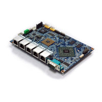
VIA Technologies VB9001 User Manual (44 pages)
High-integrated low-power platform ideal for network firewall and router applications
Brand:
VIA Technologies
| Category:
Motherboard
| Size: 3 MB
Table of Contents
Safety Precautions
3
Box Contents
4
Optional Accessories
4
Ordering Information
4
Table of Contents
5
1 Product Overview
9
Key Features
9
Product Specifications
10
Layout Diagram
12
Figure 1: Layout Diagram Of The Vb9001 (Back Panel I/O)
12
Figure 2: Layout Diagram Of The Vb9001 (Right Side)
12
Figure 3: Layout Diagram Of The Vb9001 Onboard (Top Side)
12
Figure 4: Layout Diagram Of The Vb9001 Onboard (Bottom Side)
12
Product Dimensions
13
Figure 5: Mounting Holes And Dimensions Of The Vb9001
13
Figure 6: External I/O Port Dimensions Of The Vb9001 (Back Panel)
13
Figure 7: External I/O Port Dimensions Of The Vb9001 (Right Side)
13
Height Distribution
14
Figure 8: Height Distribution Of The Vb9001 (Top Side)
14
Figure 9: Height Distribution Of The Vb9001 (Bottom Side)
14
2 External I/O Pin Descriptions and Functionality
15
COM Port
15
Gigabit Ethernet Port
15
Figure 10: COM Port Diagram
15
Figure 11: Gigabit Ethernet Port
15
Table 1: COM Port Pinouts
15
Table 2: Gigabit Ethernet Port Pinouts
15
DC-In Jack
16
Figure 12: DC-In Jack Diagram
16
Figure 13: DC-In Jack Specification Diagram
16
Table 3: Gigabit Ethernet Port Led Color Definitions
16
Table 4: DC-In Jack Pinouts
16
Table 5: DC-In Jack Specification Pinouts
16
3 Onboard I/O
17
USB 2.0 Pin Header
17
Front Panel Pin Header
17
Figure 14: USB 2.0 Pin Header Diagram
17
Figure 15: Front Panel Pin Header Diagram
17
Table 6: USB 2.0 Pin Header Pinouts
17
Table 7: Front Panel Pin Header Pinouts
17
SPI Connector
18
LPC Pin Header
18
Figure 16: SPI Connector Diagram
18
Figure 17: LPC Pin Header Diagram
18
Table 8: SPI Connector Pinouts
18
Table 9: LPC Pin Header Pinouts
18
GPIO Pin Header
19
VGA Pin Header
19
Figure 18: GPIO Pin Header Diagram
19
Figure 19: VGA Pin Header Diagram
19
Table 10: GPIO Pin Header Pinouts
19
Table 11: VGA Pin Header Pinouts
19
SATA Connector
20
SATA Power Connector
20
Figure 20: SATA Connector Diagram
20
Figure 21: SATA Power Connector Diagram
20
Table 12: SATA Connector Pinouts
20
Table 13: SATA Power Connector Pinouts
20
Fan Connector
21
3.10 Cmos Battery Connector
21
Figure 22: Fan Connector Diagram
21
Figure 23: Cmos Battery Connector Diagram
21
Table 14: Fan Connector Pinouts
21
Table 15: Cmos Battery Connector Pinouts
21
3.11 Cfast Slot
22
Figure 24: Cfast Slot Diagram
22
Table 16: Cfast Slot Pinouts
22
4 Onboard Jumpers
23
Figure 25: Jumper Settings Example
23
Clear CMOS Jumper
24
Figure 26: Clear CMOS Jumper Diagram
24
Table 17: Clear Cmos Jumper Settings
24
5 Hardware Installation
25
Suggested Minimum Chassis Dimensions
25
Figure 27: Suggested Minimum Chassis Dimensions
25
Figure 28: Suggested Minimum Chassis Height (Top Side)
26
Figure 29: Suggested Minimum Chassis Height (Bottom Side)
26
Suggested Minimum Chassis Height
26
Figure 31: Suggested Keepout Bottom Areas
27
Figure 30: Suggested Keepout Top Areas
27
Suggested Keepout Areas
27
6 BIOS Setup Utility
28
Entering the BIOS Setup Utility
28
Control Keys
28
Navigating the BIOS Menus
28
Getting Help
28
Main Menu
29
BIOS Information
29
Memory Information
29
System Language
29
System Date
29
System Time
29
Figure 32: Illustration Of The Main Menu Screen
29
Advanced Setting
30
Figure 33: Illustration Of The Advanced Settings Screen
30
S5 RTC Wake Settings
31
Figure 34: Illustration Of S5 Rtc Wake Settings Screen
31
Figure 35: Illustration Of Wake System With Fixed Time Screen When Enabled
31
Wake System with Fixed Time
31
6.6.1.1.1 Wake up Hour
32
6.6.1.1.2 Wake up Minute
32
6.6.1.1.3 Wake up Second
32
Figure 36: Illustration Of Wake System With Dynamic Time Screen When Enabled
32
Wake System with Dynamic Time
32
CPU Configuration
33
Figure 37: Illustration Of Cpu Configuration Screen
33
Figure 38: Illustration Of Ide Configuration Screen
34
IDE Configuration
34
Clock Generator Configuration
35
CPU Spread Spectrum
35
Figure 39: Illustration Of Clock Generator Configuration Screen
35
Pcie Spread Spectrum
35
Board Configuration
36
Figure 40: Illustration Of Board Configuration Screen
36
S5 Wake on LAN
36
Chipset Settings
37
Figure 41: Illustration Of Chipset Settings Screen
37
DRAM Configuration
38
DRAM Clock
38
Figure 42: Illustration Of Dram Configuration Screen
38
VGA Share Memory (Frame Buffer)
38
Watchdog Timer Control
39
Figure 43: Illustration Of Video Configuration Screen
39
Watchdog Timer Action
39
Watchdog Timer Count
39
Watchdog Timer Enable
39
Watchdog Timer Run/Stop
39
Boot Settings
40
Setup Prompt Timeout
40
Bootup Numlock State
40
Quiet Boot
40
Figure 44: Illustration Of Boot Settings Screen
40
7 Software and Technical Support
41
Microsoft Windows & QNX Support
41
VIA Smart ETK
41
Technical Supports and Assistance
41
Appendix.a. Installing Wireless Accessories
42
A.1. Installing Emio-5531 Usb Wi-Fi & Bluetooth Module
42
Figure 45: Installing EMIO-5531 to the Chassis
42
Figure 46: Connecting Usb Cable Wi-Fi Cable
42
Figure 47: Installing Wi-Fi Antenna Cable and Antenna
43
Figure 48: Connecting The Wi-Fi Antenna Cable To The Micro-Rf Connector
43
Advertisement
Advertisement
Related Products
VIA Technologies VB8001-16 - VIA Motherboard - Mini ITX
VIA Technologies VB6002 Series
VIA Technologies VB8004
VIA Technologies VB8002
VIA Technologies VB7007
VIA Technologies VB7008
VIA Technologies VB8001
VIA Technologies VB7009
VIA Technologies VB7002
VIA Technologies VB7001
VIA Technologies Categories
Motherboard
Computer Hardware
Desktop
Control Unit
Industrial PC
More VIA Technologies Manuals
Login
Sign In
OR
Sign in with Facebook
Sign in with Google
Upload manual
Upload from disk
Upload from URL