Sign In
Upload
Manuals
Brands
TransAct Manuals
Printer
ithaca 750
TransAct ithaca 750 Ticket Printer Manuals
Manuals and User Guides for TransAct ithaca 750 Ticket Printer. We have
1
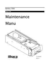
TransAct ithaca 750 Ticket Printer manual available for free PDF download: Maintenance Manual
TransAct ithaca 750 Maintenance Manual (58 pages)
Brand:
TransAct
| Category:
Printer
| Size: 0 MB
Table of Contents
Copyright
3
Important
3
Change History
5
Table of Contents
7
Chapter 1: General Information
11
What Is Covered in this Book
11
Service Information
11
Internet Support
12
Www.transact-Tech.com
12
Warranty Options
12
Contacting Transact's Ithaca Facility
13
Chapter 2: Series 700 Configuration System
14
Figure 1 Series 700 Core Unit and Configurable Options
14
Model 750 "Core" Printer: Main Chassis Assembly
15
750 "Core" Printer: Main Chassis Assembly Highlights
15
Figure 2 Model 750 "Core" Printer
15
Standard Features
16
750 Printing Highlights
16
Print Characteristics
16
Table 1 Font Statistics
16
Series 700 Printer Specifications
17
Dimensions
17
General
17
Interface
17
Printer
17
Checking Environmental Conditions of OEM Product
18
Printer Environmental Conditions
18
Relative Humidity
18
Ticket Environmental Conditions
18
Chapter 3: Configurable Options-Specifications
19
Ticket Supply Box Specifications
19
Power and Interface Communications
19
Ticket Low Sensor
19
Ticket Present Sensor Specifications
19
Bezel Assembly Exit Lamp Board Specifications
19
Power Requirements
19
Drawer Chassis Option
20
Power PCB and Interface Communications
20
Figure 3 Power Interface Location
20
Chapter 4: Operational Controls
21
Removing the Model 750 from the OEM Product
21
Using the Ticket Feed and Test Buttons for Diagnostics
21
Using Ticket Feed Button to Enter Diagnostics
21
Using Test and Ticket Feed Buttons to Enter Diagnostics
21
Figure 4 Release Knob Location
21
Loading Tickets into Feeding Mechanism
22
Ticket Stack Orientation and Loading
22
Figure 5 Ticket Loading and Feed Mechanism
22
Chapter 5: Electrical Connections
23
M750 Electrical Control System
23
Figure 6 Electrical Control System Operational Principles
23
Operator Interface
24
Cpu
24
Sensor Interface
24
Print Head Interface
24
A/D Converter
24
J1: 2-Pin: Connector Board (Lamp Board)
25
J3: 5-Pin: Connector Board (Ticket Low Sensor)
25
Table 2 Connector P1 - Molex 50-57-9402 J1
25
Table 3 Ticket Low Sensor, J3
25
J1: 14-Pin: Connector Board (Fllex Cable)
26
J2: 14-Pin: Connector Board (Discrete Wire)
26
Table 4 Connector Board Interface to Power Board Interface (Flex Cable), J1
26
Table 5 Power Board (Discrete Wire), J2, Molex 70555-0048
26
J4: 16-Pin: Connector Board (Interconnect Cable)
27
Table 6 Connector Board (Interconnect Cable), J4
27
J1: 20-Pin: Power Board (Input from OEM Host Machine)
28
Table 7 Power Board Interface to Host Interface, J1, Molex 15-41-7020
28
J3: 16-Pin: Power Board (Card Reader)
29
Table 8 Power Board Card Reader, J3
29
J2: 14-Pin: Power Board (Flex Cable)
30
Table 9 Power Board to Connector Board (Flex Cable), J2
30
J6: 3-Pin: Printer Controller Board (Black Dot Sensor)
31
J3: 15-Pin: Printer Controller Board (Print Head)
31
J5: 4-Pin: Printer Controller Board (Stepper Motor)
31
Table 10 Printer Controller Board (Black Dot Sensor), J6
31
Table 11 Printer Controller Board (Print Head), J3
31
Table 12 Printer Controller Board (Stepper Motor), J5
31
J7: 4-Pin: Printer Controller Board (Ticket Sensor)
32
J8: 14-Pin: Printer Controller Board (Interconnect Cable)
32
Table 13 Printer Controller Board (Ticket Sensor), J7
32
Table 14 Printer Controller Board (Interconnect Cable), J8
32
Serial Interface Specifications the XON/XOFF Protocol
33
Board Close-Ups and Physical Connections
33
Figure 7 Model 750 Wiring Schematic
33
Figure 8 Power Board Connections Schematic
33
Figure 9 Connector Board Connections Schematic
33
Figure 10 Controller Board Connections Schemaitc
33
Chapter 6: Adjustments and Troubleshooting
34
Making Adjustments
34
Necessary Tools
34
Black Dot Adjustment: Top of Form Preprinted Indicator
35
Determining if Black Dot (Top-Of-Form Mark) Needs Adjustment
35
Figure 11 Location of Top of Form Indicator on Back of Ticket
35
Adjusting the Black Dot Sensor
36
Figure 12 Black Dot Sensor Adjustment: Removing the Printer Chassis Assembly
36
Figure 13 Black Dot Sensor Adjustment: Potentiometer Location
37
Troubleshooting
38
Troubleshooting Checklist
38
Model 750 Troubleshooting Table: Determining the Problem
39
Table 15 Troubleshooting Reference Table
39
Chapter 7: Assembly/Disassembly
41
Precautions for Disassembly
41
Necessary Tools
41
Model 750 OEM Variations Notice
41
Removing the Assembly Components (from the Complete Assembly)
42
Figure 14 Removing the Assembly Components
42
Separating the Printer Chassis Assembly from the Main Chassis Assembly
43
Figure 15 Separating the Printer Chassis Assembly from the Main Chassis Assembly
43
Removing the Drawer Chassis Assembly Components
44
Figure 16 Removing the Drawer Chassis Assembly Components
44
Removing the Ticket Supply Box from the Main Chassis Assembly
45
Removing the Ticket Supply Box Components
45
Figure 17 Removing the Ticket Supply Box from the Main Chassis Assembly
45
Removing the Main Chassis Assembly Components
46
Figure 18 Removing the Main Chassis Assembly Components
46
Removing the Printer Chassis Assembly Components
47
Figure 19 Removing the Printer Chassis Assembly Components
47
Removing the Bezel Assembly from the Main Chassis Assembly
48
Figure 20 Removing the Bezel Assembly from the Main Chassis Assembly
48
Removing the Bezel Assembly Components
49
Figure 21 Removing the Bezel Assembly Components
49
Chapter 8: Parts Lists
50
Complete 750 Assembly
50
Figure 22 Complete 750 Assembly
50
Table 16 Complete 750 Assembly Parts List
50
Printer Chassis Assembly
51
Figure 23 Printer Chassis Assembly
51
Table 17 Printer Chassis Assembly
51
Drawer Chassis Assembly
52
Figure 24 Drawer Chassis Assembly
52
Table 18 Drawer Chassis Assembly
52
Bezel Assembly
53
Figure 25 Bezel/Chassis Assembly
53
Table 19 Bezel/Chassis Assembly Parts List
53
Main Chassis Assembly and Ticket Supply Box
54
Figure 26 Chassis/Bucket Assembly
54
Table 20 Chassis/Bucket Assembly Parts List
54
Main Chassis Assembly
55
Figure 27 Main Chassis Assembly
55
Table 21 Main Chassis Assembly Parts List
55
Bezel Assembly
56
Figure 28 Bezel Assembly Parts
56
Table 22 Bezel Assembly Parts List
56
Index
57
Advertisement
Advertisement
Related Products
TransAct ithaca 700 Series
TransAct Ithaca 93PLUS
TransAct Ithaca 90PLUS Series
TransAct Ithaca 8000
TransAct ITHACA 80PLUS
TransAct Ithaca 280
TransAct Ithaca 91PLUS
TransAct Ithaca 92PLUS
TransAct Ithaca 94PLUS
TransAct Ithaca BANKjet 1500
TransAct Categories
Printer
Touch terminals
Label Maker
Plotter
Desktop
More TransAct Manuals
Login
Sign In
OR
Sign in with Facebook
Sign in with Google
Upload manual
Upload from disk
Upload from URL