Sign In
Upload
Manuals
Brands
Trane Manuals
Controller
Tracer MP581
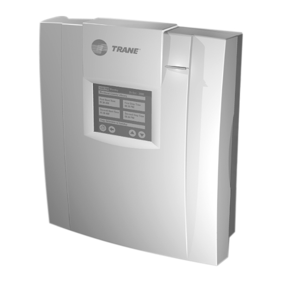
Trane Tracer MP581 Manuals
Manuals and User Guides for Trane Tracer MP581. We have
5
Trane Tracer MP581 manuals available for free PDF download: Programming Manual, Hardware Installation, Installation Instructions, Quick Reference Card
Trane Tracer MP581 Programming Manual (144 pages)
Programmable Controller
Brand:
Trane
| Category:
Controller
| Size: 2 MB
Table of Contents
Revision History
5
Table of Contents
7
Chapter 1 Overview
11
Tracer MP580/581 Plug-In
11
Using Rover Service Tool
11
Accessing the Tracer MP580/581
11
Using Online Help
12
Chapter 2 Viewing Status
13
Viewing the Status of Inputs
14
Viewing the Status of Binary and Analog Outputs
15
Overriding Binary and Analog Outputs
16
Releasing Binary and Analog Output Overrides
19
Viewing the Status of Binary and Analog Variables
19
Viewing Application Status
22
Viewing Comm5 Parameters
23
Viewing Custom Displays
24
Changing Binary and Analog Variables
25
Overriding the Occupancy Mode
26
Applying an Occupancy Override
26
Releasing an Occupancy Override
27
Chapter 3 Configuring the Tracer MP580/581
29
Configuring EX2 Expansion Modules
29
Configuring Inputs
31
Configuring Binary Inputs
31
Configuring Analog Inputs
34
Configuring Pulse Inputs
36
Configuring Outputs
38
Configuring Binary Outputs
38
Configuring Analog Outputs
39
Configuring Variables
41
Configuring Binary Variables
41
Configuring Analog Variables
43
Configuring User Security
45
Setting the Time and Date
47
Configuring Timers
48
Configuring the Operator Display
49
Configuring the Home Display
49
Configuring Custom Displays
51
Configuring an SCC or DAC Profile
54
Configuring the SCC Interface
54
Configuring the DAC Interface
55
Configuration Reports
57
Saving Configuration Reports
57
Printing Configuration Reports
57
Memory Reset
58
Unlocking Controller for Flash Download
58
Chapter 4 Using the Schedule Application
59
Viewing the Status of the Time-Of-Day Schedule
59
Setting up the Daily Schedule
60
Clearing a Start or Stop Time
62
Clearing the Event Times for a Day
62
Clearing All Daily Event Times
63
Copying a Daily Schedule
63
Setting up the Exception Schedule
64
Adding an Exception
64
Clearing an Exception
65
Editing an Exception
66
Setting up Occupancy Inputs
67
Synchronizing Time with Tracer Summit
69
Controlling the Occupancy Mode of the Tracer MP580/581
69
Manual Command
69
Time Schedule
70
Occupancy Sensor
70
Occupancy Binary Input
70
Bypass Timer
71
Chapter 5 Using the Calculations Application
75
Viewing the Status of a Calculation
75
Setting up a Calculation
76
Clearing a Calculation
79
Chapter 6 Graphical Programming Overview
81
Opening the TGP Editor
81
TGP Editor
82
Design Space
82
Output Display
82
Blocks
83
Menu Bar
83
Toolbars
83
Standard Toolbar
84
Alignment Toolbar
84
Block Toolbars
85
Program Toolbar
86
Showing or Hiding Toolbars
86
Short Cut Menus
87
Keyboard Short Cuts
87
Chapter 7 Creating a Graphical Program
89
Creating a New Program
89
Opening an Existing Program
89
Editing Program Properties
90
Setting Page Width and Size
92
Adding a Block
92
Editing Block Properties
93
Adding a Comment
94
Arranging Blocks
94
Moving Blocks
94
Aligning Blocks
95
Deleting a Block
95
Connecting Blocks Using Wired Connections
95
Connecting Blocks Using Wireless Connections
96
Refreshing the TGP Editor
101
Saving a Program
101
Printing a Program
101
Closing a Program
101
Chapter 8 Using the Occupancy and PID Blocks
103
Using the Occupancy Block
103
Using the Occupancy Block to Turn on a Supply Fan
104
Using the Occupancy Block to Adjust Setpoints
104
Using the PID Block
107
Setting up the PID Block Properties
107
Incorporating the PID Block
110
Chapter 9 Implementing a Graphical Program
113
Compiling a Program
113
Downloading a Program
113
Uploading a Program
114
Deleting a Program from the Tracer MP580/581
114
Viewing Program Status
114
Debugging a Program
115
Simulating a Program
116
Chapter 10 Network Variable Bindings
119
Overview
119
Network Variables
119
Binding Network Variables
119
Tracer MP580/581 Bindings
120
Receiving Data
120
Sending Data
125
Examples of Network Variable Bindings
128
Example 1: Display Sensor Readings from a Tracer MP503 on a Tracer MP581 Operator Display
128
Example 2: Display Sensor Readings from a Tracer MP503 on Two Different Tracer MP581 Operator Displays
130
Example 3: Control a Binary Output on the Tracer MP503 from a
132
Tracer MP581
132
Example 4: Use a Sensor Reading on a Tracer MP503 to Control a Pump VFD on a Tracer MP581
133
Index
137
Advertisement
Trane Tracer MP581 Hardware Installation (110 pages)
Brand:
Trane
| Category:
Controller
| Size: 3 MB
Table of Contents
Table of Contents
7
Chapter 1 Overview
11
Product Description
11
Specifications
11
Additional Components
12
Operator Display Models
12
Sensors
12
EX2 Expansion Modules
13
Power Transformer
13
Agency Listings/Compliance
14
Tracer MP581 Controller
14
Expansion Module
14
Inspection Upon Receipt
15
Tracer MP581 with Enclosure
15
Frame-Mounted Tracer MP581
15
Required Tools
15
Chapter 2 Installing the Frame-Mounted Tracer MP581
17
Enclosure Requirements
17
Installing the Termination Board
18
Chapter 3 Mounting the Enclosure
19
Selecting a Mounting Location
19
Operating Environment Requirements
19
Clearances
20
Mounting the Enclosure
22
Chapter 4 Wiring High-Voltage Ac Power
23
Local Power Requirements
23
Circuit Requirements
23
Wiring High-Voltage Power
24
Chapter 5 Wiring Inputs and Outputs
27
Input/Output Wiring Guidelines
27
Wire Routing
28
Providing Low-Voltage Power for Inputs and Outputs
29
Screw-Terminal Locations
30
Wiring Universal Inputs
31
Wiring Binary Inputs
31
Wiring 0-10 VDC Analog Inputs
32
Wiring 0-20 Ma Analog Inputs
33
Wiring Variable Resistance Analog Inputs
34
Wiring Analog Outputs
35
Wiring Binary Outputs
36
Checking Inputs
37
Checking Thermistor Inputs
37
Checking Resistance Temperature Detector (RTD) Inputs
39
Checking Linear Resistance Inputs
40
Checking Linear Voltage 0-10 VDC Inputs
40
Checking Linear Current 0-20 Ma Inputs
41
Checking Binary Inputs
41
Checking Outputs
42
Checking Binary Outputs
42
Checking 0-10 VDC Analog Outputs
43
Checking 0-20 Ma Analog Outputs
44
Chapter 6 Installing the Pressure Sensor
45
Mounting the Pressure Sensor
45
Checking the Pressure Sensor
47
Chapter 7 Wiring Comm5 Links
49
Wiring and Topology Recommendations
49
Recommended Wiring Practices
50
Wiring Requirements
51
Twisted-Pair Wire
51
Recommended Wiring Configuration
51
Termination Resistance Placement for Comm5 Links
52
Comm5 Physical Link Repeater
54
When Is the Link Repeater Required
54
Link Repeater Guidelines
54
Link Repeater Connections
54
Comm5 Zone Sensor Comm Jack
56
Zone Sensor Communication Stubs
56
Verifying Communication Status
57
Comm LED
57
Wiring Comm5 to the Tracer MP581
58
EMI/RFI Considerations
60
Checking the Earth Ground
60
Sectioning the Shield on the Comm5 Link
61
Chapter 8 Installing the Circuit Board
63
Chapter 9 Installing the Door
67
Installing the Door
67
Removing the Door
68
Chapter 10 Installing the Stand-Alone Operator Display
69
Chapter 11 Connecting the Portable Operator Display
73
Using the Carrying Case
73
Connecting the Operator Display
73
Chapter 12 Setting up the Operator Display
75
Calibrating the Operator Display
75
Setting up Time and Date
76
Adjusting Brightness and Contrast
76
Chapter 13 Installing EX2 Expansion Modules
77
Operating Environment
77
Storage Environment
79
Mounting Location
79
Attaching the Terminal Strips
79
Mounting the Frame-Mount Module
80
Mounting the Metal-Enclosure Module
81
AC-Power Wiring
82
Wiring AC-Power to the Frame-Mount Module
83
Wiring AC-Power to the Metal-Enclosure Module
83
I/O Bus Wiring
84
Setting the I/O Bus Addresses
85
Input/Output Terminal Wiring
86
Universal Inputs
87
Binary Outputs
87
Analog Outputs
87
Analog Output and Universal Input Setup
87
Interpreting EX2 Leds
89
Binary Output Leds
89
Status LED
90
Communications Leds
90
Chapter 14 Verifying Operation and Communication
91
Service Pin Button
91
Interpreting Leds
92
Binary Output Leds
92
Service LED
92
Status LED
93
Comm LED
93
Leds on the EX2 Expansion Module
93
Chapter 15 Troubleshooting
95
Initial Troubleshooting
96
Binary Output Troubleshooting
97
Analog Output Troubleshooting
98
Universal Input Troubleshooting
99
Chapter 16 Other Literature
103
Index
105
Trane Tracer MP581 Installation Instructions (2 pages)
Main Circuit Board
Brand:
Trane
| Category:
Controller
| Size: 1 MB
Table of Contents
Warnings, Cautions, and Notices
1
Important Environmental Concerns
1
Important Responsible Refrigerant Practices
1
Operating Environment
1
Removing Existing Circuit Board
2
Installing New Circuit Board
2
Agency Listings and Compliance
2
Advertisement
Trane Tracer MP581 Installation Instructions (2 pages)
Frame-mounted
Brand:
Trane
| Category:
Controller
| Size: 2 MB
Trane Tracer MP581 Quick Reference Card (2 pages)
Operator Display
Brand:
Trane
| Category:
Monitor
| Size: 0 MB
Advertisement
Related Products
Trane Tracer MP580
Trane mP30
Trane Mini
Trane Multi-Split
Trane Tracer MP501
Trane TRACER CH532
Trane Tracer ZN.520
Trane Tracer ZN524
Trane Tracer ZN521
Trane Tracer VV550
Trane Categories
Air Conditioner
Heat Pump
Chiller
Air Handlers
Furnace
More Trane Manuals
Login
Sign In
OR
Sign in with Facebook
Sign in with Google
Upload manual
Upload from disk
Upload from URL