Sign In
Upload
Manuals
Brands
Toshiba Manuals
UPS
G2020 Series
Toshiba G2020 Series Manuals
Manuals and User Guides for Toshiba G2020 Series. We have
3
Toshiba G2020 Series manuals available for free PDF download: Installation And Operation Manual, Installation Manual
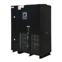
Toshiba G2020 Series Installation And Operation Manual (86 pages)
480/480 V 500kVA/750kVA
Brand:
Toshiba
| Category:
UPS
| Size: 5.21 MB
Table of Contents
Table of Contents
5
List of Tables
6
1 How to Use this Manual
9
Notice Icons
9
Qualified Personnel
10
2 Introduction
11
Safety Precautions
12
Table 2-1 UPS Installation Environment
13
Table 2-2 Rating of Bypass Input Circuit Breaker
14
3 General
15
Definitions
16
Operation Overview
16
Normal Operation: Load Power Supplied by each System UPS Inverter
17
Figure 3-1 Single Line Diagram - Normal Operation: Load Fed by UPS Inverter
17
Bypass Operation: Load Power Supplied through UPS Internal Static Bypass Line
18
Figure 3-2 Single Line Diagram - Bypass Operation: Load Fed through Static Bypass Line
18
Battery Operation: Load Power Supplied by UPS Battery
19
Figure 3-3 Single Line Diagram - Battery Operation: Load Fed by Battery
19
Battery Charging Operation
20
Figure 3-4 Typical Battery Charging Curve
20
UPS Parts Location
21
Figure 3-5 UPS Parts Location (500Kva)
21
Figure 3-6 UPS Parts Location (750Kva)
22
Figure 3-7 Display PCB DPAU-81
23
Figure 3-8 MAIN PCB UPHR-X
23
Figure 3-9 External I/F PCB IOAU-09
23
Figure 3-10 Parallel I/F PCB IFAU-09
24
Specifications
25
Table 3-1 Power Specifications
25
Table 3-2 UPS Module Information
25
Table 3-3 UPS Module Information (Packing Dimension)
25
Table 3-4 UPS Module Efficiency
25
Table 3-5 Specifications
26
Table 3-6 Rating of Contactors, Breakers, and Fuses
27
4 Operator Controls and Indicators
28
Figure 4-1 Operation/Display Panel (Front Panel)
28
Led Display
29
EPO BUTTON (Emergency Power off Button)
29
Liquid Crystal Display
29
Menu
30
Figure 4-2 Main Screen
30
Figure 4-3 Startup/Shutdown Screen
30
Figure 4-4 Startup Guidance
31
Figure 4-5 Shutdown Guidance
31
Figure 4-6 Input Values
31
Figure 4-7 Output Values
31
Figure 4-8 Values in Battery Operation
31
Figure 4-9 Remote/Local Operation Select
32
Figure 4-10 Date & Time Adjustment
32
Figure 4-11 Log Menu
33
Figure 4-12 Event Log
33
Figure 4-13 Battery Log
33
Input Power Failure
34
Fault Indication
34
Figure 4-14 Main Screen (Battery Operation)
34
Figure 4-15 Measurement Screen (Battery Operation)
34
Figure 4-16 Main Screen (Fault Indication)
34
External Aux Contact Input and Output Terminal Blocks
35
Figure 4-17 Message Screen
35
Figure 4-18 Location of External Signal Terminal Block on IOAU-09 PCB
35
Aux Contacts - Input
36
Figure 4-19 Control Wiring for Aux Input Contacts
36
Figure 4-20 External Signal Input Terminal Block (with Default Settings)
37
Table 4-1 External Input Functions
38
Aux Contacts - Output
39
Figure 4-21 Control Wiring for Aux Output Contacts
39
Figure 4-22 External Signal Output Terminal Block (with Default Settings)
39
Table 4-2 External Output Functions
40
Remoteye INTRODUCTION
41
Figure 4-23 Remoteye® Installation (Overview 500Kva)
41
Figure 4-24 Connection between Display Control PCB (SW1) and Remoteye
42
Module
42
Table 4-3 Parts List for UPS Monitoring
43
Figure 4-25 PSAU-60 (PS1)
43
Figure 4-26 DPAU-81 (SW1)
43
Figure 4-27 Cable1 (3BBA0083P001)
43
Connector Definition
44
Figure 4-28 Connector (CN1) of PSAU-60 (PS1)
44
Figure 4-29 Terminal Block (TN) and VH Connector (CN2) of PSAU-60 (PS1)
44
Figure 4-30 Connector (CN44) of PSAU-60 (PS1)
44
Figure 4-31 Connector (CN27) of DPAU-81 (SW1)
45
5 Installation and Operation
46
Transportation and Installation
46
Installation Procedure
46
Table 5-1 Transport by Overhead Crane
46
Table 5-2 List of UPS Weights
46
Procedure for Cable Connections
47
Table 5-3 Maximum Permitted Fault Current
47
Table 5-4 Recommended Cable Sizes
50
Table 5-5 Recommended Hardware
50
Table 5-6 Crimp Type Compression Lug
51
Figure 5-1 UPS Terminal Designation
51
Figure 5-2 Diagram of Input/Output Bus Bars and Terminal Blocks (500Kva)
52
Figure 5-3 Diagram of Input/Output Bus Bars and Terminal Blocks (750Kva)
53
Figure 5-4 Diagram of Power Wire & Control Wire Inter-Connect between UPS and Battery
54
Figure 5-5 Diagram of Power Wire Connections (Parallel System Configuration)
55
Figure 5-6 Diagram of Power & Control Wire Connections for 2 Units in MMS Configuration
56
Figure 5-7 Detail of IFAU-09 Control Wire Connections for 2 Units in MMS Configuration
57
Figure 5-8 Diagram of Power & Control Wire Connections for 3-4 Units in MMS Configuration
58
Figure 5-9 Detail of IFAU-09 Control Wire Connections for 3 or 4 Units in MMS Configuration
59
Figure 5-10 Diagram of Power Wire & Control Wire Connections for 5 to 8 Units in MMS Configuration
60
Figure 5-11 Detail of IFAU-09 Control Wire Connections for 5 to 8 Units in MMS Configuration
61
Operating Procedures
62
Figure 5-12 Circuit Protectors Location
62
Figure 5-13 Automatic Startup of Inverter and Converter
63
Figure 5-14 Close Battery Breaker
63
Figure 5-15 Press and Hold START Button
63
Figure 5-16 Transfer from Online to Bypass
64
Figure 5-17 Transfer from Bypass to Online
64
Figure 5-18 Initiate Shutdown
65
Figure 5-19 UPS Transfers to Bypass
65
Figure 5-20 Open Battery Breaker
66
Figure 5-21 LCD Screen (MMS Operation)
67
6 Response to Ups Failure
68
7 Parts Replacement
69
Table 7-1 Standard Replacement Parts List
69
8 Fault Codes
70
Table 7-2 Replacement Air Filters
70
Table 8-1 Fault Codes
70
9 Daily Inspection
75
Table 9-1 How to Perform Daily Inspection
75
APPENDIX A Installation Planning Guides (IPG) & Outline Drawings
76
APPENDIX B Index
82
Advertisement
Toshiba G2020 Series Installation Manual (28 pages)
MMS KIT
Brand:
Toshiba
| Category:
UPS
| Size: 1.42 MB
Table of Contents
Table of Contents
5
1 How to Use this Manual
7
1.1 Notice Icons
7
1.2 Qualified Personnel
8
2 Overview
9
Figure 2-1 Parallel-Connection between Upss
9
3 MMS KIT Parts List
10
Table 3-1 Parts List of MMS KIT
10
Figure 3-1 MMS KIT Parts Identification
11
4 MMS Parts Location
12
Figure 4-1 MMS Parts Location (Rear Side of Door)
12
Figure 4-2 MMS Parts Location (Inside of Landing Cabinet)
13
Figure 4-3 Diagram of MMS Kit Installation
14
5 Installation Procedure
15
Parallel Control Board (TLCR-E*)
15
Figure 5-1 Location of Ground Bus Bar (Upper)
15
Figure 5-2 Location of Parallel Control Board (TLCR-E*)
15
Figure 5-3 Parallel Control Board (TLCR-E*) Installation Procedure
16
Parallel Interface Board (IFAU-09*)
17
Figure 5-4 Location of Parallel Interface Board (IFAU-09*)
17
Figure 5-5 Parallel Interface Board (IFAU-09*) Installation Procedure
17
Figure 5-6 Parallel Interface Board (IFAU-09*) Installation Procedure (Continued)
18
Figure 5-7 Parallel Interface Board (IFAU-09*) Installation Procedure (Continued)
19
6 Dip Switch Setting on Parallel Interface Board (IFAU-09*)
20
Table 6-1 Dip Switch Setting
20
Figure 6-1 Dip Switch Location on Parallel Interface Board (IFAU-09*)
20
APPENDIX A Parallel Operation System Connection
21
Figure A-1 Diagram of Power Wire Connections (Parallel System Configuration)
21
Figure A-2 Diagram of Power Wire and Control Wire Connection (for 2 - 4 Units in MMS)
22
Figure A-3 Diagram of Communication Cable Connection (for 2 - 4 Units in MMS)
23
Figure A-4 Diagram of Power Wire and Control Wire Connection (for 5 - 8 Units in MMS)
24
Figure A-5 Diagram of Communication Cable Connection (for 5 - 8 Units in MMS)
25
Toshiba G2020 Series Installation Manual (22 pages)
SYNC KIT 480/480 V 500/750 kVA
Brand:
Toshiba
| Category:
UPS
| Size: 1.32 MB
Table of Contents
Table of Contents
5
1 How to Use this Manual
7
1.1 Notice Icons
7
1.2 Qualified Personnel
8
2 Overview
9
Figure 2-1: Synchronous Operation Configuration
9
3 Toshiba Sync KIT Parts List
10
Table 3-1: Parts List of TOSHIBA SYNC KIT
10
Figure 3-1: TOSHIBA SYNC KIT Parts Identification
11
4 Toshiba Sync KIT Parts Location
12
Figure 4-1: Toshiba Sync KIT Parts Location (MASTER UPS)
12
Figure 4-2: Toshiba Sync KIT Parts Location (SLAVE UPS)
13
5 MASTER UPS Installation Procedure
14
Figure 5-1: Installation Procedure for MASTER UPS
14
6 SLAVE UPS Installation Procedure
15
Figure 6-1: Installation Procedure for SLAVE UPS (1)
16
Figure 6-2: Installation Procedure for SLAVE UPS (2)
16
Figure 6-3: Installation Procedure for SLAVE UPS (3)
17
Figure 6-4: Installation Procedure for SLAVE UPS (4)
17
7 SLAVE UPS Setting Procedure
18
Figure 7-1: SLAVE UPS Setting Procedure
19
8 Verify Proper Setup
20
Figure 8-1: Example of TOSHIBA SYNC Operation Display
20
Advertisement
Advertisement
Related Products
Toshiba G8000U Series
Toshiba G9M-014-10125HW23F
Toshiba G9M-014-10150HW23F
Toshiba G9M-014-10250HW23F
Toshiba G9M-014-10350HW23F
Toshiba G9M-014-10125HW63F
Toshiba G9M-014-10500HW23F
Toshiba G9M-014-10150HW63F
Toshiba G9M-014-10350HW63F
Toshiba G9M-014-10500HW63F
Toshiba Categories
Laptop
Air Conditioner
TV
LCD TV
All in One Printer
More Toshiba Manuals
Login
Sign In
OR
Sign in with Facebook
Sign in with Google
Upload manual
Upload from disk
Upload from URL